EP0348983A2 - Procédé de charge et de décharge d'une batterie et source d'énergie adoptant ce procédé - Google Patents
Procédé de charge et de décharge d'une batterie et source d'énergie adoptant ce procédé Download PDFInfo
- Publication number
- EP0348983A2 EP0348983A2 EP89111880A EP89111880A EP0348983A2 EP 0348983 A2 EP0348983 A2 EP 0348983A2 EP 89111880 A EP89111880 A EP 89111880A EP 89111880 A EP89111880 A EP 89111880A EP 0348983 A2 EP0348983 A2 EP 0348983A2
- Authority
- EP
- European Patent Office
- Prior art keywords
- battery
- battery blocks
- blocks
- boosting coil
- diode
- Prior art date
- Legal status (The legal status is an assumption and is not a legal conclusion. Google has not performed a legal analysis and makes no representation as to the accuracy of the status listed.)
- Granted
Links
Images




Classifications
-
- H—ELECTRICITY
- H01—ELECTRIC ELEMENTS
- H01M—PROCESSES OR MEANS, e.g. BATTERIES, FOR THE DIRECT CONVERSION OF CHEMICAL ENERGY INTO ELECTRICAL ENERGY
- H01M10/00—Secondary cells; Manufacture thereof
- H01M10/42—Methods or arrangements for servicing or maintenance of secondary cells or secondary half-cells
- H01M10/44—Methods for charging or discharging
- H01M10/441—Methods for charging or discharging for several batteries or cells simultaneously or sequentially
-
- B—PERFORMING OPERATIONS; TRANSPORTING
- B60—VEHICLES IN GENERAL
- B60L—PROPULSION OF ELECTRICALLY-PROPELLED VEHICLES; SUPPLYING ELECTRIC POWER FOR AUXILIARY EQUIPMENT OF ELECTRICALLY-PROPELLED VEHICLES; ELECTRODYNAMIC BRAKE SYSTEMS FOR VEHICLES IN GENERAL; MAGNETIC SUSPENSION OR LEVITATION FOR VEHICLES; MONITORING OPERATING VARIABLES OF ELECTRICALLY-PROPELLED VEHICLES; ELECTRIC SAFETY DEVICES FOR ELECTRICALLY-PROPELLED VEHICLES
- B60L53/00—Methods of charging batteries, specially adapted for electric vehicles; Charging stations or on-board charging equipment therefor; Exchange of energy storage elements in electric vehicles
- B60L53/10—Methods of charging batteries, specially adapted for electric vehicles; Charging stations or on-board charging equipment therefor; Exchange of energy storage elements in electric vehicles characterised by the energy transfer between the charging station and the vehicle
- B60L53/14—Conductive energy transfer
-
- B—PERFORMING OPERATIONS; TRANSPORTING
- B60—VEHICLES IN GENERAL
- B60L—PROPULSION OF ELECTRICALLY-PROPELLED VEHICLES; SUPPLYING ELECTRIC POWER FOR AUXILIARY EQUIPMENT OF ELECTRICALLY-PROPELLED VEHICLES; ELECTRODYNAMIC BRAKE SYSTEMS FOR VEHICLES IN GENERAL; MAGNETIC SUSPENSION OR LEVITATION FOR VEHICLES; MONITORING OPERATING VARIABLES OF ELECTRICALLY-PROPELLED VEHICLES; ELECTRIC SAFETY DEVICES FOR ELECTRICALLY-PROPELLED VEHICLES
- B60L58/00—Methods or circuit arrangements for monitoring or controlling batteries or fuel cells, specially adapted for electric vehicles
- B60L58/10—Methods or circuit arrangements for monitoring or controlling batteries or fuel cells, specially adapted for electric vehicles for monitoring or controlling batteries
- B60L58/18—Methods or circuit arrangements for monitoring or controlling batteries or fuel cells, specially adapted for electric vehicles for monitoring or controlling batteries of two or more battery modules
- B60L58/22—Balancing the charge of battery modules
-
- H—ELECTRICITY
- H02—GENERATION; CONVERSION OR DISTRIBUTION OF ELECTRIC POWER
- H02J—ELECTRIC POWER NETWORKS; CIRCUIT ARRANGEMENTS OR SYSTEMS FOR SUPPLYING OR DISTRIBUTING ELECTRIC POWER; SYSTEMS FOR STORING ELECTRIC ENERGY
- H02J7/00—Circuit arrangements for charging or discharging batteries or for supplying loads from batteries
- H02J7/50—Circuit arrangements for charging or discharging batteries or for supplying loads from batteries acting upon multiple batteries simultaneously or sequentially
- H02J7/52—Circuit arrangements for charging or discharging batteries or for supplying loads from batteries acting upon multiple batteries simultaneously or sequentially for charge balancing, e.g. equalisation of charge between batteries
- H02J7/56—Active balancing, e.g. using capacitor-based, inductor-based or DC-DC converters
-
- Y—GENERAL TAGGING OF NEW TECHNOLOGICAL DEVELOPMENTS; GENERAL TAGGING OF CROSS-SECTIONAL TECHNOLOGIES SPANNING OVER SEVERAL SECTIONS OF THE IPC; TECHNICAL SUBJECTS COVERED BY FORMER USPC CROSS-REFERENCE ART COLLECTIONS [XRACs] AND DIGESTS
- Y02—TECHNOLOGIES OR APPLICATIONS FOR MITIGATION OR ADAPTATION AGAINST CLIMATE CHANGE
- Y02E—REDUCTION OF GREENHOUSE GAS [GHG] EMISSIONS, RELATED TO ENERGY GENERATION, TRANSMISSION OR DISTRIBUTION
- Y02E60/00—Enabling technologies; Technologies with a potential or indirect contribution to GHG emissions mitigation
- Y02E60/10—Energy storage using batteries
-
- Y—GENERAL TAGGING OF NEW TECHNOLOGICAL DEVELOPMENTS; GENERAL TAGGING OF CROSS-SECTIONAL TECHNOLOGIES SPANNING OVER SEVERAL SECTIONS OF THE IPC; TECHNICAL SUBJECTS COVERED BY FORMER USPC CROSS-REFERENCE ART COLLECTIONS [XRACs] AND DIGESTS
- Y02—TECHNOLOGIES OR APPLICATIONS FOR MITIGATION OR ADAPTATION AGAINST CLIMATE CHANGE
- Y02T—CLIMATE CHANGE MITIGATION TECHNOLOGIES RELATED TO TRANSPORTATION
- Y02T10/00—Road transport of goods or passengers
- Y02T10/60—Other road transportation technologies with climate change mitigation effect
- Y02T10/70—Energy storage systems for electromobility, e.g. batteries
-
- Y—GENERAL TAGGING OF NEW TECHNOLOGICAL DEVELOPMENTS; GENERAL TAGGING OF CROSS-SECTIONAL TECHNOLOGIES SPANNING OVER SEVERAL SECTIONS OF THE IPC; TECHNICAL SUBJECTS COVERED BY FORMER USPC CROSS-REFERENCE ART COLLECTIONS [XRACs] AND DIGESTS
- Y02—TECHNOLOGIES OR APPLICATIONS FOR MITIGATION OR ADAPTATION AGAINST CLIMATE CHANGE
- Y02T—CLIMATE CHANGE MITIGATION TECHNOLOGIES RELATED TO TRANSPORTATION
- Y02T10/00—Road transport of goods or passengers
- Y02T10/60—Other road transportation technologies with climate change mitigation effect
- Y02T10/7072—Electromobility specific charging systems or methods for batteries, ultracapacitors, supercapacitors or double-layer capacitors
-
- Y—GENERAL TAGGING OF NEW TECHNOLOGICAL DEVELOPMENTS; GENERAL TAGGING OF CROSS-SECTIONAL TECHNOLOGIES SPANNING OVER SEVERAL SECTIONS OF THE IPC; TECHNICAL SUBJECTS COVERED BY FORMER USPC CROSS-REFERENCE ART COLLECTIONS [XRACs] AND DIGESTS
- Y02—TECHNOLOGIES OR APPLICATIONS FOR MITIGATION OR ADAPTATION AGAINST CLIMATE CHANGE
- Y02T—CLIMATE CHANGE MITIGATION TECHNOLOGIES RELATED TO TRANSPORTATION
- Y02T90/00—Enabling technologies or technologies with a potential or indirect contribution to GHG emissions mitigation
- Y02T90/10—Technologies relating to charging of electric vehicles
- Y02T90/14—Plug-in electric vehicles
-
- Y—GENERAL TAGGING OF NEW TECHNOLOGICAL DEVELOPMENTS; GENERAL TAGGING OF CROSS-SECTIONAL TECHNOLOGIES SPANNING OVER SEVERAL SECTIONS OF THE IPC; TECHNICAL SUBJECTS COVERED BY FORMER USPC CROSS-REFERENCE ART COLLECTIONS [XRACs] AND DIGESTS
- Y10—TECHNICAL SUBJECTS COVERED BY FORMER USPC
- Y10S—TECHNICAL SUBJECTS COVERED BY FORMER USPC CROSS-REFERENCE ART COLLECTIONS [XRACs] AND DIGESTS
- Y10S320/00—Electricity: battery or capacitor charging or discharging
- Y10S320/34—Robot, hybrid, recreational or emergency vehicle
Definitions
- the present invention relates to a method of charging and discharging a battery having a plurality of electrochemical cells which dissolve an active material from the electrodes into the electrolyte during the discharging process and deposit the active material on the surfaces of the electrodes during the charging process and an apparatus adopting this method. More particularly, the present invention relates to such a method and apparatus for achieving full discharge in order to equalize the electrodes.
- a metal-halogen battery such as a zinc-bromine battery having a plurality of electrochemical cells which dissolve an active material from the electrodes into the electrolyte during the discharging process and deposit the active material on the surfaces of the electrodes in the charging process.
- a battery of this system is disclosed in, for example, Japanese Patent Laid-Open No. 132775/1981. The prior art will be explained in the following with reference to Fig. 12.
- the reference numeral 112 represents a container of a electrochemical cell which is a structural unit of a battery.
- the container 112 accommodates a negative electrode 114, a positive electrode 116 and a separator film 118 for separating the negative electrode 114 and the positive electrode 116 from each other.
- an electrolyte on the negative electrode side is supplied from an electrolyte tank 122 through a pipe 120 and a pump 124, and to the positive electrode 116, an electrolyte on the positive electrode side is supplied from an electrolyte tank 130 through a pipe 128 and a pump 126.
- the electrolyte tank 130 on the positive electrode side may accommodate a complex tank (not shown) which stores bromine in the form of a complex.
- the positive electrode 116 and the negative electrode 114 are composed of a conductive resin material such as carbon plastic for the purpose of lightening the weight.
- the Zn2+ ions in the electrolyte are deposited on the negative electrode 114 as Zn, and Br ⁇ ions are changed into Br2 on the side of the positive electrode 116 and dispersed in the electrolyte in the form of a complex.
- Zn deposited on the negative electrode 114 dissolves in the electrolyte in the form of Zn2+ ions, and Br2 dissolves in the electrolyte in the form of Br ⁇ ions.
- a battery practically used is composed of a multiplicity of such cells laminated in series in order to obtain a desired output voltage.
- the difference in the amount of Zn deposit namely, the difference in the amount of charge increases with the lapse of time whether it is in operation or out of operation, as indicated by the solid line in Fig. 7.
- the total capacity and the voltage of the battery are reduced.
- the battery before charge has been fully discharged so as to dissolve the total amount of Zn deposited on the negative electrodes in the electrolyte.
- the battery is divided into a plurality of battery blocks and the discharge current is increased for achieving full discharge in any given block in comparison with the other blocks in order to achieve the full discharge of the battery in operation.
- Japanese Patent Laid-Open No. 49577/1985 discloses a method of achieving the full discharge of a give one battery block in the same structure by feeding from the battery block to an auxiliary battery.
- the present invention provides a method of charging and discharging a battery having a plurality of electrochemical cells which dissolve an active material such as zinc ions from the electrodes into the electrolyte in the discharging process and deposit the active material on the surfaces of the negative electrodes in the charging process, the method comprising: preparing a battery composed of a plurality of battery blocks each of which is composed of a plurality of the electrochemical cells connected in series to each other; providing a step of fully discharging any given battery block among the plurality of battery blocks by transferring the charges of the given battery block to at least one of the other battery blocks through a booster means; and repeating the step so that all the plurality of battery blocks subsequently experience at least one cycle of full discharge within a predetermined period of time.
- the present invention also provides a power source apparatus comprising: electrochemical cells for dissolving an active material from the electrodes into the electrolyte in the discharging process and depositing the active material on the surfaces of the electrodes in the charging process; battery blocks each of which is composed of a plurality of the electrochemical cells connected in series to each other; a battery composed of a plurality of the battery blocks connected to each other; a booster means which is connected to any given battery block among the plurality of battery blocks for raising the output voltage of the given battery block; a charge transfer passage for connecting the output side of the booster means to at least one of the other battery blocks; and a control circuit for controlling the boosting operation of the booster means and the charges transferred through the charge transfer passage; whereby each of the battery blocks experiences at least one cycle of full discharge within a predetermined period of time.
- the electric power remaining in the battery block which is to be fully discharged is transferred to another battery block through the booster means, so that full discharge for equalization is carried out without causing a loss of electric power.
- This method can be carried out while the battery is in operation, namely, while the battery supplies electric power to the load.
- This method can also be carried out while the whole battery is out of operation, because there is no loss of electric power.
- Figs. 1 and 2 show a first embodiment of an apparatus which adopts a method of charging and discharging a battery according to the present invention.
- Fig. 1 shows the structure of the apparatus in a state of charging the battery in order to store energy therein
- Fig. 2 shows the structure of the apparatus in a state of discharging the battery in order to drive the load.
- a charger 12 which is fed from a commercial power source 10 is connected to contactors 14 and 16.
- the contactors 14 and 16 have contacts A, B and C, D, respectively, which are switched from each other and connected to contacts X and Y, respectively.
- Battery blocks 18 and 20 are connected to the contactors 14 and 16, respectively. That is, the positive terminal of the battery block 18 is connected to the contact A of the contactor 14, the negative terminal of the battery block 18 and the positive terminal of the battery block 20 are connected to the contacts B and C, and the negative terminal of the battery block 20 is connected to the contact D.
- the AC power (generally 100 V or 200 V) supplied from the commercial power source 10 is converted into a predetermined DC power by the charger 12. If the contact X of the contactor 14 is connected to the contact A and the contact Y of the contactor 16 is connected to the contact D, a predetermined DC power is supplied to the battery blocks 18 and 20 which are connected in series to each other, thereby charging the battery blocks 18 and 20.
- a power converter 22 is connected to the contactors 14 and 16, and to the power converter 22 a load 24 such as a motor is connected, as shown in Fig. 2.
- the power of the battery block 18 is supplied to the load 24 through the power converter 22, while the power of the battery block 20 is supplied to the load 24 through the power converter 22 when the contact X of the contactor 14 is connected to the contact B and the contact Y of the contactor 16 is connected to the contact D.
- the power converter 22 is composed of a chopper, an inverter and the like, and supplies the DC power from the battery block 18 or 20 to the load 24 such as an induction motor in the form of a predetermined AC power.
- the apparatus is further provided with a booster circuit 25 as a booster means. That is, transistors 26 and 28 and diodes 30 and 32 are connected to the battery blocks 18 and 20.
- the collector of the transistor 26 is connected to the positive electrode side of the battery block 18, the emitter of the transistor 28 is connected to the negative electrode side of the battery block 20, and the connecting portion of the collector and the emitter of the transistors 26 and 28 is connected to the connecting portion of the battery blocks 18 and 20.
- the diodes 30 and 32 are disposed in such a manner as to prevent a short-circuit current from flowing from the positive electrode of the battery block 18 to the negative electrode of the battery block 20.
- the connecting point of the transistors 26 and 28 and the connecting point 34 of the diodes 30 and 32 are connected to the connecting portion of the battery blocks 18 and 20 through a boosting coil 36.
- the transistors 26 and 28 are turned on and off in accordance with a signal supplied from a control circuit 40 through a switch 38.
- the control circuit 40 includes a rectangular wave oscillator such as a multivibrator which is capable of adjusting a pulse width and pulse frequency and controls the on/off operation of the transistors 26 and 28.
- the battery blocks 18 and 20 are connected in series and a power which is adjusted to predetermined current and voltage is supplied thereto from the charger 12 so as to charge the battery as a whole.
- the contacts of the contactors 14 and 16 are switched so as to charge the other battery block solely. It is necessary to lower the voltage supplied to half the initial voltage simultaneously with the switching operation.
- the power is subsequently supplied from the battery blocks 18 and 20 to the load 24 through the power converter 22.
- full discharge for equalization of either of the battery blocks 18 and 20 is enabled by the following operation whether the battery blocks 18 or 20 is supplying a power to the load 24 or they are not operated.
- a rectangular wave signal is supplied from the control circuit 40 to either of the transistors 26 and 28 through the switch 38.
- the signals is supplied to the base of either of the transistors 26 and 28 so as to turn on and off the transistor.
- the power stored in the boosting circuit 36 raises the potential of the connecting point 34 of the diodes 30 and 32, and flows to the positive electrode side of the battery block 18 through the diode 30, thereby charging the battery block 18.
- Fig. 3 shows the state of the rectangular wave which is output from the control circuit 40, and the changes in the current values of the transistor 28, the diode 30 and the boosting coil 36 in accordance with the rectangular wave. It is understood from Fig. 3, that the current value of the transistor 28 gradually rises and when the current value becomes zero, a charge current flows to the battery block 18 through the diode 30.
- two battery blocks are provided and they are discharged alternately, but the number of battery blocks is not limited to two, and a combination of three battery blocks or more may be usable.
- N battery blocks are provided.
- a power is transferred from the n-th battery block to the n-1)-th battery block to fully discharge the n-th battery block. Repetitions of such full discharge on a predetermined cycle subsequently enables the full discharge of all the battery blocks.
- the timing for full discharge is independent of the state in which the battery supplies a power to the load. For example, when the contact X of the contactor 14 is connected to the contact A and the contact Y of the contactor 16 is connected to the contact C, as indicated by the solid lines in Fig. 2 and a power is supplied from the battery block 18 to the load 24 through the power converter 22, if a rectangular wave signal from the control circuit 40 is supplied to the base of the transistor 28 through the switch 38, the transistor 28 is turned on or off and the battery block 20 is discharged to supply a power to the battery block 18, as described above.
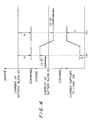
- the discharge current of the battery block 20 is set at the maximum possible value A ampere by, for example, adjusting the on-off period of the transistor 28. If the current supplied to the load 24 is as small as B ampere, as shown by a symbol (a) in Fig. 4, the current of a magnitude equivalent to the difference, namely, (A - B) ampere is supplied to the battery block 18 as a charge current.
- the electrolyte on the positive electrode side is common to the battery blocks 18 and 20
- the Br ⁇ ions dissolved reach the positive electrode of the battery block 18, receive the charge current and deposit in the electrolyte as Br2. Therefore, the concentration of Br ⁇ ions in the electrolyte is still 20%, in other words, the electrolyte is in the fully charged state.
- Zn on the electrode plate is dissolves into the electrolyte as Zn2+ ions in the battery block 20. Since the electrolyte on the negative electrode side is also common to the battery blocks 18 and 20, the Zn2+ ions dissolved reach the negative electrode of the battery block 18, receive the charge current and deposit on the electrode plate. In other words, on the negative electrode side, Zn on the electrode plate of the battery block 20 transfers onto the electrode plate of the battery block 18. Since the space between the electrode plates is generally much larger than the thickness of the layer of the deposited metal (plated layer), the deposition of Zn on the negative electrode in the battery block 18 is carried out without any obstacle. Accordingly, it is possible to fully discharge for equalization and complete dissolve Zn on the negative electrode plate even in the fully charged state.
- full discharge of a battery is possible irrespective of the state in which a power is supplied to the load and the charged state of a battery block, full discharge for equalization can be carried out at any given timing and even while the battery is out of operation.
- the charge current is detected by using a residual capacity meter for detecting the integrated value of charge and discharge current such as that described in, for example, Japanese Patent Laid-Open No. 28476/1981.
- the fully discharged state of either of the battery blocks by the above-described operation is also detected by detecting that the terminal voltage of the battery block becomes zero when the transistor is OFF.
- FIG. 5 Another embodiment of an apparatus of the present invention is shown in Fig. 5.
- This embodiment is provided with a voltage detection circuit 106 for detecting the terminal voltage of battery block 18 and the terminal voltage of the battery block 20.
- a signal from the control circuit 40 is supplied to the base of the transistor 26 or the transistor 28 in the same way as in the first embodiment, but the switch 38 provided between the control circuit 40 and the transistors 26 and 28 is controlled by a CPU 110 through an actuator 108.
- the values of the terminal voltage V18 of the battery block 18 and the terminal voltage V20 of the battery block 20 are first read by the voltage detection circuit 106. The values of V18 and V20 are compared with each other. If the terminal voltage V18 is larger than V20, it represents that the contact E of the switch 38 is closed and and a power is being transferred from the battery block 20 to the battery block 18. The terminal voltage V20 is then compared with the predetermined minimum voltage ( ⁇ 0 volt). This operation is repeated until V20 becomes smaller than the minimum value.
- the contacts of the switch 38 are switched from E to F. In this way, the transfer of the power from the battery block 20 to battery block 18 is finished, and the transfer of the power from the battery block 18 to battery block 20 is started in turn.
- V18 and V20 are compared with each other, since the contact F of the switch 38 is closed and a power is being transferred from the battery block 18 to the battery block 20, V20 is larger than V18.
- the terminal voltage V18 is then compared with the predetermined minimum voltage ( ⁇ 0 volt) When V18 becomes substantially 0 volt, the switch contacts are switched from F to E. Incidentally, it is possible to provide a predetermined suspension period in which both E and F are open immediately after V18 or V20 becomes substantially 0 volt and before the contacts are switched between E and F.
- the electrochemical cells of the battery blocks 18 and 20 are subsequently fully discharged, whereby all the electrochemical cells assume a uniform state free from deterioration. That is, it is possible to keep the amount of charge of each of the electrochemical cells constituting the battery blocks 18 and 20 uniform, as shown in Fig. 7.
- Such full discharge may be carried out not only in accordance with the detection of the terminal voltages of the battery blocks but also intermittently, for example, by the control of a timer.
- FIG. 8 Still another embodiment of an apparatus of the present invention is shown in Fig. 8. This embodiment is characterized in that a booster circuit 25A has a different structure from that of the booster circuit 25 in the first embodiment.
- One transistor 42 is adopted in place of the transistors 26 and 28 in the first embodiments.
- a signal from the control circuit 40 is supplied to the base of the transistor 42 in the same way as in the first embodiment.
- the collector and the emitter of the transistor 42 are connected to the switches 44 and 46, respectively. Therefore, if the switches 44 and 46 are connected as shown in Fig. 8, the transistor 42 constitutes a circuit for short-circuitting between the positive electrode and the negative electrode of the battery block 18. By turning on and off the transistor 42, the power remaining in the battery block 18 is transferred to the battery block 20. If the switches 44 and 46 are connected to the opposite side to the side shown in Fig. 8, the power in the battery block 20 is transferred to the battery block 18.
- a further embodiment of an apparatus of the present invention is shown in Fig. 9.
- the battery blocks 18 and 20 are disposed in parallel.
- a booster circuit 25B has a transistor 50, a boosting coil 52 and a diode 54 for transferring the power remaining in the battery block 20 to the battery block 18 and a transistor 56, a boosting coil 58 and a diode 60 for transferring a power from the battery block 18 to the battery block 20.
- the power in the battery block 20 is stored in the boosting coil 52 and then transferred to the battery block 18 through the diode 54 so as to be utilized for charging the battery block 18. If the transistor 56 is turned on and off, the power in the battery block 18 is transferred to the battery block 20.
- the diodes 62 and 64 prevent a power from flowing backward to the charger 12 during the above-described transfer of the power.
- the parallel arrangement of the battery blocks makes the control circuit slightly complicated, but brings about advantages such as a low terminal voltage and a small self discharge.
- FIG. 10 A modification of the fourth embodiment shown in Fig. 9 is shown in Fig. 10.
- the booster circuit 25 is replaced by a booster circuit 25C having a different structure.
- a transistor 70 is used in place of the transistors 50 and 56, a boosting coil 72 is used in place of the boosting coils 52 and 58 and a diode 74 is used in place of the diodes 54 and 60.
- this embodiment is provided with switches 76 and 78.
- the transfer of a power from the battery block 18 to the battery block 20 and the transfer of a power from the battery block 20 to the battery block 18 are switched from each other.
- the booster circuit 25B shown in Fig. 9 is replaced by a booster circuit 25D, and the boosting coils 52 and 58 are replaced by a boosting coil 80.
- the boosting coil 80 has a center tap 82, which is connected to a transistor 84.
- Switches 86 and 88 for bypassing the diodes 60 and 54 are provided, and by the change-over of the switches 86 and 88 the direction of the transfer of a power is switched.
- This embodiment also enables the transistors 50 and 56 and the boosting coils 52 and 58 to be replaced by one transistor and one boosting coil.
- a battery is divided into a plurality of battery blocks.
- a current flowing into a coil is rapidly changed by a switching element so as to raise the output voltage of one battery block.
- the power of the battery block is transferred to another battery block by utilizing the thus-raised voltage. This operation is subsequently repeated for each battery block.
- all the blocks are subsequently completely discharged for achieving the equalization of the amount of charge of each block.
Landscapes
- Engineering & Computer Science (AREA)
- Power Engineering (AREA)
- Transportation (AREA)
- Mechanical Engineering (AREA)
- Chemical & Material Sciences (AREA)
- General Chemical & Material Sciences (AREA)
- Sustainable Development (AREA)
- Manufacturing & Machinery (AREA)
- Life Sciences & Earth Sciences (AREA)
- Chemical Kinetics & Catalysis (AREA)
- Electrochemistry (AREA)
- Sustainable Energy (AREA)
- Charge And Discharge Circuits For Batteries Or The Like (AREA)
- Secondary Cells (AREA)
- Hybrid Cells (AREA)
- Crystals, And After-Treatments Of Crystals (AREA)
- Disintegrating Or Milling (AREA)
- Circuits Of Receivers In General (AREA)
Applications Claiming Priority (2)
| Application Number | Priority Date | Filing Date | Title |
|---|---|---|---|
| JP63164167A JPH088116B2 (ja) | 1988-07-01 | 1988-07-01 | 金属・ハロゲン電池の均等化のための完全放電方法およびこれに用いられる金属・ハロゲン電池 |
| JP164167/88 | 1988-07-01 |
Publications (3)
| Publication Number | Publication Date |
|---|---|
| EP0348983A2 true EP0348983A2 (fr) | 1990-01-03 |
| EP0348983A3 EP0348983A3 (fr) | 1991-01-23 |
| EP0348983B1 EP0348983B1 (fr) | 1994-08-31 |
Family
ID=15788001
Family Applications (1)
| Application Number | Title | Priority Date | Filing Date |
|---|---|---|---|
| EP89111880A Expired - Lifetime EP0348983B1 (fr) | 1988-07-01 | 1989-06-29 | Procédé de charge et de décharge d'une batterie et source d'énergie adoptant ce procédé |
Country Status (5)
| Country | Link |
|---|---|
| US (1) | US5177425A (fr) |
| EP (1) | EP0348983B1 (fr) |
| JP (1) | JPH088116B2 (fr) |
| AT (1) | ATE110889T1 (fr) |
| DE (1) | DE68917810T2 (fr) |
Cited By (11)
| Publication number | Priority date | Publication date | Assignee | Title |
|---|---|---|---|---|
| US5336568A (en) * | 1991-05-17 | 1994-08-09 | Alcatel Alsthom Compagnie General D'electricite | Device for optimizing the discharge of a least two electrochemical cells |
| GB2293060A (en) * | 1994-09-09 | 1996-03-13 | Ray O Vac Corp | Equalization of charge on series connected cells or batteries |
| DE19526836A1 (de) * | 1995-07-22 | 1997-01-23 | Fraunhofer Ges Forschung | Vorrichtung zum Ladungsausgleich zwischen einer Vielzahl von Energiespeichern oder -wandlern |
| US5659237A (en) * | 1995-09-28 | 1997-08-19 | Wisconsin Alumni Research Foundation | Battery charging using a transformer with a single primary winding and plural secondary windings |
| FR2777395A1 (fr) * | 1998-04-09 | 1999-10-15 | France Design | Dispositif et procede de recharge de la batterie de puissance d'un vehicule electrique |
| US6150795A (en) * | 1999-11-05 | 2000-11-21 | Power Designers, Llc | Modular battery charge equalizers and method of control |
| EP0947028A4 (fr) * | 1996-09-16 | 2001-01-24 | Suang Khuwatsamrit | Alimentation electrique et procede de protection des batteries afferentes |
| US10199694B2 (en) | 2013-03-01 | 2019-02-05 | Semiconductor Energy Laboratory Co., Ltd. | Power storage system |
| GB2565090A (en) * | 2017-08-01 | 2019-02-06 | Jaguar Land Rover Ltd | Multiple output battery system |
| GB2565091A (en) * | 2017-08-01 | 2019-02-06 | Jaguar Land Rover Ltd | Multiple output battery system with alternator architectures |
| GB2614718A (en) * | 2022-01-13 | 2023-07-19 | Mcmurtry Automotive Ltd | Battery system for an electric vehicle |
Families Citing this family (33)
| Publication number | Priority date | Publication date | Assignee | Title |
|---|---|---|---|---|
| JPH04193033A (ja) * | 1990-11-26 | 1992-07-13 | Hitachi Ltd | バッテリシステム |
| AT398142B (de) * | 1991-05-24 | 1994-09-26 | Elin Energieanwendung | Verfahren zur bestimmung des ladezustandes einer zink-brom-batterie sowie verfahren zum laden derselben |
| US5479083A (en) * | 1993-06-21 | 1995-12-26 | Ast Research, Inc. | Non-dissipative battery charger equalizer |
| US5486749A (en) * | 1993-06-21 | 1996-01-23 | Ast Research, Inc. | Multiple battery charger with a power source control |
| US5488282A (en) * | 1993-06-23 | 1996-01-30 | Hughes Aircraft Company | System and method for reconditioning spacecraft battery |
| EP0662744B1 (fr) * | 1994-01-06 | 1999-03-24 | General Motors Corporation | Dispositif et méthode d'égalisation de charge de module |
| JPH07212980A (ja) * | 1994-01-13 | 1995-08-11 | Fujitsu Ltd | バッテリの充・放電装置 |
| DE4422409C2 (de) * | 1994-06-29 | 1996-07-11 | Fraunhofer Ges Forschung | Vorrichtung zum Ladungsaustausch zwischen einer Vielzahl von in Reihe geschalteten Energiespeichern oder -wandlern |
| DE4427077C1 (de) * | 1994-07-30 | 1996-03-21 | Fraunhofer Ges Forschung | Vorrichtung zum Ladungsaustausch zwischen einer Vielzahl von in Reine geschalteten Energiespeichern oder -wandlern |
| US5850351A (en) * | 1996-04-25 | 1998-12-15 | General Motors Corporation | Distributed management apparatus for battery pack |
| US5900716A (en) * | 1997-03-03 | 1999-05-04 | Northrop Grumman Corporation | Balanced battery charger |
| US6064178A (en) * | 1998-05-07 | 2000-05-16 | Ford Motor Company | Battery charge balancing system having parallel switched energy storage elements |
| US6140800A (en) * | 1999-05-27 | 2000-10-31 | Peterson; William Anders | Autonomous battery equalization circuit |
| JP3401517B2 (ja) * | 1999-06-04 | 2003-04-28 | エヌイーシートーキン栃木株式会社 | 電池パック電源装置 |
| US7138730B2 (en) * | 2002-11-22 | 2006-11-21 | Virginia Tech Intellectual Properties, Inc. | Topologies for multiple energy sources |
| JP3638148B2 (ja) * | 2002-12-26 | 2005-04-13 | 株式会社エヌ・ティ・ティ・データ | 二次電池良否判別装置および該装置のリップル発生回路 |
| EP2270526A1 (fr) * | 2003-07-09 | 2011-01-05 | Premium Power Corporation | Dispositif de surveillance et de charge d'un groupe sélectionné d'élements de batterie |
| JP4140585B2 (ja) * | 2004-08-27 | 2008-08-27 | Fdk株式会社 | 直列接続した2次電池のバランス補正装置およびその補正方法 |
| CN101577439B (zh) * | 2005-07-28 | 2011-04-27 | 财团法人工业技术研究院 | 晶格式电池电位平衡器 |
| US20090195079A1 (en) * | 2008-01-31 | 2009-08-06 | Jens Barrenscheen | Circuit for equalizing charge unbalances in storage cells |
| JP5140470B2 (ja) * | 2008-03-25 | 2013-02-06 | Fdk株式会社 | 直列セルの電圧バランス補正回路 |
| JP5767873B2 (ja) * | 2011-06-28 | 2015-08-26 | 株式会社東芝 | 蓄電装置および蓄電システム |
| KR20130025668A (ko) * | 2011-09-02 | 2013-03-12 | 삼성전기주식회사 | 패드형 전극 접점 충전 장치 |
| FR2982089B1 (fr) * | 2011-10-26 | 2013-11-01 | Renault Sa | Procede d'equilibrage du niveau de charge et de decharge d'une batterie par commutation de ses blocs de cellules |
| US9041344B2 (en) * | 2012-05-25 | 2015-05-26 | Timotion Technology Co., Ltd. | Standby battery box for electric cylinder |
| DE102013003232B4 (de) * | 2013-02-27 | 2024-07-25 | Emh Metering Gmbh & Co. Kg | Elektrizitätszähler mit einer Batterie |
| DE102014006028B4 (de) * | 2014-04-24 | 2022-06-30 | Audi Ag | Multibatteriesystem zur Erhöhung der elektrischen Reichweite |
| US20160049883A1 (en) * | 2014-08-14 | 2016-02-18 | Google Inc. | Power-Balancing Circuits for Stacked Topologies |
| JPWO2017046900A1 (ja) * | 2015-09-16 | 2018-09-13 | 株式会社ユーパーツ | 二次電池の再生処理装置及び再生処理方法 |
| PT3356188T (pt) * | 2015-09-30 | 2020-11-23 | Relectrify Pty Ltd | Sistema de bateria |
| JP6736300B2 (ja) * | 2016-02-03 | 2020-08-05 | 株式会社デンソーテン | 電圧検出装置および電圧検出方法 |
| DE102017222192A1 (de) * | 2017-12-07 | 2019-06-13 | Audi Ag | HV-Batterieanordnung für ein Kraftfahrzeug, Bordnetz, Kraftfahrzeug und Verfahren zum Steuern einer HV-Batterieanordnung |
| CN110429705A (zh) * | 2019-08-29 | 2019-11-08 | 强文 | 一种自带ups的集成式电子信息交互装置 |
Family Cites Families (13)
| Publication number | Priority date | Publication date | Assignee | Title |
|---|---|---|---|---|
| JPS5344386B2 (fr) * | 1974-06-10 | 1978-11-28 | ||
| US3997830A (en) * | 1974-11-27 | 1976-12-14 | Rca Corporation | Satellite battery reconditioning system and method |
| US4303877A (en) * | 1978-05-05 | 1981-12-01 | Brown, Boveri & Cie Aktiengesellschaft | Circuit for protecting storage cells |
| JPS5628476A (en) * | 1979-08-14 | 1981-03-20 | Shin Kobe Electric Mach Co Ltd | Remained capacity meter for storage battery |
| DE2948700C2 (de) * | 1979-12-04 | 1983-10-20 | Brown, Boveri & Cie Ag, 6800 Mannheim | Schaltung zur Sicherung von Speicherzellen |
| JPS56132775A (en) * | 1980-03-19 | 1981-10-17 | Meidensha Electric Mfg Co Ltd | Charging and discharging of battery |
| HU185528B (en) * | 1982-05-14 | 1985-02-28 | Albert Bileczky | Method and apparatus for energy economic charging and diacharging accumulators |
| US4564798A (en) * | 1982-10-06 | 1986-01-14 | Escutcheon Associates | Battery performance control |
| DE3326729A1 (de) * | 1983-07-25 | 1985-02-07 | Siemens AG, 1000 Berlin und 8000 München | Verfahren zum betrieb eines elektrochemischen speichers |
| JPS60124371A (ja) * | 1983-12-07 | 1985-07-03 | Meidensha Electric Mfg Co Ltd | 二次電池の運転方法 |
| JPS60124372A (ja) * | 1983-12-07 | 1985-07-03 | Meidensha Electric Mfg Co Ltd | 二次電池の運転方法 |
| JPS61290669A (ja) * | 1985-06-19 | 1986-12-20 | Meidensha Electric Mfg Co Ltd | 亜鉛―ハロゲン二次電池の運転方法 |
| JPS62144066A (ja) * | 1985-12-18 | 1987-06-27 | Hitachi Ltd | 超音波探傷装置 |
-
1988
- 1988-07-01 JP JP63164167A patent/JPH088116B2/ja not_active Expired - Lifetime
-
1989
- 1989-06-28 US US07/372,601 patent/US5177425A/en not_active Expired - Fee Related
- 1989-06-29 EP EP89111880A patent/EP0348983B1/fr not_active Expired - Lifetime
- 1989-06-29 DE DE68917810T patent/DE68917810T2/de not_active Expired - Fee Related
- 1989-06-29 AT AT89111880T patent/ATE110889T1/de not_active IP Right Cessation
Cited By (16)
| Publication number | Priority date | Publication date | Assignee | Title |
|---|---|---|---|---|
| US5336568A (en) * | 1991-05-17 | 1994-08-09 | Alcatel Alsthom Compagnie General D'electricite | Device for optimizing the discharge of a least two electrochemical cells |
| GB2293060A (en) * | 1994-09-09 | 1996-03-13 | Ray O Vac Corp | Equalization of charge on series connected cells or batteries |
| US5594320A (en) * | 1994-09-09 | 1997-01-14 | Rayovac Corporation | Charge equalization of series connected cells or batteries |
| DE19526836A1 (de) * | 1995-07-22 | 1997-01-23 | Fraunhofer Ges Forschung | Vorrichtung zum Ladungsausgleich zwischen einer Vielzahl von Energiespeichern oder -wandlern |
| WO1997004513A1 (fr) * | 1995-07-22 | 1997-02-06 | Fraunhofer-Gesellschaft zur Förderung der angewandten Forschung e.V. | Dispositif d'equilibrage de charge entre une pluralite d'accumulateurs ou de convertisseurs d'energie |
| DE19526836C2 (de) * | 1995-07-22 | 1998-07-02 | Fraunhofer Ges Forschung | Vorrichtung zum Ladungsausgleich zwischen wenigstens zwei Energiespeichern oder -wandlern |
| US5659237A (en) * | 1995-09-28 | 1997-08-19 | Wisconsin Alumni Research Foundation | Battery charging using a transformer with a single primary winding and plural secondary windings |
| EP0947028A4 (fr) * | 1996-09-16 | 2001-01-24 | Suang Khuwatsamrit | Alimentation electrique et procede de protection des batteries afferentes |
| FR2777395A1 (fr) * | 1998-04-09 | 1999-10-15 | France Design | Dispositif et procede de recharge de la batterie de puissance d'un vehicule electrique |
| US6150795A (en) * | 1999-11-05 | 2000-11-21 | Power Designers, Llc | Modular battery charge equalizers and method of control |
| US10199694B2 (en) | 2013-03-01 | 2019-02-05 | Semiconductor Energy Laboratory Co., Ltd. | Power storage system |
| GB2565090A (en) * | 2017-08-01 | 2019-02-06 | Jaguar Land Rover Ltd | Multiple output battery system |
| GB2565091A (en) * | 2017-08-01 | 2019-02-06 | Jaguar Land Rover Ltd | Multiple output battery system with alternator architectures |
| GB2565090B (en) * | 2017-08-01 | 2020-04-22 | Jaguar Land Rover Ltd | Multiple output battery system |
| GB2614718A (en) * | 2022-01-13 | 2023-07-19 | Mcmurtry Automotive Ltd | Battery system for an electric vehicle |
| GB2614718B (en) * | 2022-01-13 | 2024-10-02 | Mcmurtry Automotive Ltd | Battery system for an electric vehicle |
Also Published As
| Publication number | Publication date |
|---|---|
| JPH0215580A (ja) | 1990-01-19 |
| US5177425A (en) | 1993-01-05 |
| DE68917810D1 (de) | 1994-10-06 |
| JPH088116B2 (ja) | 1996-01-29 |
| EP0348983B1 (fr) | 1994-08-31 |
| ATE110889T1 (de) | 1994-09-15 |
| DE68917810T2 (de) | 1995-01-19 |
| EP0348983A3 (fr) | 1991-01-23 |
Similar Documents
| Publication | Publication Date | Title |
|---|---|---|
| US5177425A (en) | Method of charging and discharging battery and power source apparatus adopting the same | |
| US11011920B2 (en) | Energy storage apparatus for engine start-up, method for controlling the same, and vehicle | |
| US6828757B2 (en) | Circuit for adjusting charging rate of cells in combination | |
| US6781343B1 (en) | Hybrid power supply device | |
| JP3389670B2 (ja) | 2次電池の直列接続回路 | |
| JP3706565B2 (ja) | ハイブリッドカー用の電源装置 | |
| US3987352A (en) | Method of charging storage battery in power supply system having another battery of larger capacity | |
| US9413037B2 (en) | Cell capacity adjusting device | |
| KR102575558B1 (ko) | 전기 차량의 트랙션 배터리의 충전 레벨을 제어하는 방법 및 장치 | |
| CN113767544A (zh) | 用于控制并联多电池组中包括的开关单元的接通操作的装置和方法 | |
| JPH10257683A (ja) | 組電池の充放電回路 | |
| JP2012182857A (ja) | 直流電源装置 | |
| US12596154B2 (en) | Battery system and method for controlling a battery system | |
| JP3419115B2 (ja) | 組電池の充放電保護装置 | |
| JP2000270483A (ja) | 組電池の充電状態制御装置 | |
| WO2019008367A1 (fr) | Gestion de batterie | |
| JP2002142375A (ja) | 蓄電装置およびその制御方法 | |
| KR101423703B1 (ko) | 배터리 셀 전하 균등 시스템 및 방법 | |
| JPH08163786A (ja) | 組電池の充電制御方法及び充電制御装置 | |
| JP2609854B2 (ja) | 太陽光発電システムの蓄電池充放電制御方式 | |
| CN108923088B (zh) | 蓄电池放电能力提升装置及方法 | |
| CN108615954B (zh) | 一种提高新能源电动汽车电池输出效率的方法 | |
| US20120146589A1 (en) | Method and Device For Charging Lithium-Cobalt Cells | |
| EP4395116A1 (fr) | Dispositif d'équilibrage actif | |
| KR102219920B1 (ko) | 배터리 제어 장치 및 이를 포함하는 산업 차량 |
Legal Events
| Date | Code | Title | Description |
|---|---|---|---|
| PUAI | Public reference made under article 153(3) epc to a published international application that has entered the european phase |
Free format text: ORIGINAL CODE: 0009012 |
|
| AK | Designated contracting states |
Kind code of ref document: A2 Designated state(s): AT DE FR GB |
|
| PUAL | Search report despatched |
Free format text: ORIGINAL CODE: 0009013 |
|
| AK | Designated contracting states |
Kind code of ref document: A3 Designated state(s): AT DE FR GB |
|
| 17P | Request for examination filed |
Effective date: 19910215 |
|
| 17Q | First examination report despatched |
Effective date: 19930127 |
|
| GRAA | (expected) grant |
Free format text: ORIGINAL CODE: 0009210 |
|
| AK | Designated contracting states |
Kind code of ref document: B1 Designated state(s): AT DE FR GB |
|
| REF | Corresponds to: |
Ref document number: 110889 Country of ref document: AT Date of ref document: 19940915 Kind code of ref document: T |
|
| REF | Corresponds to: |
Ref document number: 68917810 Country of ref document: DE Date of ref document: 19941006 |
|
| ET | Fr: translation filed | ||
| PLBE | No opposition filed within time limit |
Free format text: ORIGINAL CODE: 0009261 |
|
| STAA | Information on the status of an ep patent application or granted ep patent |
Free format text: STATUS: NO OPPOSITION FILED WITHIN TIME LIMIT |
|
| 26N | No opposition filed | ||
| REG | Reference to a national code |
Ref country code: GB Ref legal event code: 746 Effective date: 19970901 |
|
| REG | Reference to a national code |
Ref country code: FR Ref legal event code: D6 |
|
| REG | Reference to a national code |
Ref country code: GB Ref legal event code: IF02 |
|
| PGFP | Annual fee paid to national office [announced via postgrant information from national office to epo] |
Ref country code: FR Payment date: 20020610 Year of fee payment: 14 |
|
| PGFP | Annual fee paid to national office [announced via postgrant information from national office to epo] |
Ref country code: AT Payment date: 20020612 Year of fee payment: 14 |
|
| PGFP | Annual fee paid to national office [announced via postgrant information from national office to epo] |
Ref country code: GB Payment date: 20020626 Year of fee payment: 14 |
|
| PGFP | Annual fee paid to national office [announced via postgrant information from national office to epo] |
Ref country code: DE Payment date: 20020702 Year of fee payment: 14 |
|
| PG25 | Lapsed in a contracting state [announced via postgrant information from national office to epo] |
Ref country code: GB Free format text: LAPSE BECAUSE OF NON-PAYMENT OF DUE FEES Effective date: 20030629 Ref country code: AT Free format text: LAPSE BECAUSE OF NON-PAYMENT OF DUE FEES Effective date: 20030629 |
|
| PG25 | Lapsed in a contracting state [announced via postgrant information from national office to epo] |
Ref country code: DE Free format text: LAPSE BECAUSE OF NON-PAYMENT OF DUE FEES Effective date: 20040101 |
|
| GBPC | Gb: european patent ceased through non-payment of renewal fee |
Effective date: 20030629 |
|
| PG25 | Lapsed in a contracting state [announced via postgrant information from national office to epo] |
Ref country code: FR Free format text: LAPSE BECAUSE OF NON-PAYMENT OF DUE FEES Effective date: 20040227 |
|
| REG | Reference to a national code |
Ref country code: FR Ref legal event code: ST |