EP0349076A2 - Appareil vibratoire de ménage - Google Patents
Appareil vibratoire de ménage Download PDFInfo
- Publication number
- EP0349076A2 EP0349076A2 EP89201677A EP89201677A EP0349076A2 EP 0349076 A2 EP0349076 A2 EP 0349076A2 EP 89201677 A EP89201677 A EP 89201677A EP 89201677 A EP89201677 A EP 89201677A EP 0349076 A2 EP0349076 A2 EP 0349076A2
- Authority
- EP
- European Patent Office
- Prior art keywords
- rotor
- lever
- rocker arm
- vibration device
- household
- Prior art date
- Legal status (The legal status is an assumption and is not a legal conclusion. Google has not performed a legal analysis and makes no representation as to the accuracy of the status listed.)
- Granted
Links
- 230000033001 locomotion Effects 0.000 claims abstract description 73
- 230000001360 synchronised effect Effects 0.000 claims abstract description 27
- 210000003041 ligament Anatomy 0.000 claims description 24
- 239000004033 plastic Substances 0.000 claims description 19
- 230000005415 magnetization Effects 0.000 claims description 13
- 230000010355 oscillation Effects 0.000 claims description 13
- 239000005060 rubber Substances 0.000 claims description 10
- 238000013016 damping Methods 0.000 claims description 9
- 230000006835 compression Effects 0.000 claims description 8
- 238000007906 compression Methods 0.000 claims description 8
- 230000010358 mechanical oscillation Effects 0.000 claims description 6
- 238000005516 engineering process Methods 0.000 claims description 4
- 230000000750 progressive effect Effects 0.000 claims description 4
- 238000003780 insertion Methods 0.000 claims description 3
- 230000037431 insertion Effects 0.000 claims description 3
- 238000001125 extrusion Methods 0.000 claims description 2
- 239000002184 metal Substances 0.000 claims description 2
- 229910052751 metal Inorganic materials 0.000 claims description 2
- 239000004927 clay Substances 0.000 claims 2
- 238000010276 construction Methods 0.000 description 22
- 230000004048 modification Effects 0.000 description 8
- 238000012986 modification Methods 0.000 description 8
- 230000008901 benefit Effects 0.000 description 4
- 230000007246 mechanism Effects 0.000 description 4
- 230000005540 biological transmission Effects 0.000 description 3
- 230000008859 change Effects 0.000 description 3
- 230000002349 favourable effect Effects 0.000 description 3
- 238000004519 manufacturing process Methods 0.000 description 3
- 208000019300 CLIPPERS Diseases 0.000 description 2
- XEEYBQQBJWHFJM-UHFFFAOYSA-N Iron Chemical compound [Fe] XEEYBQQBJWHFJM-UHFFFAOYSA-N 0.000 description 2
- 208000021930 chronic lymphocytic inflammation with pontine perivascular enhancement responsive to steroids Diseases 0.000 description 2
- 239000013013 elastic material Substances 0.000 description 2
- VQKWAUROYFTROF-UHFFFAOYSA-N arc-31 Chemical compound O=C1N(CCN(C)C)C2=C3C=C4OCOC4=CC3=NN=C2C2=C1C=C(OC)C(OC)=C2 VQKWAUROYFTROF-UHFFFAOYSA-N 0.000 description 1
- 239000000919 ceramic Substances 0.000 description 1
- 238000006243 chemical reaction Methods 0.000 description 1
- 210000000078 claw Anatomy 0.000 description 1
- 230000008878 coupling Effects 0.000 description 1
- 238000010168 coupling process Methods 0.000 description 1
- 238000005859 coupling reaction Methods 0.000 description 1
- 230000001419 dependent effect Effects 0.000 description 1
- 238000010586 diagram Methods 0.000 description 1
- 238000005538 encapsulation Methods 0.000 description 1
- 230000005284 excitation Effects 0.000 description 1
- 239000011888 foil Substances 0.000 description 1
- 238000002347 injection Methods 0.000 description 1
- 239000007924 injection Substances 0.000 description 1
- 238000001746 injection moulding Methods 0.000 description 1
- 230000003993 interaction Effects 0.000 description 1
- 229910052742 iron Inorganic materials 0.000 description 1
- 238000007493 shaping process Methods 0.000 description 1
- 239000000243 solution Substances 0.000 description 1
Images






Classifications
-
- B—PERFORMING OPERATIONS; TRANSPORTING
- B26—HAND CUTTING TOOLS; CUTTING; SEVERING
- B26B—HAND-HELD CUTTING TOOLS NOT OTHERWISE PROVIDED FOR
- B26B19/00—Clippers or shavers operating with a plurality of cutting edges, e.g. hair clippers, dry shavers
- B26B19/28—Drive layout for hair clippers or dry shavers, e.g. providing for electromotive drive
- B26B19/282—Motors without a rotating central drive shaft, e.g. linear motors
-
- Y—GENERAL TAGGING OF NEW TECHNOLOGICAL DEVELOPMENTS; GENERAL TAGGING OF CROSS-SECTIONAL TECHNOLOGIES SPANNING OVER SEVERAL SECTIONS OF THE IPC; TECHNICAL SUBJECTS COVERED BY FORMER USPC CROSS-REFERENCE ART COLLECTIONS [XRACs] AND DIGESTS
- Y10—TECHNICAL SUBJECTS COVERED BY FORMER USPC
- Y10T—TECHNICAL SUBJECTS COVERED BY FORMER US CLASSIFICATION
- Y10T74/00—Machine element or mechanism
- Y10T74/18—Mechanical movements
- Y10T74/18056—Rotary to or from reciprocating or oscillating
- Y10T74/18184—Crank, pitman, and lever
Definitions
- the invention relates to a household vibration device, in particular a dry shaving or hair cutting device, in which movements of a two-pole permanent magnet designed as a rotor in a stator arrangement excited by coils generate a vibration movement of a vibration tool, specifically via a lever system which is coupled to the movements of the rotor.
- a resilient spring force acting on the lever system prestressing the drive consisting of the lever system and the rotor so that the rotor can perform oscillating movements around a rest position, wherein the lever system has a double-arm rocker arm and wherein the lever system is connected to an eccentrically arranged pin of the rotor.
- Such a household vibration device in the form of a dry shaving or hair cutting device is known from DE-PS 34 04 297.
- a single-phase synchronous motor with a two-pole, permanent-magnet rotor is used.
- special dimensions and constructive measures are necessary to ensure a safe start and the stability of the movement.
- the conversion of the rotating movements of the rotor into an oscillating movement of twice the frequency of the tool, namely a lower knife, is carried out by means of a roller cam gear.
- a spring acts on the roller cam gear, which serves on the one hand to support starting and on the other hand ensures that the roller does not lift off the cam.
- a single-phase synchronous motor is smaller than an oscillating armature motor of the same power.
- the roller cam gear has large mechanical implementation losses at the contact surface of the roller and cam.
- a time measuring device with a balance spring of a clock is known.
- the spiral balance spring limits the movements of the rotor; it vibrates essentially at a frequency which depends on the mass and spring construction of the system.
- the coil is controlled electronically.
- the motor is designed in the manner of a single-phase synchronous motor; however, it is not intended or usable as a power drive for an engine.
- the air gap is symmetrical to the center line through the stator bore parallel to the stator field direction.
- an oscillating armature motor which serves to drive a hair clipper and which has a magnet system excited by alternating current, the armature of which is actuated by its alternating poles and contains a permanent magnet which, together with its pole pieces, oscillates essentially around its central axis .
- An anchor with pole pieces is complex and has a large vibration mass.
- the stator described is also of complex construction.
- the armature carries an eccentric pin which engages in a two-armed lever connected to a movable lower knife. Because in the middle position of the lever, the connecting line of the armature shaft and rocker arm through the eccentric pin runs, the oscillation frequency of the armature and the movable knife are equal to each other. When operating on a 50 Hz network, the oscillation frequency is 50 Hz.
- a first embodiment is characterized in that the two-pole, permanent magnetic and pole shoe-free rotor is arranged in the U-shaped stator of a single-phase synchronous motor, a first lever arm of the double-armed rocker arm and the rotor are connected via a connecting rod which, on the one hand, articulates by means of a push rod joint on the first lever arm and eccentrically by means of the crank pin on the rotor, the spring force prestresses the drive such that the rest position of the rotor when the stator coils are switched off coincides with the position in which the central direction of magnetization of the rotor is approximately perpendicular to the central direction of the magnetic field of the stator arrangement, - In the rest position of the rotor, the extension of the connecting line between the push rod joint and the crank pin extends through the rotor axis, as a result of which the mechanical oscillation frequency of the oscillating lever is doubled compared to that of the rotor.
- a second embodiment is characterized in that the two-pole, permanent magnetic and pole shoe-free rotor is arranged in the U-shaped stator of a single-phase synchronous motor, the first lever arm is designed as a slot converter with a longitudinal slot into which an eccentric pin of the rotor engages, - In the rest position of the rotor, the connecting line of the eccentric pin with the rotor axis and the connecting line of the rotor axis with the rocker arm bearing form a right angle, -
- the spring force biases the drive so that the rest position of the permanent magnet designed as a rotor coincides with the stator coils switched off, with the position in which the central direction of magnetization of the rotor is approximately perpendicular to the central direction of the magnetic field of the stator arrangement, as a result of which the mechanical oscillation frequency of the oscillating lever is compared to the oscillation frequency of the rotor is doubled.
- a third embodiment is characterized in that the two-pole, permanent magnetic and pole shoe-free rotor is arranged in the U-shaped stator of a single-phase synchronous motor, a first lever arm of the double-arm rocking lever and the permanent magnet rotor are connected via a connecting rod which, on the one hand, articulates by means of a push rod joint on the first lever arm and eccentrically by means of the crank pin on the rotor, -
- the spring force biases the drive so that the rest position of the rotor when the stator coils are switched off coincides with the position in which the central direction of magnetization of the rotor is approximately perpendicular to the central direction of the magnetic field of the stator arrangement, in the rest position of the rotor, the connecting line of the push rod joint with the crank pin and the connecting line of the crank pin with the rotor axis enclose an angle of approximately 90 ° , in this position the tangent to the line of movement of the push rod joint runs approximately through the crank pin, the rest position of
- a fourth embodiment is characterized in that the two-pole, permanent magnetic and pole shoe-free rotor is arranged in the U-shaped stator of a single-phase synchronous motor, the first lever arm is designed as a slot converter with a longitudinal slot into which an eccentric pin of the rotor engages, - In the rest position of the rotor, the connecting line between the rotor axis and the rocker arm bearing runs through the eccentric pin, -
- the spring force biases the drive so that the rest position of the rotor when the stator coils are switched off coincides with the position in which the mean direction of magnetization of the rotor approximately is perpendicular to the central magnetic field direction of the stator arrangement, as a result of which the mechanical oscillation frequency of the oscillating lever is the same with respect to the rotor -
- the desired vibration frequency of the rocker arm is determined by the electrical control of the coils.
- the drive of such a household vibration device has a good efficiency because there are no mechanical contact surface losses as with the roller cam gear, which is why it is also particularly suitable for battery operation.
- the known and advantageous single-phase synchronous motor can also be shown, which is economical to manufacture and has a particularly flat design. The starting difficulties are reduced because the parallel position of the rotor field and stator field can no longer occur and the dynamic behavior is unproblematic.
- the drive has a pleasant running noise.
- the simple construction of the vibratory drive is achieved with known construction components.
- the tangent to the arcuate line of motion that the push rod joint executes about the rocker arm bearing during the rocking movement runs through the rotor axis.
- the swinging movement of the lever arm has twice the basic frequency the oscillating movement of the rotor, the fundamental frequency of which is equal to the frequency of the applied voltage. This is particularly advantageous in the case of vibration dry shavers in which an oscillation frequency of 100 Hz or 120 Hz is common.
- the amplitude of the oscillating movement of the tool and thus also its center position depend on the oscillating movement of the rotor, which in turn is determined by all system parameters, such as tension, friction, spring data, etc.
- the middle position therefore changes with the operating data.
- the second dead center position of the tool is also dependent on the operating conditions.
- a nominal middle position can be defined for nominal operation with nominal data.
- the mechanical design is based on the length of the first lever arm as well as the length of the connecting rod arm and the distance of the crank pin from the rotor axis, given the initially predetermined rotor swing angle and tool swing path.
- the sum of the length of the connecting rod and the distance of the crank pin from the rotor axis is equal to the length of the first lever arm and that the connecting line of the The rocker arm bearing with the push rod joint and the connecting lines of the push rod joint and crank pin and crank pin and rotor axis lying in a line form a right angle. This enables a particularly handy and compact shape to be achieved.
- the course of the swinging movement of the lever and the tool depends not only on the swinging movement of the rotor, but also on the movement line which the push rod joint performs due to the mechanical construction.
- the tangent to the circular arc-shaped movement line, which the push rod joint executes around the rocker arm bearing during the rocking movement runs through the rotor axis when the rocker arm is in the middle position during nominal operation.
- a further advantageous embodiment of the first embodiment of the oscillating system can be achieved in that the connecting rod is made of plastic, the connecting rod joint being designed as a film hinge.
- the connecting rod is designed to be length-elastic, then the construction of the system acting as a damper can improve the movement of the system. Peak loads are balanced.
- a second two-part rocker arm with a first and a second lever arm is mounted independently of it, the two first lever arms acting on the rotor via connecting rod joints, connecting rods and crank pin joints, with both connecting rods being at a maximum when the rotor is at rest are deflected and the rocker arms are in opposite dead center positions, - Both rocker arms perform the same rocking movements, but in opposite directions, a compression spring being attached between the first two lever arms, one of the two second lever arms drives the tool and a counter-oscillating mass is attached to the other of the two second lever arms, with the aid of which vibration damping is achieved, - In the idle state of the rotor, the tangents to the lines of movement of the first two lever arms and the extension of the connecting lines of the associated push rod joints and crank pins run through the rotor axis in the maximal
- the drive is formed in such a way that the first lever arm is designed as a slot converter with a longitudinal slot into which an eccentric pin of the rotor engages.
- the first lever arm is of length-elastic design and acts on the eccentric pin without a longitudinal slot or the like.
- the length elasticity makes the length change required when the rocker arm moves.
- Such a slot converter works essentially like a drive with a connecting rod, but is easier to implement and has fewer components.
- the tool is also in the middle position when the rotor is in the rest position.
- symmetrical oscillation of the rotor around its rest position results in symmetrical oscillation of the tool around the above-defined central position with equal oscillation distances to the right and left.
- the vibration ranges themselves depend on the vibration range of the rotor.
- the fundamental wave of the vibration of the lever here has the same frequency as the vibration of the rotor, which is equal to the frequency of the applied voltage.
- Such a structure is favorable if the drive mechanism described with a two-part lever and a connecting rod, for example for reasons of standardization should be used and if frequency doubling is not required, e.g. B. if the control frequency is already 100 Hz or if the operating frequency is sufficient for the device to work. In this case, tondeuse or hair clippers are to be mentioned.
- a second two-part rocker arm with a first and a second lever arm is mounted independently of it, the two first lever arms acting on the rotor via connecting rod joints, connecting rods and crank pin joints, with both connecting rods and in the rest position of the rotor the rocker arms are in the nominal middle position, - Both levers perform the same oscillating movement, but in opposite directions, the rotor being held in the central position at rest by spring means acting on the first two lever arms, one of the two second lever arms drives the tool and a counter-oscillating mass is attached to the other of the two second lever arms, with the aid of which vibration damping is achieved, - extend in the rest condition of the rotor, the tangents to the lines of movement of the two first lever arms through the crank pins and the connecting lines of the associated push rod joints and crank pins with the connecting lines of the crank pin
- the counter-oscillating mass, on which one of the second lever arms acts is a tondeuse or an additional device of a shaving device.
- an advantageous embodiment of the third embodiment of the oscillating system can also be achieved in that the connecting rod is made of plastic, the push rod joint being designed as a film hinge.
- the connecting rod is designed to be length-elastic, the construction of the system acting as a damper can be improved. Peak loads are balanced.
- the first lever arm is of length-elastic design and engages the eccentric pin without a longitudinal slot or the like.
- the length elasticity makes the length change required when the rocker arm moves.
- Such a slot converter works essentially like a drive with a connecting rod, but is easier to implement and has fewer components.
- the rotor is mounted in a torsion spring element.
- the torsion spring element can be made of rubber or another elastic material and can replace the rotor shaft and the rotor bearing that are otherwise required.
- rocker arms require a particularly stable and low-wear construction with low tolerances, so that the noise can be kept within limits.
- the rotor is mounted in a torsion spring element.
- the torsion spring element can be made of rubber or another elastic material and can replace the otherwise required rotor shaft and the rotor bearing.
- rocker arms require a particularly stable and low-wear construction with low tolerances, so that the noise can be kept within limits.
- the rocker arm is mounted in a torsion rubber element.
- the Z. B. coaxially constructed torsion rubber element is firmly connected on the one hand with its inner fastening ring on the bearing eye and on the other hand with the outer ring on the rocker arm.
- the rubber ring in between is so elastic that the relatively small oscillation angles can develop. It is advantageous here that there are no bearing tolerances, that the system operates quietly and is of simple construction.
- the restoring force of the springs is also supported. If the rotor and / or the rocker arm are supported by means of torsion spring elements, the restoring spring forces can be dispensed with if their restoring force is sufficiently large.
- the rocker arm bearing of the rocker arm is designed as a cruciate ligament joint in plastic technology, one end of the band of which engages on the rocker arm and the other of which ends of the band engage a rocker arm bearing eye.
- a cruciate ligament joint works without bearing tolerances and is therefore inherently low in noise.
- it is manufactured using plastic injection molding technology, its construction is simpler than a mechanical bearing.
- the rocker arm bearing designed as a cruciate ligament joint is arranged on a bridge with the aid of an insertion bracket, which is supported laterally on the mounting plate.
- a special bearing bracket for the rocker arm bearing is extremely stable on the one hand, and on the other hand it has a certain deflection property with which tolerances can be compensated for.
- the first lever arm is a first leg of a geometric figure, in particular a triangle or trapezoid, with the rocker arm bearing designed as a cruciate ligament joint in the converging region of the first and second legs enclosing an angle and that the compression spring of acts on the outside of the second leg.
- the point of application of the compression spring can thus be placed in an area which is favorable for the construction of the device.
- the resilient element has a progressive characteristic. Using a progressive characteristic curve, the vibration amplitude of the vibration tool can be limited in a simple manner when the mains voltage is high.
- the motor is a two-pole single-phase synchronous motor with a permanent magnetic rotor, which has a stator bore symmetrical to the center line through the rotor axis, which runs parallel to the stator main field direction.
- the single-phase synchronous motor can be operated with DC voltage.
- the DC voltage can be made available in the form of voltage pulses. Commutation can also be carried out by mechanical means.
- the frequency of the voltage pulses is 100 Hz or 120 Hz. In this way, mechanical oscillation frequency doubling can be dispensed with.
- the pulse frequency is greater than 120 Hz, e.g. Is 360 Hz.
- the oscillation frequency of the tool can be increased, which can lead to a better work function.
- the rotor is at least partially overmolded with plastic, the crank pin being also molded on.
- the overmoulding stabilizes the ceramic rotor and allows the crank pin to be fixed in terms of manufacturing technology.
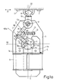
- FIG. 1a shows a single-phase synchronous motor 4 arranged on a mounting plate 3.
- This single-phase synchronous motor has a U-shaped stator iron 5 with two legs 5a and 5b. Excitation coils 6 connected in series are pushed onto the parallel legs. The free ends of the legs 5a and 5b are designed as stator poles 7.
- a two-pole, permanently magnetic rotor 9 is rotatably mounted about an axis 10.
- the rotor is preferably extrusion-coated with plastic, with the crank pin 18a also being molded on.
- the direction of magnetization of the rotor 9 is indicated by means of an arrow line 11.
- the contour 105a or 105b of the legs 5a and 5b in the region of the air gap 8 is symmetrical to the center line 110, that is to say deviates from the conventional single-phase synchronous motors and has no asymmetry.
- a double-armed lever 13 with a first lever arm 14 and a second lever arm 15 is mounted on the mounting plate 3 around a bearing eye 12.
- the free end of the first lever arm 14 has a push rod joint 16, on which a connecting rod 17 engages with one end 17a.
- the other end 17b of the connecting rod 17 is mounted on a crank pin 18 a of the rotor 9 by means of a crank pin joint 18.
- the second lever arm 15 is gripped by claws 19 of a lower knife 20 of a dry shaving device.
- the lower knife 20 is mounted by means of bearings 21 in such a way that it can execute reciprocating movements in the direction of a double arrow 22.
- first lever arm 14 engages a compression spring 23 which urges the first lever arm 14 when the single-phase synchronous motor 4 is not energized into a position in which the extension of the connecting line 24 between the push rod joint 16 and the crank pin 18a approximately by the Rotor axis 10 runs through.
- the drive In this position, the drive is in a first dead center position, in which the connecting rod is maximally deflected.
- the rotor At this first dead center position, the rotor is in a position in which its central magnetization direction, which is indicated by arrow 11, is perpendicular to the stator field direction, which is indicated by arrow 100, and approximately parallel to the center line 110.
- the rotor 9 of the single-phase synchronous motor 4 oscillates or swings back and forth, the central direction of magnetization of the rotor twisting to the left and right from one arrowhead 11a to the other arrowhead 11b.
- the compression spring 23 is so strong that the rotor 9 can not perform any orbital movement.
- the spring 23 can be a metal, plastic or rubber spring; the latter leads to a stronger damping of the drive.
- a rubber spring can limit the vibration amplitude of the rotor 9 when the mains voltage is high.
- the spring characteristic is preferably progressive.
- the lever mechanism made of double-armed lever 13 and connecting rod 17 is designed such that in the rest position of the rotor 9, the extension of the connecting line 24 between the push rod joint 16 and the crank pin 18a runs through the rotor axis 10, while at the same time a tangent 107a to the circular arc Movement line 106, which the push rod joint 16 executes about the rocker arm bearing 12a during the rocking movement, runs through the rotor axis 10.
- Fig. 1b corresponds to the embodiment of Fig. 1a with the difference that the lever gear geometry is changed such that the oscillating movement of the lever 13 is thereby further symmetrized.
- the structure is selected such that the tangent 107b to the circular arc-shaped movement line 106b, which the push rod joint 16 executes about the rocker arm bearing 12a during the rocking movement, runs through the rotor axis 10 when the rocker arm 13 is in the middle position during nominal operation.
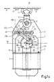
- Fig. 1c describes a further variant of the articulation of the connecting rod 17 on the rotor 9. It is provided that in the rest position of the rotor 9, the connecting line 24 of the push rod joint 16 with the crank pin 18a and the connecting line 24a of the crank pin 18a with the rotor axis 10 form an angle o include approximately 90, wherein the tangent runs 107c to the line of movement of the push rod 106c joint 16 in this position may be approximated by the crank pin 18a.
- the spring must also be designed so that it brings the rotor into the position in which its magnetization direction is perpendicular to the central stator field direction. This can be achieved, for example, with the aid of spring means 23, 23c mounted on the right and left of the first lever arm 14, which are supported on bearings 33 of the fastening plate 3.
- FIG. 2a shows another embodiment of a vibration drive for a household vibration device, which is modified compared to that according to FIGS. 1a to 1c.
- the drive contains two double-armed levers 13a and 13b with first lever arms 14a and 14b and second lever arms 15a and 15b.
- the lever arms 14a and 14b are articulated via connecting rod joints 16 and connecting rods 17a and 17b via crank pin joints 18 to crank pins 18a of the rotor 9.
- the extensions of the connecting lines 24 between the push rod joints 16 and the crank pin joints 18 of the two transmission lever halves according to FIG. 2a run through the rotor axis 10.
- the spring 23a is supported on bearing points 26 of the two lever arms 14a and 14b and thus between the arms 14a, 14b.
- the arm 14a belongs to a double-armed lever 13a with a lever arm 15a.
- the arm 14b belongs to a double-armed lever 13b with a lever arm 15b.
- the lever arm 15a acts on the lower knife 20, while the lever arm 15b is coupled to a counter-oscillating mass 20a, which is supported on arms 28 of the mounting plate 3 via damping springs 27.
- the levers 13a and 13b are mounted on the bearing eye 12.
- the vibrations of the device which are already relatively low, can be reduced even further.
- the damping springs 27 between the arms 28 of the mounting plate 3 cause further damping.
- the arrangement is such that in the rest position of the rotor 9 both connecting rods are maximally deflected and the rocker arms 13a, 13b are in opposite dead center positions that both rocker arms 13a, 13b have the same rocking motion, but in opposite directions to lead. It also applies that when the rotor 9 is at rest, the tangents 107d to the movement lines 106d of the two first lever arms 14a, 14b and the extensions of the connecting lines 24 of the associated push rod joints 16 and crank pin 18a run through the rotor axis 10 in the maximally deflected state and the arrangement in The idle state of the rotor 9 is symmetrical to the center line of the system.
- the embodiment according to FIG. 2b corresponds to the embodiment according to FIG. 2a with the exception of the articulation of the connecting rods 17a, 17b to the crank pin 18a of the rotor 9.
- the connecting rods 17a, 17b are articulated in this case in such a way that in the rest position of the rotor 9 both connecting rods 17a, 17b and the rocker arms 13a, 13b are in the nominal central position and that in the idle state of the rotor 9 the tangents 107e to the line of motion 106e of the first two lever arms 14a, 14b run through the crank pins 18a.
- the spring means consist of three springs 23a, 23d and 23e.
- the two outer springs 23d and 23e are supported on bearings 33 of the fastening plate and a respective first lever arm 14a and 14b.
- the third spring 23a is supported between the first lever arms 14a, 14b at the bearing points 26 of the lever arms.
- the connecting lines 24 of the associated push rod joints 16 and crank pin 18a and the connecting lines 24a of the crank pin 18a with the rotor axis 10 form an angle of approximately 90 ° .
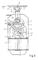
- FIG. 3 the connecting rod 17.3 compared to the connecting rod 17 of Fig. 1a to 1c and adapted to the first lever arm 14.3 modified.
- the connecting rod 17.3 consists of a plastic part which engages with a crank pin joint 18, 3 on the crank pin 18 b.
- Crank pin 18b and crank pin joint 18.3 are offset diametrically from the corresponding parts according to FIG. 1. This reverses the knife end position in the rotor rest position.
- the plastic connecting rod 17.3 is guided in an arc 31 around the rotor axis 10.
- the connecting rod 17.3 is fixed on the first lever arm 14.3 by means of a plug-in connection 32.
- the connecting rod 17.3 is designed to be length-elastic and thus shock-absorbing. Further advantages of this construction can be seen in the fact that the movement reversal proceeds more evenly and without impulsive peak loads.
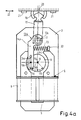
- a connecting rod is omitted in the embodiment according to FIG. 4a.
- the first lever arm 14, 4 is provided with a longitudinal slot 34a, in which the crank pin 18a engages.
- the magnetization direction in the rest position of the rotor 9 runs in the direction of the arrow 11, 4.
- the rotor is in a rest position, in which the crank pin 18a is approximately in the middle of the slot 34a.
- the arrangement is such that in the rest position of the rotor 9, the line 24b of the eccentric pin 18a with the rotor axis 10 and the line 24c of the rotor axis 10 with the rocker arm bearing 12 form a right angle.
- the rocker arm 13 to 13.4 can also be mounted as part of a modification of the drive mechanism in a torsion rubber element, the outer fastening ring of which is firmly connected to the rocker arm 13 to 13.4 and the inner fastening ring of which is fixed to the bearing eye 12.
- FIG. 4b corresponds to the embodiment according to FIG. 4a with the modification that in the rest position of the rotor 9 the line 24d between the rotor axis 10 and the rocker arm bearing 12a runs through the eccentric pin 18a. This is a version without frequency doubling.
- FIG. 4c An even simpler embodiment is described in FIG. 4c.
- the eccentric pin 18a does not move in a slot of the first lever arm 14.4.
- the change in distance between the rocker arm bearing 12a and the eccentric pin 18a that occurs during the oscillating movement is made possible in that the first lever arm 14, 4 is designed to be length-elastic.
- the line 24d runs through the rocker arm bearing 12a and the rotor axis 10 through the eccentric pin.
- FIG. 5 shows an embodiment of the drive of a vibration device in which the rocker arm bearing 12a, 5 is replaced by a cruciate ligament joint 35 the ligaments 36.
- the bearing eye 12, 5 is partly elongated partly cylindrical and is encompassed by a fastening ring 37 of the cruciate ligament joint 35.
- the cruciate ligaments 36 engage on this fastening ring 37 with first ends 38a.
- the other ends 38b of the cruciate ligaments engage the first lever arm 14.5.
- the second lever arm 15.5 of the rocking lever 13.5 takes the lower knife 20 with it and guides it along under the shaving foil 39 clamped in a shaving head 38.
- the bearing eye 12.5 is fixed on the mounting plate 3.5 via a bracket 40.
- the rocker arm 13.5 with the first lever arm 14.5 and the second lever arm 15.5 and the fastening ring 37 is injection-molded in one piece with the cruciate ligaments 36 from plastic. With this construction, the rocker arm bearing 12a, 5 results in the region of the cruciate ligaments 36. In addition, it is possible to adapt the rocker arm structure even more to the conditions with a necessary or desirable construction.
- the first lever arm 14, 5 is a first leg of a geometric figure, in particular a triangle or trapezoid, with the swing joint 35 designed as a cruciate ligament joint in the converging region of the first and second legs 14, 5, 14, which enclose an angle with one another. 5a.
- the compression spring 23 presses against the second leg 14, 5a and can be set in pressure by means of an adjustable clamp 41.
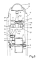
- Fig. 6 shows the drive of FIG. 5 in a side view, partially in section.
- the cut is so complicated that it was not shown in Fig. 5.
- the cut should clarify the structure and interaction of drive parts and bearings.
- the rotor 9 of the single-phase synchronous motor 4 is mounted with its axis 10 in slide bearings 41.
- the permanent magnetic rotor 9 is provided with a plastic encapsulation 42, to which the crank pin 18a is injection molded.
- Crank pin 18a and bearing shell 43 on the connecting rod 17 together form the crank pin joint 18 on the rotor.
- the push rod joint 16 is formed by an axle stub 44 at the end 17a of the connecting rod 17 and an associated bearing shell 45 on the first lever arm 14.5.
- the ends of the first lever arm 14, 5 and the cruciate ligaments 36 act on the opposite side of the parallelogram 14, 5b with their ends 38b.
- the second lever arm 15.5 has a bore which allows it to move freely around the bearing eye 12.5 which is designed as a pin in this area.
- the fastening rings 37 of the cruciate ligament joint 35 firmly enclose the bearing eye 12.5.
- the drive mechanism and the motor are fixed in the mounting plate 3, 5, and this is in turn located between the narrow side walls 46, 47 of the device housing.
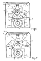
- the rocker arm 13, 7 again has the cruciate ligaments 36 already shown in FIGS. 5 and 6 in the area of the cruciate ligament joint 35. These cruciate ligaments 36, crossing one another, extend from the lever arm side 14, 7b to an insertion holder 48 on a bridge 49.
- the rocker arm 13.7 with the cruciate ligaments 36 and the bracket 48 are in one piece injected from plastic, the plastic must guarantee the elasticity of the universal joint ligaments in the region of the universal joint 35.
- the holder 48 is inserted into a plastic bridge 49, which in turn is screwed with its ends 49a and 49b to the mounting plate 3, 7 or otherwise fixed.
- a simple type of electronic control is a two-way rectified AC voltage, which is shown in Fig. 8.
- An AC mains voltage with a frequency of 50 Hz or 60 Hz is applied to the terminals 110.
- a full-wave rectifier 111 rectifies the mains AC voltage and forms a DC voltage of double frequency, ie 110 Hz or 120 Hz, indicated by the symbol 112, which is applied to the stator coils 5a, 5b.
- the oscillation frequency is doubled in this way.
Landscapes
- Life Sciences & Earth Sciences (AREA)
- Forests & Forestry (AREA)
- Engineering & Computer Science (AREA)
- Mechanical Engineering (AREA)
- Dry Shavers And Clippers (AREA)
- Reciprocating, Oscillating Or Vibrating Motors (AREA)
- Apparatuses For Generation Of Mechanical Vibrations (AREA)
- Vibration Prevention Devices (AREA)
- Food-Manufacturing Devices (AREA)
- Transmission Devices (AREA)
Priority Applications (1)
| Application Number | Priority Date | Filing Date | Title |
|---|---|---|---|
| AT89201677T ATE95105T1 (de) | 1988-07-01 | 1989-06-26 | Haushaltsvibrationsgeraet. |
Applications Claiming Priority (2)
| Application Number | Priority Date | Filing Date | Title |
|---|---|---|---|
| DE3822332A DE3822332A1 (de) | 1988-07-01 | 1988-07-01 | Haushaltsvibrationsgeraet |
| DE3822332 | 1988-07-01 |
Publications (3)
| Publication Number | Publication Date |
|---|---|
| EP0349076A2 true EP0349076A2 (fr) | 1990-01-03 |
| EP0349076A3 EP0349076A3 (fr) | 1991-04-03 |
| EP0349076B1 EP0349076B1 (fr) | 1993-09-29 |
Family
ID=6357771
Family Applications (1)
| Application Number | Title | Priority Date | Filing Date |
|---|---|---|---|
| EP89201677A Expired - Lifetime EP0349076B1 (fr) | 1988-07-01 | 1989-06-26 | Appareil vibratoire de ménage |
Country Status (9)
| Country | Link |
|---|---|
| US (1) | US5012147A (fr) |
| EP (1) | EP0349076B1 (fr) |
| JP (1) | JPH0252691A (fr) |
| CN (1) | CN1020872C (fr) |
| AT (1) | ATE95105T1 (fr) |
| DE (2) | DE3822332A1 (fr) |
| ES (1) | ES2046450T3 (fr) |
| RU (1) | RU1829992C (fr) |
| SU (1) | SU1748639A3 (fr) |
Cited By (1)
| Publication number | Priority date | Publication date | Assignee | Title |
|---|---|---|---|---|
| CN111265389A (zh) * | 2020-02-15 | 2020-06-12 | 四川大学华西医院 | 一种老年人康复锻炼拐杖 |
Families Citing this family (26)
| Publication number | Priority date | Publication date | Assignee | Title |
|---|---|---|---|---|
| JPH02252488A (ja) * | 1989-03-27 | 1990-10-11 | Matsushita Electric Works Ltd | 往復駆動装置 |
| DE4117227A1 (de) * | 1991-05-27 | 1992-12-03 | Philips Patentverwaltung | Haushaltsvibrationsgeraet mit einem vibrationsteil |
| DE4117226A1 (de) * | 1991-05-27 | 1992-12-03 | Philips Patentverwaltung | Haushaltsvibrationsgeraet mit einem vibrationsteil und einstellbarer eigenfrequenz |
| DE4117225A1 (de) * | 1991-05-27 | 1992-12-03 | Philips Patentverwaltung | Haushaltsvibrationsgeraet, insbesondere trockenrasier- oder haarschneidegeraet |
| US5524635A (en) * | 1992-09-14 | 1996-06-11 | Interventional Technologies Inc. | Apparatus for advancing a guide wire |
| US5329194A (en) * | 1992-11-23 | 1994-07-12 | Capistrano Labs, Inc. | Ultrasonic peripheral vascular probe assembly |
| US5402789A (en) * | 1992-11-23 | 1995-04-04 | Capistrano Labs, Inc. | Ultrasonic peripheral vascular probe assembly |
| US5351692A (en) * | 1993-06-09 | 1994-10-04 | Capistrano Labs Inc. | Laparoscopic ultrasonic probe |
| US5531119A (en) * | 1994-04-19 | 1996-07-02 | Capistrano Labs, Inc. | Ultrasound probe with bubble trap |
| DE19859622A1 (de) * | 1998-12-23 | 2000-07-06 | Braun Gmbh | Antriebseinrichtung für oszillierende elektrische Produkte des persönlichen Bedarfs, insbesondere Trockenrasierer |
| US6749550B1 (en) * | 2003-03-26 | 2004-06-15 | Sbl Machinery Co., Ltd. | Central drive linkage for cutting and creasing machine |
| DE102004028064A1 (de) * | 2004-06-09 | 2006-01-05 | Braun Gmbh | Elektrischer Rasierapparat mit einem schwenkbaren Scherkopf |
| DE102006004675A1 (de) * | 2006-02-02 | 2007-08-09 | Braun Gmbh | Elektrisch betriebener Rasierer |
| US7819488B2 (en) * | 2006-10-09 | 2010-10-26 | Samsung Electronics Co., Ltd. | Door opening device and refrigerator having the same |
| US7476991B2 (en) * | 2007-04-27 | 2009-01-13 | Elek Engine Corporation | Linear electromagnetic driving module and linear electromagnetic driving device |
| DE102007055843A1 (de) * | 2007-12-17 | 2009-06-25 | Hilti Aktiengesellschaft | Handwerkzeugmaschine mit Schwingungsausgleicher |
| DE202009004160U1 (de) * | 2009-03-25 | 2009-05-28 | Burgmann Industries Gmbh & Co. Kg | Thermisch entkoppelte Lageranordnung |
| JP5388188B2 (ja) * | 2009-04-23 | 2014-01-15 | 株式会社泉精器製作所 | 往復式電気かみそり |
| US8671494B2 (en) * | 2009-11-16 | 2014-03-18 | Koninklijke Philips N.V. | Low friction rotational or translational interface for a mechanical system |
| JP5453188B2 (ja) * | 2010-07-08 | 2014-03-26 | パナソニック株式会社 | 往復式電気かみそり |
| JP2012016495A (ja) * | 2010-07-08 | 2012-01-26 | Panasonic Electric Works Co Ltd | 往復式電気かみそり |
| FR2995054B1 (fr) * | 2012-08-31 | 2014-10-03 | Thales Sa | Dispositif de positionnement angulaire a trois points morts |
| US20160226364A1 (en) * | 2015-01-30 | 2016-08-04 | Sunbeam Products, Inc. | Electric Hair Clipper/Trimmer |
| JP6876506B2 (ja) * | 2017-04-27 | 2021-05-26 | マクセルホールディングス株式会社 | 電気かみそり |
| CN114257037B (zh) * | 2020-09-21 | 2023-08-04 | 北京小米移动软件有限公司 | 一种振动组件 |
| CN113682846B (zh) * | 2021-08-31 | 2022-11-25 | 安徽寒锐新材料有限公司 | 一种还原皿用传送设备 |
Family Cites Families (12)
| Publication number | Priority date | Publication date | Assignee | Title |
|---|---|---|---|---|
| GB424044A (en) * | 1933-07-13 | 1935-02-13 | Landis & Gyr A I G | An improved oscillatory armature electromotor |
| NL136196C (fr) * | 1960-09-29 | |||
| US3244916A (en) * | 1962-11-13 | 1966-04-05 | Sunbeam Corp | Rotary power device with motion conversion means |
| US3333172A (en) * | 1966-03-30 | 1967-07-25 | Harrison D Brailsford | Direct current oscillator fed motor |
| DE2032520C3 (de) * | 1970-07-01 | 1980-03-13 | Kuno Moser, Gmbh, Fabrik Fuer Feinmechanik Und Elektrotechnik, 7731 Unterkirnach | Schwingankermotor |
| DE2409592C3 (de) * | 1974-02-28 | 1980-11-13 | Braun Ag, 6000 Frankfurt | Trockenrasierapparat mit Rotationsmotor und oszillierendem Untermesser |
| AT385936B (de) * | 1980-07-28 | 1988-06-10 | Philips Nv | Trockenrasierapparat |
| DE3404299C2 (de) * | 1984-02-08 | 1986-07-17 | Philips Patentverwaltung Gmbh, 2000 Hamburg | Antriebsvorrichtung für ein Vibrationsgerät |
| DE3404297C2 (de) * | 1984-02-08 | 1986-04-17 | Philips Patentverwaltung Gmbh, 2000 Hamburg | Vorrichtung zum Antreiben eines Vibrationsteiles, insbesondere eines kleinen Haushaltsgerätes |
| DE3610770A1 (de) * | 1985-08-06 | 1987-02-19 | Philips Patentverwaltung | Antriebsvorrichtung fuer ein haushalts-vibrationsgeraet |
| JPS6266882A (ja) * | 1985-09-20 | 1987-03-26 | 松下電工株式会社 | 往復駆動装置の防振装置 |
| DE3610772C1 (de) * | 1986-03-29 | 1987-06-04 | Philips Patentverwaltung | Kleines Haushaltsgeraet,das mittels eines Einphasensynchronmotors angetrieben ist |
-
1988
- 1988-07-01 DE DE3822332A patent/DE3822332A1/de not_active Withdrawn
-
1989
- 1989-06-26 ES ES198989201677T patent/ES2046450T3/es not_active Expired - Lifetime
- 1989-06-26 EP EP89201677A patent/EP0349076B1/fr not_active Expired - Lifetime
- 1989-06-26 AT AT89201677T patent/ATE95105T1/de not_active IP Right Cessation
- 1989-06-26 DE DE89201677T patent/DE58905739D1/de not_active Expired - Fee Related
- 1989-06-27 RU SU894614553A patent/RU1829992C/ru active
- 1989-06-28 SU SU894614462A patent/SU1748639A3/ru active
- 1989-06-28 CN CN89106354A patent/CN1020872C/zh not_active Expired - Fee Related
- 1989-06-28 US US07/373,367 patent/US5012147A/en not_active Expired - Fee Related
- 1989-06-30 JP JP1167146A patent/JPH0252691A/ja active Pending
Cited By (1)
| Publication number | Priority date | Publication date | Assignee | Title |
|---|---|---|---|---|
| CN111265389A (zh) * | 2020-02-15 | 2020-06-12 | 四川大学华西医院 | 一种老年人康复锻炼拐杖 |
Also Published As
| Publication number | Publication date |
|---|---|
| SU1748639A3 (ru) | 1992-07-15 |
| CN1039551A (zh) | 1990-02-14 |
| US5012147A (en) | 1991-04-30 |
| DE3822332A1 (de) | 1990-01-04 |
| ATE95105T1 (de) | 1993-10-15 |
| EP0349076A3 (fr) | 1991-04-03 |
| EP0349076B1 (fr) | 1993-09-29 |
| JPH0252691A (ja) | 1990-02-22 |
| ES2046450T3 (es) | 1994-02-01 |
| DE58905739D1 (de) | 1993-11-04 |
| RU1829992C (ru) | 1993-07-23 |
| CN1020872C (zh) | 1993-05-26 |
Similar Documents
| Publication | Publication Date | Title |
|---|---|---|
| EP0349076B1 (fr) | Appareil vibratoire de ménage | |
| EP0313130B1 (fr) | Moteur électrique rotatif ou linéaire ayant son rotor commandé par des vibrations ultrasoniques | |
| DE602006000158T2 (de) | Linearaktuator für rollende und vibrierende Bewegung und elektrische Zahnbürste mit diesem Aktuator | |
| EP1509368B1 (fr) | Dispositif de commande concu pour generer un mouvement d'oscillation pour un petit appareil electrique | |
| DE3631120C2 (fr) | ||
| EP2262085A1 (fr) | Petit appareil électrique et unité d'entraînement électro-motorisée pour un petit appareil électrique | |
| DE10242094B4 (de) | Antriebseinrichtung zum Erzeugen einer oszillierenden Bewegung für ein elektrisches Kleingerät | |
| DE60225000T2 (de) | Linearer kompressor | |
| EP0369990A1 (fr) | Moteur alternatif à pistons tournant | |
| DE3610770C2 (fr) | ||
| EP1678812A1 (fr) | Unite d'entrainement electrique servant a generer un mouvement oscillant | |
| DE3822333A1 (de) | Kleines haushaltsvibrationsgeraet zum abschneiden von koerperhaaren | |
| DE3640398C1 (de) | Antriebsvorrichtung fuer ein kleines elektrisch angetriebenes Geraet und Verfahren zum Zusammenbau der Antriebsvorrichtung | |
| DE3404297C2 (de) | Vorrichtung zum Antreiben eines Vibrationsteiles, insbesondere eines kleinen Haushaltsgerätes | |
| EP1539438B1 (fr) | Dispositif d'entrainement destine a produire un mouvement oscillatoire pour un petit electromenager | |
| DE102008031134B4 (de) | Oszillierender Rotationsmotor sowie elektrisch betriebenes Kleingerät hierzu | |
| EP0151504B1 (fr) | Système d'entraînement à mouvement de "va-et-vient" pour petit appareil électrique | |
| DE3822334A1 (de) | Haushaltsvibrationsgeraet, insbesondere trockenrasiergeraet | |
| DE3417806A1 (de) | Vibrationstrockenrasierapparat, der mittels eines zweipoligen einphasensynchronmotors angetrieben wird | |
| DE3941847A1 (de) | Magnetenergiewandler | |
| DE3409182A1 (de) | Magnetisches antriebssystem | |
| DE4117225A1 (de) | Haushaltsvibrationsgeraet, insbesondere trockenrasier- oder haarschneidegeraet | |
| DE1081798B (de) | Elektrischer Rasierapparat | |
| DE3025708A1 (de) | Wechselstrom-kleinmotor mit pendelndem laeufer, insbesondere zum antrieb einer zahnbuerste | |
| DE4117227A1 (de) | Haushaltsvibrationsgeraet mit einem vibrationsteil |
Legal Events
| Date | Code | Title | Description |
|---|---|---|---|
| PUAI | Public reference made under article 153(3) epc to a published international application that has entered the european phase |
Free format text: ORIGINAL CODE: 0009012 |
|
| AK | Designated contracting states |
Kind code of ref document: A2 Designated state(s): AT DE ES FR GB IT |
|
| PUAL | Search report despatched |
Free format text: ORIGINAL CODE: 0009013 |
|
| AK | Designated contracting states |
Kind code of ref document: A3 Designated state(s): AT DE ES FR GB IT |
|
| 17P | Request for examination filed |
Effective date: 19910930 |
|
| 17Q | First examination report despatched |
Effective date: 19911219 |
|
| GRAA | (expected) grant |
Free format text: ORIGINAL CODE: 0009210 |
|
| AK | Designated contracting states |
Kind code of ref document: B1 Designated state(s): AT DE ES FR GB IT |
|
| REF | Corresponds to: |
Ref document number: 95105 Country of ref document: AT Date of ref document: 19931015 Kind code of ref document: T |
|
| REF | Corresponds to: |
Ref document number: 58905739 Country of ref document: DE Date of ref document: 19931104 |
|
| ITF | It: translation for a ep patent filed | ||
| GBT | Gb: translation of ep patent filed (gb section 77(6)(a)/1977) |
Effective date: 19931223 |
|
| REG | Reference to a national code |
Ref country code: ES Ref legal event code: FG2A Ref document number: 2046450 Country of ref document: ES Kind code of ref document: T3 |
|
| ET | Fr: translation filed | ||
| ITTA | It: last paid annual fee | ||
| PLBE | No opposition filed within time limit |
Free format text: ORIGINAL CODE: 0009261 |
|
| STAA | Information on the status of an ep patent application or granted ep patent |
Free format text: STATUS: NO OPPOSITION FILED WITHIN TIME LIMIT |
|
| 26N | No opposition filed | ||
| ITPR | It: changes in ownership of a european patent |
Owner name: CAMBIO RAGIONE SOCIALE;PHILIPS ELECTRONICS N.V. |
|
| PGFP | Annual fee paid to national office [announced via postgrant information from national office to epo] |
Ref country code: GB Payment date: 19950531 Year of fee payment: 7 |
|
| PGFP | Annual fee paid to national office [announced via postgrant information from national office to epo] |
Ref country code: ES Payment date: 19950605 Year of fee payment: 7 |
|
| REG | Reference to a national code |
Ref country code: FR Ref legal event code: CD |
|
| PGFP | Annual fee paid to national office [announced via postgrant information from national office to epo] |
Ref country code: FR Payment date: 19950628 Year of fee payment: 7 |
|
| PG25 | Lapsed in a contracting state [announced via postgrant information from national office to epo] |
Ref country code: GB Effective date: 19960626 |
|
| PG25 | Lapsed in a contracting state [announced via postgrant information from national office to epo] |
Ref country code: ES Free format text: LAPSE BECAUSE OF THE APPLICANT RENOUNCES Effective date: 19960627 |
|
| GBPC | Gb: european patent ceased through non-payment of renewal fee |
Effective date: 19960626 |
|
| PG25 | Lapsed in a contracting state [announced via postgrant information from national office to epo] |
Ref country code: FR Effective date: 19970228 |
|
| REG | Reference to a national code |
Ref country code: FR Ref legal event code: ST |
|
| PGFP | Annual fee paid to national office [announced via postgrant information from national office to epo] |
Ref country code: AT Payment date: 19980629 Year of fee payment: 10 |
|
| PG25 | Lapsed in a contracting state [announced via postgrant information from national office to epo] |
Ref country code: AT Free format text: LAPSE BECAUSE OF NON-PAYMENT OF DUE FEES Effective date: 19990626 |
|
| REG | Reference to a national code |
Ref country code: ES Ref legal event code: FD2A Effective date: 19991007 |
|
| PGFP | Annual fee paid to national office [announced via postgrant information from national office to epo] |
Ref country code: DE Payment date: 20010821 Year of fee payment: 13 |
|
| PG25 | Lapsed in a contracting state [announced via postgrant information from national office to epo] |
Ref country code: DE Free format text: LAPSE BECAUSE OF NON-PAYMENT OF DUE FEES Effective date: 20030101 |
|
| PG25 | Lapsed in a contracting state [announced via postgrant information from national office to epo] |
Ref country code: IT Free format text: LAPSE BECAUSE OF NON-PAYMENT OF DUE FEES;WARNING: LAPSES OF ITALIAN PATENTS WITH EFFECTIVE DATE BEFORE 2007 MAY HAVE OCCURRED AT ANY TIME BEFORE 2007. THE CORRECT EFFECTIVE DATE MAY BE DIFFERENT FROM THE ONE RECORDED. Effective date: 20050626 |