EP0349108A2 - Verfahren und Vorrichtung für die Stabilisierung einer Unterkieferprothese und eine Unterkieferprothese mit einer Stabilisierung - Google Patents
Verfahren und Vorrichtung für die Stabilisierung einer Unterkieferprothese und eine Unterkieferprothese mit einer Stabilisierung Download PDFInfo
- Publication number
- EP0349108A2 EP0349108A2 EP89304665A EP89304665A EP0349108A2 EP 0349108 A2 EP0349108 A2 EP 0349108A2 EP 89304665 A EP89304665 A EP 89304665A EP 89304665 A EP89304665 A EP 89304665A EP 0349108 A2 EP0349108 A2 EP 0349108A2
- Authority
- EP
- European Patent Office
- Prior art keywords
- appendage
- retention
- sleeve
- stabilizer
- denture
- Prior art date
- Legal status (The legal status is an assumption and is not a legal conclusion. Google has not performed a legal analysis and makes no representation as to the accuracy of the status listed.)
- Ceased
Links
Images



Classifications
-
- A—HUMAN NECESSITIES
- A61—MEDICAL OR VETERINARY SCIENCE; HYGIENE
- A61C—DENTISTRY; APPARATUS OR METHODS FOR ORAL OR DENTAL HYGIENE
- A61C13/00—Dental prostheses; Making same
- A61C13/225—Fastening prostheses in the mouth
- A61C13/24—Fastening by suction, i.e. total dentures
Definitions
- the present invention relates to a mandibular denture stabilizer, a mandibular denture incorporating such a stabilizer, and to a method of stabilizing a mandibular denture.
- Patent 1,792,226 which issued to Krasnoff on February 10, 1931 entitled "Artificial Denture” U.S. Patent 910,292 which issued to Julian on May 23, 1933 entitled “Dental Appliance” U.S. Patent 2,043,742 which issued to Fleischman on June 9, 1936 entitled “Self-Retaining Lower Denture” U.S. Patent 2,250,373 which issued to Hagerman on July 22, 1941 "Dental Plate” U.S. Patent 3,094,778 which issued to Mailland on June 25, 1963 entitled "Artificial Denture” U.S. Patent 4,609,355 which issued to Harvey on September 2, 1986 "Dental Prosthesis and Method"
- Milner's patent issued more than 60 years ago the inventor of the present invention has found no evidence that the Milner concept ever attained any significant commercial success. It is not known to be in practice currently.
- the present inventor experimented with the concept but found that while it had advantages as claimed by Milner, it had a significant disadvantage in that it did not seem to be practical in the form disclosed by Milner for commercial use or manufacture.
- the present invention seeks to reduce the deficiencies of the prior art.
- a stabilizer for a mandibular denture having an inner depending lingual flange; said stabilizer comprising anchor means for securing the stabilizer to a lingual flange, appendage means arranged to fit under a patient's tongue, and fitting means arranged to permit adjustment of the appendage means relative to the anchor means.
- a set of appendages are arranged to protrude bilaterally and medially (laterally inward) from the lingual flange. These appendages are arranged to fit under the tongue to stabilize and secure the mandibular denture in the mouth of the patient.
- the appendages extend medially from the lingual flange of the mandibular denture under the tongue of a denture wearer to receive downward pressure from the tongue and transmit that pressure to the denture base thereby providing active and passive stability to the mandibular denture.
- the appendages be made of wire because they are readily self-cleansing.
- other similar means may be used whether made of plastics or other suitable materials or whether comprising full shapes such as "plates" or flanges extending under the tongue rather than wire frames.
- the appendages will preferably be made of some material relatively inert in a patient's mouth such as stainless steel, chromium cobalt, ticonium, vitalium or titanium or gold or gold plated material.
- the adjustable fitting means of this invention may be constructed in a number of different ways using any of a variety of known adjustable mechanisms suitable for the purposes described herein and compatible with use in the mouth of a patient.
- the adjustable fitting means is found at each end of the appendage where it joins the lingual flange.
- Each such end terminates in a threaded sleeve adapted to receive a threaded shaft (or retention rod) mounted rotatably on a pintle which in turn is mounted on an anchor.
- the anchor is adapted to be bonded into the lingual flange of the mandibular denture.
- the retention rod is adapted to protrude downwardly and inwardly (medially) from the anchor and to rotate freely on the pintle.
- the sleeve is adapted to fit about a retention rod in threaded connection.
- Each rod being rotatably mounted on the pintle is adapted to be turned within a sleeve by a screwdriver or like means to advance the appendage in either direction of the longitudinal axis of the shaft.
- the appendages may be fixed to the denture by bonding the anchors to the lingual flange then the appendages may be adjusted to fit the mouth of the patient.
- the adjustable fitting mechanism may be covered with material similar to that of the lingual flange or other suitable material to set the fitting permanently.
- a dentist or dental laboratory attempting to fit the appendages into a denture need not be concerned about trying to bond the anchors in an exact position on the basis of measurements previously taken in the patient's mouth.
- the anchors of appendages may be implanted in close proximity to the optimum position and adjustments may be made after bonding of the anchors to fit the individual patient.
- the patient has an opportunity to have the appendages fitted to his mouth, to try them for a period of time and to have them readjusted, if necessary, until they are comfortable.
- the retention rods and sleeves may be covered and bonded into the lingual flange to permanently secure the fitting, to shield the mechanism from food and to protect the patient's mouth from irritation from the threaded rod.
- a gear within the sleeve which interacts with gear teeth in the surface of the retention rod.
- the gear within the sleeve may be rotated by a screwdriver or other means.
- the adjustment feature is achieved by friction fit devices of various constructions.
- the friction fit construction typically has a simpler design than the threaded shaft and sleeve embodiment and therefore the cost of manufacture is reduced.
- there is typically a collar or sleeve means which is anchored into the lingual flange by bonding it into a slot ground in the lingual flange.
- the ends of the wire frame or appendage, which may be called retention rods, are then mounted slidably within the sleeve means to be adjusted to the correct fit.
- Temporary fixation of the appendage during the adjustment procedure may be achieved by friction between the moveable parts or by fasteners affixed to the sleeve means which clamp the retention rods or catch onto notches or ridges in same. Glues or other suitable bonding material may be used to effect temporary fixation as well.
- stop means is also provided to prevent the retention rods from completely disengaging from the sleeve means to prevent the appendage from accidentally dislodging into the patient's mouth during the fitting procedure.
- the mandibular denture (1) is fitted with stabilization means comprising appendages (3) attached to the inner wall of the lingual flange (4).
- the mandibular denture (1) rests on the lower ridge or alveolar ridge of a patient along the denture fitting surface (5).
- the purpose of the stabilizing appendages (3) is to receive tongue pressure to press the mandibular denture (1) onto the gum to more securely seat the fitting surface (5) about the alveolar ridge and thereby stabilize the denture in the mouth.
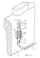
- a screw type adjustable fitting means is illustrated in Figure 2.
- Each end of the appendage (3) terminates at a threaded sleeve (7) adapted to receive a threaded shaft (9) (or retention rod) in rotatable connection.
- the threaded retention rod (9) is mounted rotatably on pintle (11) which is connected to anchor (13) and is adapted to lie within a groove (14) which is ground into the lingual flange (4).
- Each anchor (13) is adapted to be bonded into the material comprising the lingual flange (4) of the mandibular denture (1).
- Each shaft is fitted with a slot (15) adapted to receive a screwdriver for adjustment of the appendage (3) by rotation of the shafts (9).
- a mandibular denture may be fitted with the appendages (3) by embedding the anchor (13) in the lingual flange (4) in a position determined by measurements of the patient's mouth which will approximately place the appendages (3) in a comfortable position under the patient's tongue.
- the sleeves (7) may then be fitted onto shaft (9) and the appendages (3) screwed into place by using a screwdriver in slot (15) to turn the shafts (9) to move sleeves (7) along the longitudinal axis of the shafts (9).
- the denture may then be replaced in the patient's mouth and, by trial and error, adjusted to a position which the patient finds comfortable.
- the patient may then wear the mandibular denture for a number of days to assure himself that the appendages (3) are properly placed or to make such further adjustments as are necessary.
- materials similar to that of the lingual flange may be used to cover the shaft (9) and sleeve (7) to fix the setting and to protect the shaft (9) and sleeve (7) from food and to prevent irritation of the tongue from rubbing on the rough surface of shaft (9).
- appendage (3) depends from the sleeve (7) before extending laterally inward. This embodiment is useful where the lingual flange (4) does not extend downward sufficiently to use the configuration shown in Figure 2.
- the adjustable fitting means comprises a retention sleeve (20) which is adapted to slide over the ends of the appendages (which become the retention rods (21) in this embodiment) and to be located thereon by friction fit.
- the exterior sleeve wall is provided with ridges (22) to permit the retention sleeve (20) to be anchored into the lingual flange (4).
- Bonding material (23) is used to secure the sleeve (20) to the lingual flange (4).
- Notches (24) may be provided on retention rods of the appendages (3) to facilitate temporary fixation of the retention rod (21) relates to a retention sleeve (20).
- the retention sleeve (20) may be provided with a springed edge fastener (26) or like means which is adapted to catch in the notches (24) to effect fixation.
- a stop (28) is provided at the end of appendage (3) to prevent it from dislodging from the sleeve during fitting. After a comfortable fit is obtained, the whole sleeve, stop and notched portion of the retention rods may be covered with bonding material.
- the springed edge fastener (26) is dispensed with and temporary fixation during fitting is achieved by applying a drop of glue or suitable bonding material (30) to the notched shaft of the retention rods (21) at each end of the sleeve (20).
- a sleeve (40) is shown for use in this invention.
- the sleeve (40) is preferably open along part of its circumference to permit it to be snap fitted over the retention rods (21) of the appendages (3).
- Each side of the sleeve (40) has flanges (42) having ports (44) adapted to act as anchors.
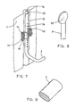
- the flanges (42) are bonded into the lingual flange (4) by bonding material (46) as shown in Figure 7.
- the ports (44) permit the bonding material (46) to bond through the flanges (42).
- a retention rod (21) is friction fitted within each sleeve (40) in slidable connection for adjustment. Temporary fixation may be achieved in the manner described above or by other known means.
- Figure 8 shows an alternative to the ball stop (28) shown in the previous Figures.
- the retention rod (21) may be flattened to provide a lug (50) to prevent slippage through the collar or sleeve means.
- FIG 9 there is illustrated a appendage (3) having an elliptical cross-section. This is a preferred cross-section in the portion of the appendage which extends under the tongue so as to present a flatter, less irritating surface to the tongue.
- Figures 10 and 11 illustrate an embodiment where the end of the appendage having the retention rod (21) is fitted within a retention sleeve (50) containing a gear (52) which may be turned by means of a slotted pin (54).
- the retention rod (21) is cut with teeth (56) adapted to gear (52) to permit the retention rod (21) to be advanced or retracted by rotating the gear (52) with slotted pin (54).
- the retention sleeve (50) may then be embedded in the lingual flange while allowing openings for the retention rod at the top and bottom of the sleeve and over the slotted pin. Then the appendage retention rods may be inserted into the sleeves and advanced to the desired location by rotating the gear with a screw driver inserted into the slotted pin. When the desired fit is obtained, the exposed areas may be covered.
- the anterior or front portion of the appendages (3) projects farther inwardly (medially) than the posterior or back portions to lessen irritation to the posterior ventral area of the patient's tongue and the floor of the mouth.
- the method of implanting a appendage means of the friction fit type in a denture comprises the steps of:
- the retention sleeves and retention rods may be covered with suitable bonding material.
Landscapes
- Health & Medical Sciences (AREA)
- Oral & Maxillofacial Surgery (AREA)
- Dentistry (AREA)
- Epidemiology (AREA)
- Life Sciences & Earth Sciences (AREA)
- Animal Behavior & Ethology (AREA)
- General Health & Medical Sciences (AREA)
- Public Health (AREA)
- Veterinary Medicine (AREA)
- Dental Prosthetics (AREA)
- Dental Tools And Instruments Or Auxiliary Dental Instruments (AREA)
Applications Claiming Priority (2)
| Application Number | Priority Date | Filing Date | Title |
|---|---|---|---|
| US192172 | 1988-05-10 | ||
| US07/192,172 US4812121A (en) | 1988-05-10 | 1988-05-10 | Mandibular denture stabilizer |
Publications (2)
| Publication Number | Publication Date |
|---|---|
| EP0349108A2 true EP0349108A2 (de) | 1990-01-03 |
| EP0349108A3 EP0349108A3 (de) | 1990-08-16 |
Family
ID=22708557
Family Applications (1)
| Application Number | Title | Priority Date | Filing Date |
|---|---|---|---|
| EP89304665A Ceased EP0349108A3 (de) | 1988-05-10 | 1989-05-09 | Verfahren und Vorrichtung für die Stabilisierung einer Unterkieferprothese und eine Unterkieferprothese mit einer Stabilisierung |
Country Status (4)
| Country | Link |
|---|---|
| US (1) | US4812121A (de) |
| EP (1) | EP0349108A3 (de) |
| AU (1) | AU615296B2 (de) |
| FI (1) | FI892261A7 (de) |
Families Citing this family (2)
| Publication number | Priority date | Publication date | Assignee | Title |
|---|---|---|---|---|
| US9566139B2 (en) * | 2013-06-06 | 2017-02-14 | Ronald Brent Kandarian | Stabilizer for lower dental appliances |
| AU2015306093B2 (en) * | 2014-08-22 | 2019-06-27 | Hibobi Pty Ltd | Passive tongue retention device |
Family Cites Families (13)
| Publication number | Priority date | Publication date | Assignee | Title |
|---|---|---|---|---|
| US1732898A (en) * | 1929-10-22 | Artificial denture | ||
| US1153486A (en) * | 1914-07-01 | 1915-09-14 | Adolphus E J Gregg | Artificial denture. |
| US1327674A (en) * | 1919-10-10 | 1920-01-13 | Hinchey Charlotte | Denture |
| US1534802A (en) * | 1923-10-02 | 1925-04-21 | Milner Fred Ewart | Lower artificial denture |
| US1801040A (en) * | 1927-03-03 | 1931-04-14 | Fogg Ernest | Artificial denture |
| US1792226A (en) * | 1928-02-20 | 1931-02-10 | Krasnoff Bernard | Artificial denture |
| US1910292A (en) * | 1932-10-21 | 1933-05-23 | James H Julian | Dental appliance |
| US2043742A (en) * | 1935-09-23 | 1936-06-09 | George W Fleischman | Self retaining lower denture |
| US2250373A (en) * | 1940-02-23 | 1941-07-22 | Royal S Hagerman | Dental plate |
| DE865787C (de) * | 1951-02-09 | 1953-02-05 | Konrad Grade | Unterkieferprothese |
| US3023499A (en) * | 1959-01-02 | 1962-03-06 | Michaelides Theophilos Paul | Device for stabilizing full lower denture |
| US3092778A (en) * | 1959-12-07 | 1963-06-04 | Philco Corp | Improved sweep integrator system |
| US4609355A (en) * | 1985-07-02 | 1986-09-02 | Harvey Sr Arthur E | Dental prosthesis and method |
-
1988
- 1988-05-10 US US07/192,172 patent/US4812121A/en not_active Expired - Fee Related
-
1989
- 1989-05-09 EP EP89304665A patent/EP0349108A3/de not_active Ceased
- 1989-05-10 AU AU34691/89A patent/AU615296B2/en not_active Ceased
- 1989-05-10 FI FI892261A patent/FI892261A7/fi not_active Application Discontinuation
Also Published As
| Publication number | Publication date |
|---|---|
| FI892261A0 (fi) | 1989-05-10 |
| AU615296B2 (en) | 1991-09-26 |
| EP0349108A3 (de) | 1990-08-16 |
| FI892261L (fi) | 1989-11-11 |
| FI892261A7 (fi) | 1989-11-11 |
| US4812121A (en) | 1989-03-14 |
| AU3469189A (en) | 1989-11-16 |
Similar Documents
| Publication | Publication Date | Title |
|---|---|---|
| US5415542A (en) | Orthodontic finishing appliance | |
| US5037295A (en) | Muscular expansion oral shield appliance | |
| CA3001485C (en) | Orthodontic assembly | |
| US4209905A (en) | Denture retention | |
| KR101025873B1 (ko) | 턱뼈에 임플란트되는 치과용 지지 임플란트 및 이를 구비한 의치 기초 보철 복합체 | |
| CA1147583A (en) | Mandibular stabilizer | |
| JP3297435B2 (ja) | 調整可能な歯移植システム | |
| US10856955B2 (en) | Orthodontic appliance for mandibular advancement | |
| US11833008B1 (en) | Dental appliance and method for adjusting and holding the position of a user's jaw to a relaxed position of the jaw | |
| CA2009440C (en) | Dental-form expansion appliance | |
| PL194869B1 (pl) | Urządzenie ortodontyczne przystosowane do dopasowywania się do wielu rozmiarów jamy ustnej i zębów, zwłaszcza dla korekty ortodontycznej | |
| US6068481A (en) | Flexible dimension temporary and long-term provisional crowns | |
| US5501598A (en) | Dental tooth system | |
| US4175322A (en) | Complete denture prostheses and method of fitting | |
| US6257892B1 (en) | Shells for temporary and provisional crowns with an hourglass shaped occlusal profile | |
| CA2343854C (en) | Self opening orthodontic appliance with opening assistance | |
| US5692521A (en) | Sleep apnea resolution appliance | |
| WO2023199327A1 (en) | Orthodontic aligner with elastomeric inner surface and rigid outer surface, and methods of orthodontic treatment with same | |
| US20100297587A1 (en) | Dental crowns | |
| US4812121A (en) | Mandibular denture stabilizer | |
| US11510767B2 (en) | Edentulous specific support and aesthetic restorative appliance | |
| US5678991A (en) | Orthodontic appliance for the correction of class III skeletal and/or dental deviations | |
| Harvey | A transitional prosthetic appliance | |
| US20210015658A1 (en) | Oral appliances, packages, systems, and components | |
| US3624904A (en) | Template for implant denture |
Legal Events
| Date | Code | Title | Description |
|---|---|---|---|
| PUAI | Public reference made under article 153(3) epc to a published international application that has entered the european phase |
Free format text: ORIGINAL CODE: 0009012 |
|
| AK | Designated contracting states |
Kind code of ref document: A2 Designated state(s): DE GB |
|
| PUAL | Search report despatched |
Free format text: ORIGINAL CODE: 0009013 |
|
| AK | Designated contracting states |
Kind code of ref document: A3 Designated state(s): DE GB |
|
| 17P | Request for examination filed |
Effective date: 19901101 |
|
| 17Q | First examination report despatched |
Effective date: 19920519 |
|
| STAA | Information on the status of an ep patent application or granted ep patent |
Free format text: STATUS: THE APPLICATION HAS BEEN REFUSED |
|
| 18R | Application refused |
Effective date: 19930705 |