EP0349264A2 - Mehrartige Verdrängerpumpe für verschiedene Flüssigkeiten - Google Patents
Mehrartige Verdrängerpumpe für verschiedene Flüssigkeiten Download PDFInfo
- Publication number
- EP0349264A2 EP0349264A2 EP89306508A EP89306508A EP0349264A2 EP 0349264 A2 EP0349264 A2 EP 0349264A2 EP 89306508 A EP89306508 A EP 89306508A EP 89306508 A EP89306508 A EP 89306508A EP 0349264 A2 EP0349264 A2 EP 0349264A2
- Authority
- EP
- European Patent Office
- Prior art keywords
- chamber
- piston
- accordance
- pistons
- pump
- Prior art date
- Legal status (The legal status is an assumption and is not a legal conclusion. Google has not performed a legal analysis and makes no representation as to the accuracy of the status listed.)
- Granted
Links
Images

Classifications
-
- F—MECHANICAL ENGINEERING; LIGHTING; HEATING; WEAPONS; BLASTING
- F04—POSITIVE - DISPLACEMENT MACHINES FOR LIQUIDS; PUMPS FOR LIQUIDS OR ELASTIC FLUIDS
- F04B—POSITIVE-DISPLACEMENT MACHINES FOR LIQUIDS; PUMPS
- F04B3/00—Machines or pumps with pistons coacting within one cylinder, e.g. multi-stage
-
- Y—GENERAL TAGGING OF NEW TECHNOLOGICAL DEVELOPMENTS; GENERAL TAGGING OF CROSS-SECTIONAL TECHNOLOGIES SPANNING OVER SEVERAL SECTIONS OF THE IPC; TECHNICAL SUBJECTS COVERED BY FORMER USPC CROSS-REFERENCE ART COLLECTIONS [XRACs] AND DIGESTS
- Y10—TECHNICAL SUBJECTS COVERED BY FORMER USPC
- Y10T—TECHNICAL SUBJECTS COVERED BY FORMER US CLASSIFICATION
- Y10T436/00—Chemistry: analytical and immunological testing
- Y10T436/25—Chemistry: analytical and immunological testing including sample preparation
- Y10T436/2575—Volumetric liquid transfer
Definitions
- two fluid displacement pumps or syringe pumps have been used to accurately meter small quantities of sample and larger quantities of reagent.
- Still another object of this invention is to provide a mixing chamber having good mixing properties and being easily cleanable and which can be useful in connection with the pump of the preceding object.
- Still another object of this invention is to provide a means and method for providing for precise measurements of first and second volumes of material in a single mixing area.
- Still another object of this invention is to provide a displacement pump in accordance with the preceding objects wherein light-weight, relatively inexpensive constructions can be used with long lasting seals and low maintenance costs in a metering and measuring environment.
- a multi-mode, differential displacement pump for obtaining at least two different measured doses with high resolution, has a first elongated chamber carrying first and second pistons therein.
- the first piston defines a first volume and is reciprocally mounted in the chamber.
- the second piston defines a second volume and is reciprocally mounted in the chamber.
- Means are provided for reciprocating the pistons as desired to obtain predetermined volume changes corresponding to movement of either or both of said first and second pistons whereby said volume changes can provide for said two different doses.
- the pistons are axially elongated and are mounted for axial movement together or separately.
- one piston axially aligned with a second piston is activated to move both pistons as one to provide a first measured dose whereupon movement of the one piston can stop while movement of the second piston continues to provide a second measured dose.
- Supplementary valving and sampling probes can be attached to the pump to provide for a wide variety of usage in metering and mixing applications.
- a single mixing chamber can be used with the pump to allow a vortex to mix the two doses.
- the use of the mixing chamber also allows cleaning of the outside of a sample carrying probe, before dilution of a sample carried in the probe, with diluent fluid in the mixing chamber.
- This invention provides the ability to obtain high resolutions for both small and large sample volumes from a single pump.
- the pump can be minimized in size.
- a single motor can be used with light-weight inexpensive construction and operation possible. Long lasting seals with lower maintenance can be employed.
- the pumps provide for variable resolution by change of components. Automatic priming and bubble removing are additional features of the invention.
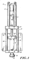
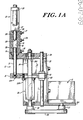
- the multi-mode differential displacement pump of this invention is shown at 10 in FIG. 1 and comprises a pump measuring section 12 connected to a stepper motor 11 through a lead screw and adjusting or dosing section 13.
- the pump measuring section 12 preferably comprises a block 15 defining a fluid-holding cylindrical chamber 16 having ports 17 and 18 for ingress and egress of fluids.
- a third port 17A can be provided for evacuation of air bubbles or other purposes if desired, although it is closed in the specific system described below.
- the chamber 16 is sealed by a stationary static seal 19 at one end and a secondary stationary static seal 20 at a second end spaced above the first end.
- a first solid piston or plunger 21 having a first diameter is reciprocally mounted within the chamber 16 and has an end 22 and butting end in contact with an end 23 of a second diameter solid piston or plunger 24 at the start of a reagent cycle.
- the pistons 21 and 24 are sealed when immobile or sliding by the stationary seals 19 and 20 respectively which also seal the chamber 16 at edge of the seals.
- seals 19 and 20 are double acting, reciprocating seals.
- Piston 24 is spring tensioned to its lower most position by spring 25 acting against end plate 26.
- the piston 24 is mounted in a linear bearing 27 and has a stop pin 28 which limits downward travel constantly urged by the spring 25.
- piston 24 which is preferably coaxially aligned with piston 21 can reciprocate in an updown direction as shown in FIG. 2 and is constantly urged downwardly but can be moved upwardly by presure acting upwardly through piston 21.
- larger diameter piston 21 can move by itself or when it abutts end 23, and is moving upwardly or downwardly, it will move along with the small diameter piston 24. It should be noted that as the pistons move within the chamber 16, the volume within the chamber 16 changes in accordance with the volume of each piston moving into and out of the chamber or in the case where piston 24 is in its lower most position, chamber 16 changes by the volume of piston 21 as it moves alone.
- the measuring section 12 is mounted on a frame formed by fixed plates 30, 30A, 33A and 33B which in turn mount a reciprocally moveable on a second plate 31 which reciprocates on guide rods 33 and screw 34A.
- a screw arrangement 34 having shaft 34A is provided with an anti-backlash nut 35 to vary the distance between plates 30 and 31 as desired so as to vary and/or limit the movement of the pistons within the chamber and thus determine the volumemetric output from the chamber in one method of adjustment.
- Piston 21 is fixed on plate 31 by bolt arrangement 31A and moves therewith.
- a sliding bearing 61 for rod 33 and mounting means for frame members 60, and assembly 34A and 35 are provided. This structure is conventional and is available from KERK Motion Products, Inc., New Hampshire, as part No. KHD6050.
- Screw shaft 34A is rotated, to move plate 31, through use of pulleys 37, 38 and drive belt 39 when the stepper motor 11 is activated. Any conventional linkage from the single electric motor 11 to the piston 21 can be used as desired.
- piston 24 has a length of 0.68 inch when fully extended in its lower most position into the chamber 16 and a diameter of 0.250 inch
- chamber 16 has a diameter of 0.265 inch and a length of 2.150 inch
- Piston 21 has a diameter of 0.2560 inch and a maximum length of travel within the chamber 16 of 1.6 inch.
- the volume of the chamber is 1500 microliters.
- the stepper motor is 1.8 °/step motor.
- the pump is operated with a constantly full chamber 15 of a liquid so that displacement of the liquid by the moving pistons in a predetermined volume can cause picking up, or discharging of a predetermined volume of the same liquid as in the pump or of another liquid in another part a constantly filled system with which the pump is used.
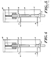
- FIGS. 2-5 show different positions of the pistons in various steps in a fluid sampling cycle in one embodiment of the invention.
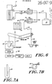
- the displacement pump 10 as shown is a system for mixing doses of fluid within a mixing chamber 100.
- the system is connected with an outlet from the dilution block to a first reactor and from it to a sensor or second reactor, a peristaltic pump and a waste area.
- a liquid sample and a liquid diluent such as a buffer can be mixed together in chamber 100.
- the buffer can be Tris buffer and the sample can be human serum or plasma for testing as in a glucose testing apparatus.
- two pinch valves 110, 111 are interconnected through tubes 112, 113 with ports 17 and 18, tubing 114, 115, preheater 116 and tubing 117 to the mixing chamber 100.
- the pump 10 is also connected through the valves 110, 111 as shown to a buffer bottle 120 through tubing 121 and to a sample probe 130 through tubing 131.
- the probe is mounted on a probe arm 132 capable of moving the probe from the dotted outline position to the full outline position as shown in FIG. 6.
- a sample vial 133 is provided in one position of the arm of the probe.
- the valves 110 and 111 act in conjunction with the pump to determine fluid flow within the system for measuring a mixing diluent (buffer) and sample (plasma) to form a dose. Doses of diluent and sample are delivered to the mixing chamber 100 from where the required mixed dosage can be provided to a testing apparatus indicated generally at 150.
- a tubular segment of air is picked up into the tubular sample probe 130.
- the air bubble formed is used so that when the sample is ultimately picked up by the probe it will not get diluted in the sample cup and it also prevents dispersion of the sample into other fluids.
- Three microlitres of air can be picked up and this is accomplished by having the components of FIG. 6 in the solid line position without the sample cup, or in any intermediate position exposed to air.
- the probe tip can be immersed in a sample which can be blood, urine, plasma, serum or the like for example.
- valve 110 is on and valve 111 is off, thus, port 200 is open to flow (open), port 201 is closed to flow (closed), port 202 is closed to flow and port 203 is open allowing an air slug to come from the probe tip through tubes 131, 114 and 113. Buffer fluid moves inwardly towards the pump port 17.
- the probe is immersed in a sample cup as shown in FIG.
- valves 110, 111 remain in the same position as discussed with respect to step 1, with the elements of the pump in the position shown in FIG. 2.
- the position of all components remains the same and another slug of air (4 microliters) is drawn into the probe with the sample cup withdrawn so that if the probe is wiped to clean it, a cloth wipe will not wick out the sample. This air gap also protects the sample when the outside of the probe is rinsed in the mixing chamber 100.
- Steps 1, 2 and 3 are carried out with both pistons in contact and moving. The pistons are in the position shown in FIG. 3.
- step four the pistons are in position shown in FIG. 4
- Tris buffer is brought from the buffer bottle 120 into the pump in an amount of for example 650 microliters to fill the chamber 16 with diluent.
- the probe is moved to the dotted outline position of FIG. 6 and positioned in the mixing chamber where the outside of the probe is washed by buffer which has been left in the mixing chamber from the previous sample.
- a peristaltic pump (not shown) can be used to drain the fluid from the mixing chamber after this step.
- valves 110 and 111 are off, i.e., port 200 is closed, 201 is open allowing flow, 202 is closed and port 203 is open allowing flow.
- step 4 the pistons are in the position shown in FIG. 4.
- 150 microliters of buffer are put into the side port 151 of the mixing chamber by opening valve 110 as well as 111 with the probe tip below the fluid level and with only the larger diameter plunger moving.
- Port 200 is open, 201 closed, 202 open and 203 closed.
- valve 110 is open, valve 111 is closed with ports 200 open, port 201 closed, port 202 closed and port 203 open allowing flow of 10 microliters of sample followed by 40 microliters of buffer acting as a diluent to wash out the sample. This is accomplished by moving piston 21 upwardly.
- a seventh step 450 microliters of buffer is put in the mixing chamber from port 151 at high velocity to cause vortex mixing and give a diluted sample.
- Valve 110 is open, valve 111 is also open with port 200 open, port 201 closed, port 202 open and port 203 closed to flow.
- the pistons are now in the positions shown in FIG. 5.
- valves 110 and 111 are both off, i.e., port 200 is closed, port 201 is open allowing flow, port 202 is closed, port 203 is open allowing flow and flow occurs from the buffer bottle to the displacement pump port 18.
- a ninth step analysis is carried out, data displayed and the mixing chamber can be emptied by the peristaltic pump.
- valve 110 is opened as is valve 111 thus port 200 is open allowing flow, port 201 is closed, port 202 is open allowing flow and port 203 is closed.
- Flow occurs through tubing 114, 115 to the mixing chamber to clean the chamber by pushing fluid from the pump to the chamber as for example 700 microliters of buffer is added to the mixing chamber 100.
- step eleven the probe is back into the mixing chamber and 60 microliters are flushed through it to clean it.
- valve 110 is opened and valve 111 is closed, i.e., ports 200 is closed allowing flow, port 201 is open, port 202 is closed and port 203 is open allowing flow.
- the sample probe is within the mixing chamber.
- valve 110, 111 are off, i.e., port 200 is closed, port 201 is open allowing flow, port 202 is closed and port 203 is open allowing flow so that drain and discharge of the mixing chamber by the peristaltic pump can occur while 300 microliters of buffer can be reloaded from the buffer bottle through lines 121 and 112 into the pump as the pump volume is displaced by movement of the plunger 21.
- FIGS. 2-5 illustrate a positioning of the pistons during the various steps in the process.
- step thirteen buffer is pushed into the mixing chamber, as for example 300 microliters, by moving the piston 21 upwardly with both valves 110 and 111 open, i.e., port 200 open to flow, port 201 closed, port 202 open and port 203 closed.
- the mixing chamber 100 of the preferred system is a stationary chamber open to the atmosphere. It is cylindrical in shape with a round circular or sectional bottom. A bottom most position outlet circular passageway allows emptying of the chamber.
- An off center inlet tube 152 as shown in FIGS. 7 and 7A provides for mixing incoming liquid with liquid within the chamber by introducing a stream of incoming liquid off the center axis of the chamber to thereby cause a swirling vortex of liquid in the chamber (use dotted arrows 153).
- the chamber has a diameter of 0.312 inch and the inlet has a diameter of 0.031 inch and enters the chamber side at an offset of 0.085 inch, i.e., it enters the chamber at the center point of a radius of the chamber at an angle of 90 degrees to the radius.
- the pistons need not be axially aligned, but are preferably positioned to be controlled by a single motor.
- two or more separate different diameter (not shown) pistons are mounted in a defined volume chamber to reciprocate independently of one another to meter more than one dose from the chamber. So long as the pistons have different volumes they have advantage to displace different fluid volumes from the pump and they can be activated by independent motors for each piston.
- the pistons react to movement of one another at least during some portion of their travel.
- the top plunger has a diameter of 0.2500 inch and is spring loaded with the bottom plunger having a diameter of 0.2560.
- the movement is accomplished up and down, by a lead screw and anti-backlash nut in accordance with a conventional linkage, although any linkage can be used as known in the art.
- the lead screw is preferably rotated by a 1.8 °/step stepper motor. The total stroke of the lead screw can be approximately 1.6 inch.
- the bottom plunger when moved all the way up to its top most position, which is the home position for the pump, (a reference point for the stepper motor using an optomechanical flag to reference the top position of the plunger). This is a sampling position as shown in FIG. 2.
- the top plunger will follow the bottom plunger because it is spring loaded and the spring force is much greater than the frictional force of the seal rubbing against the plunger.
- the diameter of the bottom plunger is bigger than the diameter of the top plunger so when the two plungers move down as one, the fluid is aspirated into the chamber as a vacuum is created.
- the volume of fluid aspirated will be ( ⁇ R12 ⁇ R22 X the distance moved downward).
- the two plungers will have to move as one for 0.250 inch. This resolution is equivalent of that of a commercially available Hamilton 100 microliter syringe pump.
- the bottom plunger When it is time to pick up reagent, the bottom plunger can be moved down so that it is no longer in contact with the top plunger.
- the top plunger has a stop at the end of its stroke.
- the volume displaced in the chamber will be equivalent to ⁇ R12X the distance moved down, which will be very large when compared to the volume displaced when the two plungers move as one.
- the plunger To aspirate 500 microliters of reagent, the plunger will have to move approximately 0.60 inch. This resolution will be equivalent to the resolution of a commercially available 2000 microliter syringe.
- the plunger will have to be moved up separately or together as one, as necessary.
- the particular pump of the preferred embodiment was designed to have a stroke of 0.62 inch for sampling and another stroke of one inch for reagent.
- piston diameters are preferably constant or at least their cross section moving within the chamber is constant.
- the right combination of diameters and stroke length will provide any desired mixing proportion desired.
- valves can be used as can three-way valves and the like.
- the pump can be used at a number of applications in a number of different system arrangements of valves and tubing as will be obvious to one skilled in the art.
- the present pump can be used to meter different quantities of sample and reagent or buffer.
- the invention can replace the need for two separate syringes or displacement pumps.
- the unique two pumps in one, design can cut hardware cost and also avoids an excessive priming cycle unlike in conventional 100 microliter pumps where often the syringe has to be removed and manually primed to rid the system of air bubbles.
- the displacement pump of this invention can be used for metering a sample in diluent or reactant as in biological analysis as when testing glucose, creatinine, cholesterol or other blood or body fluid concentrations.
- medicinal components can be admixed using the differential pump of the present invention.
- the various components can vary greatly.
- the pistons can be square, irregular shaped or round, solid or semi-solid materials can be used.
- the various seals and interconnection of the parts to move the pump may also vary as is known to those skilled in the mechanical arts.
- the pistons can be arranged so that the second piston slides into the body of the first piston as the first piston moves towards the second piston. This is in fact a reversal of elements and would accomplish the function and should be considered within the scope of this invention.
Landscapes
- Engineering & Computer Science (AREA)
- Mechanical Engineering (AREA)
- General Engineering & Computer Science (AREA)
- Reciprocating Pumps (AREA)
- Automatic Analysis And Handling Materials Therefor (AREA)
- Sampling And Sample Adjustment (AREA)
- Accessories For Mixers (AREA)
Applications Claiming Priority (2)
| Application Number | Priority Date | Filing Date | Title |
|---|---|---|---|
| US213169 | 1988-06-29 | ||
| US07/213,169 US4941808A (en) | 1988-06-29 | 1988-06-29 | Multi-mode differential fluid displacement pump |
Publications (3)
| Publication Number | Publication Date |
|---|---|
| EP0349264A2 true EP0349264A2 (de) | 1990-01-03 |
| EP0349264A3 EP0349264A3 (en) | 1990-08-08 |
| EP0349264B1 EP0349264B1 (de) | 1994-06-08 |
Family
ID=22793992
Family Applications (1)
| Application Number | Title | Priority Date | Filing Date |
|---|---|---|---|
| EP89306508A Expired - Lifetime EP0349264B1 (de) | 1988-06-29 | 1989-06-27 | Mehrartige Verdrängerpumpe für verschiedene Flüssigkeiten |
Country Status (6)
| Country | Link |
|---|---|
| US (2) | US4941808A (de) |
| EP (1) | EP0349264B1 (de) |
| JP (1) | JP2826841B2 (de) |
| AT (1) | ATE106991T1 (de) |
| DE (1) | DE68915865T2 (de) |
| ES (1) | ES2055064T3 (de) |
Cited By (2)
| Publication number | Priority date | Publication date | Assignee | Title |
|---|---|---|---|---|
| WO2005039772A3 (en) * | 2003-10-24 | 2005-07-07 | H Donald Schwartz | Pipetting module |
| EP1047928A4 (de) * | 1997-12-16 | 2006-06-14 | Waters Investments Ltd | Probennehmerspritze mit druckabdichtung |
Families Citing this family (65)
| Publication number | Priority date | Publication date | Assignee | Title |
|---|---|---|---|---|
| US5079170A (en) * | 1989-05-18 | 1992-01-07 | Quidel Corporation | Method of sample transfer using a filter applicator |
| EP0544814A1 (de) * | 1990-08-22 | 1993-06-09 | Drd Diluter Corporation | Pipette |
| US5540562A (en) * | 1994-04-28 | 1996-07-30 | Ashirus Technologies, Inc. | Single-piston, multi-mode fluid displacement pump |
| US5750906A (en) * | 1995-11-02 | 1998-05-12 | Chiron Diagnostics Corporation | Multifunction valve |
| US5720415A (en) * | 1996-04-02 | 1998-02-24 | American Medical Systems, Inc. | Apparatus for delivering fluid at a controlled rate and pressure |
| US6004117A (en) * | 1998-05-29 | 1999-12-21 | Qualicon Inc. | Displacement pump |
| WO1999063224A1 (en) * | 1998-06-02 | 1999-12-09 | Bayer Corporation | Precision pumping device |
| US5945611A (en) * | 1998-07-15 | 1999-08-31 | Welker Engineering Company | Dual piston flow-through sampler |
| US6206968B1 (en) | 1999-02-01 | 2001-03-27 | Lif Hospitality Mints Llc | Apparatus for coating products |
| EP1270938A2 (de) * | 2001-06-28 | 2003-01-02 | Esec Trading S.A. | Vorrichtung zur dosierten Abgabe einer viskosen Flüssigkeit |
| US7004407B2 (en) * | 2001-12-04 | 2006-02-28 | Mystic Tan, Inc. | Uniform metering system for spray applications |
| US20030181826A1 (en) * | 2001-12-04 | 2003-09-25 | Dave Smith | Hydrophobic/hydrophilic sample collection tip |
| US10173008B2 (en) | 2002-01-29 | 2019-01-08 | Baxter International Inc. | System and method for communicating with a dialysis machine through a network |
| US8775196B2 (en) | 2002-01-29 | 2014-07-08 | Baxter International Inc. | System and method for notification and escalation of medical data |
| US8234128B2 (en) | 2002-04-30 | 2012-07-31 | Baxter International, Inc. | System and method for verifying medical device operational parameters |
| US7018361B2 (en) | 2002-06-14 | 2006-03-28 | Baxter International Inc. | Infusion pump |
| US6997905B2 (en) | 2002-06-14 | 2006-02-14 | Baxter International Inc. | Dual orientation display for a medical device |
| US6884231B1 (en) | 2002-10-17 | 2005-04-26 | Hamilton Company | Dual chambered fluid displacement apparatus |
| US7297211B2 (en) * | 2003-05-09 | 2007-11-20 | Mystic Tan, Inc. | Single-dose spray system for application of liquids onto the human body |
| US6805015B1 (en) * | 2003-05-22 | 2004-10-19 | H. Donald Schwartz | Dual resolution syringe |
| US7396512B2 (en) | 2003-11-04 | 2008-07-08 | Drummond Scientific Company | Automatic precision non-contact open-loop fluid dispensing |
| US20050158191A1 (en) * | 2004-01-21 | 2005-07-21 | Innovative Mechanical Designs, Inc. | Highly accurate pumping device |
| US20050254972A1 (en) * | 2004-05-14 | 2005-11-17 | Baker Rodney W | Bench top pump |
| US7462242B2 (en) * | 2004-06-21 | 2008-12-09 | Mystic Tan, Inc. | Misting apparatus for electrostatic application of coating materials to body surfaces |
| US20060118039A1 (en) * | 2004-11-03 | 2006-06-08 | Cooper Steven C | Spray device with touchless controls |
| US7913938B2 (en) * | 2004-11-12 | 2011-03-29 | Mystic Tan, Inc. | Electrostatic spray nozzle with adjustable fluid tip and interchangeable components |
| US20060124779A1 (en) * | 2004-11-12 | 2006-06-15 | Cooper Steven C | Panel-mounted electrostatic spray nozzle system |
| WO2006119026A2 (en) * | 2005-04-29 | 2006-11-09 | Mystic Tan, Inc. | Gantry tower spraying system with cartridge/receptacle assembly |
| US8491525B2 (en) * | 2006-11-17 | 2013-07-23 | Ams Research Corporation | Systems, apparatus and associated methods for needleless delivery of therapeutic fluids |
| US20080167526A1 (en) * | 2007-01-08 | 2008-07-10 | Crank Justin M | Non-Occlusive, Laterally-Constrained Injection Device |
| US7850649B2 (en) | 2007-11-09 | 2010-12-14 | Ams Research Corporation | Mechanical volume control for injection devices |
| US8986253B2 (en) | 2008-01-25 | 2015-03-24 | Tandem Diabetes Care, Inc. | Two chamber pumps and related methods |
| US8057679B2 (en) | 2008-07-09 | 2011-11-15 | Baxter International Inc. | Dialysis system having trending and alert generation |
| US10089443B2 (en) | 2012-05-15 | 2018-10-02 | Baxter International Inc. | Home medical device systems and methods for therapy prescription and tracking, servicing and inventory |
| US8408421B2 (en) | 2008-09-16 | 2013-04-02 | Tandem Diabetes Care, Inc. | Flow regulating stopcocks and related methods |
| CA2737461A1 (en) | 2008-09-19 | 2010-03-25 | Tandem Diabetes Care, Inc. | Solute concentration measurement device and related methods |
| US20100111721A1 (en) * | 2008-09-25 | 2010-05-06 | Idex Health & Science Llc | Dual piston pump assembly with anti-rotation guide rails |
| US8554579B2 (en) | 2008-10-13 | 2013-10-08 | Fht, Inc. | Management, reporting and benchmarking of medication preparation |
| US8105269B2 (en) | 2008-10-24 | 2012-01-31 | Baxter International Inc. | In situ tubing measurements for infusion pumps |
| US9250106B2 (en) | 2009-02-27 | 2016-02-02 | Tandem Diabetes Care, Inc. | Methods and devices for determination of flow reservoir volume |
| US8573027B2 (en) | 2009-02-27 | 2013-11-05 | Tandem Diabetes Care, Inc. | Methods and devices for determination of flow reservoir volume |
| US8137083B2 (en) | 2009-03-11 | 2012-03-20 | Baxter International Inc. | Infusion pump actuators, system and method for controlling medical fluid flowrate |
| US8926561B2 (en) | 2009-07-30 | 2015-01-06 | Tandem Diabetes Care, Inc. | Infusion pump system with disposable cartridge having pressure venting and pressure feedback |
| US9032565B2 (en) | 2009-12-16 | 2015-05-19 | Kohler Co. | Touchless faucet assembly and method of operation |
| US8382447B2 (en) | 2009-12-31 | 2013-02-26 | Baxter International, Inc. | Shuttle pump with controlled geometry |
| US8567235B2 (en) | 2010-06-29 | 2013-10-29 | Baxter International Inc. | Tube measurement technique using linear actuator and pressure sensor |
| US9180242B2 (en) | 2012-05-17 | 2015-11-10 | Tandem Diabetes Care, Inc. | Methods and devices for multiple fluid transfer |
| KR102029974B1 (ko) | 2012-08-31 | 2019-10-08 | 백스터 코포레이션 잉글우드 | 약제 요청서 집행 시스템 및 방법 |
| EP2708288A3 (de) * | 2012-09-17 | 2015-05-06 | Sunless, Inc. | Präzisonspumpsystem für Spritzbehandlungszyklen |
| KR101695119B1 (ko) | 2012-10-26 | 2017-01-23 | 백스터 코포레이션 잉글우드 | 의료 투여분 조제 시스템을 위한 개선된 이미지 취득 |
| EP3453377B1 (de) | 2012-10-26 | 2026-04-29 | Baxter Corporation Englewood | Verbesserte arbeitsstation für medizinische dosiszubereitung |
| US9173998B2 (en) | 2013-03-14 | 2015-11-03 | Tandem Diabetes Care, Inc. | System and method for detecting occlusions in an infusion pump |
| JP2017525032A (ja) | 2014-06-30 | 2017-08-31 | バクスター・コーポレーション・イングルウッドBaxter Corporation Englewood | 管理された医療情報交換 |
| US11107574B2 (en) | 2014-09-30 | 2021-08-31 | Baxter Corporation Englewood | Management of medication preparation with formulary management |
| US11575673B2 (en) | 2014-09-30 | 2023-02-07 | Baxter Corporation Englewood | Central user management in a distributed healthcare information management system |
| EP3210183B1 (de) | 2014-10-24 | 2020-09-02 | Baxter Corporation Englewood | Automatischer austausch von gesundheitsinformationen zur einhaltung von medikamentendosierungen |
| EP3937116A1 (de) | 2014-12-05 | 2022-01-12 | Baxter Corporation Englewood | Datenanalyse für dosiszubereitung |
| CA2978455A1 (en) | 2015-03-03 | 2016-09-09 | Baxter Corporation Englewood | Pharmacy workflow management with integrated alerts |
| EP3314488B1 (de) | 2015-06-25 | 2024-03-13 | Gambro Lundia AB | Medizinisches vorrichtungssystem und verfahren mit einer verteilten datenbank |
| KR102476516B1 (ko) | 2016-12-21 | 2022-12-09 | 감브로 룬디아 아베 | 외부 도메인을 지원하는 안전한 클러스터 도메인을 구비한 정보 기술 인프라를 포함하는 의료 장치 시스템 |
| JP6814300B2 (ja) * | 2017-08-30 | 2021-01-13 | 株式会社日立ハイテク | 自動分析装置 |
| CN114901328B (zh) * | 2019-12-23 | 2024-03-19 | 阿西斯特医药系统公司 | 多流体输送系统 |
| US12046399B2 (en) * | 2022-01-27 | 2024-07-23 | Ford Global Technologies, Llc | Reduction of cracks in additively manufactured Nd—Fe—B magnet |
| US12493355B2 (en) | 2022-04-14 | 2025-12-09 | Kohler Co. | Touchless plumbing control system |
| US12553422B2 (en) | 2022-08-31 | 2026-02-17 | Fluid Metering, Inc. | Inline fluid dispense pump assembly |
Family Cites Families (27)
| Publication number | Priority date | Publication date | Assignee | Title |
|---|---|---|---|---|
| DE56635C (de) * | C. DAEVEL in Kiel | Kolbenpumpe von regelbarer Leistungsfähigkeit | ||
| DE546343C (de) * | 1928-11-16 | 1932-03-11 | Humboldt Deutzmotoren Akt Ges | Brennstoffeinspritzpumpe fuer Rohoelmotoren |
| US1983229A (en) * | 1932-11-04 | 1934-12-04 | G & J Weir Ltd | Displacement pump |
| US2396602A (en) * | 1938-08-13 | 1946-03-12 | Posch Oskar | Liquid pump |
| US2383324A (en) * | 1942-08-24 | 1945-08-21 | Clair Camille Clare Sprankl Le | Reciprocating pump |
| GB556538A (en) * | 1942-09-25 | 1943-10-08 | Cecil Cyprian Higgens | Improvements in or relating to differential pistons |
| US3168045A (en) * | 1961-09-13 | 1965-02-02 | Sebastiani Martin | Pump for thick materials |
| US3333548A (en) * | 1965-06-21 | 1967-08-01 | Prec Scient Company | Positive displacement pump |
| US3471079A (en) * | 1967-09-21 | 1969-10-07 | Elman B Myers | Reciprocating vacuum pump |
| US3695788A (en) * | 1970-01-09 | 1972-10-03 | Bernard A Loomans | Apparatus for pumping fluids |
| US3802805A (en) * | 1970-06-24 | 1974-04-09 | Otto Engineering | Pumping apparatus |
| US3704080A (en) * | 1970-07-22 | 1972-11-28 | Grosvenor M Cross | Fluid engine |
| GB1379023A (en) * | 1971-01-12 | 1975-01-02 | Dilger L | Fluid metering system |
| US4090818A (en) * | 1976-05-25 | 1978-05-23 | Hope Henry F | Adjustable metering pump |
| US4089624A (en) * | 1976-06-04 | 1978-05-16 | Becton, Dickinson And Company | Controlled pumping system |
| DK136378A (da) * | 1978-03-28 | 1979-09-29 | Foss A S | Doseringspumpe |
| DE2852994C2 (de) * | 1978-12-07 | 1981-02-05 | Boehringer Mannheim Gmbh, 6800 Mannheim | Vorrichtung zur Herstellung von Reagenslösungen |
| US4255096A (en) * | 1979-01-08 | 1981-03-10 | Baxter Travenol Laboratories, Inc. | Drive for syringe pump |
| US4566868A (en) * | 1980-09-17 | 1986-01-28 | Geotechnical Digital Systems Limited | Pressure source |
| US4610544A (en) * | 1981-09-09 | 1986-09-09 | Clifford Riley | Flow analysis |
| US4449897A (en) * | 1981-09-21 | 1984-05-22 | Garrett William R | Single-acting piston pump having two heads |
| US4493614A (en) * | 1982-10-08 | 1985-01-15 | Lifecare Services, Inc. | Pump for a portable ventilator |
| US4568249A (en) * | 1983-08-26 | 1986-02-04 | Todd James W | Variable reciprocating plunger pump |
| US4682712A (en) * | 1983-12-05 | 1987-07-28 | Boehnensieker Franz | Devices for the preparation of a mixture from at least two fluids with a definite mixture ratio |
| SE463221B (sv) * | 1985-08-21 | 1990-10-22 | Tetra Pak Ab | Doseringspump |
| JPS62225780A (ja) * | 1986-03-26 | 1987-10-03 | Noiberuku Kk | 連続作動流体装置 |
| US4815978A (en) * | 1986-04-30 | 1989-03-28 | Baxter Travenol Laboratories, Inc. | Clinical analysis methods and systems |
-
1988
- 1988-06-29 US US07/213,169 patent/US4941808A/en not_active Expired - Lifetime
-
1989
- 1989-06-27 ES ES89306508T patent/ES2055064T3/es not_active Expired - Lifetime
- 1989-06-27 AT AT89306508T patent/ATE106991T1/de not_active IP Right Cessation
- 1989-06-27 EP EP89306508A patent/EP0349264B1/de not_active Expired - Lifetime
- 1989-06-27 DE DE68915865T patent/DE68915865T2/de not_active Expired - Fee Related
- 1989-06-29 JP JP1165517A patent/JP2826841B2/ja not_active Expired - Fee Related
-
1992
- 1992-04-21 US US07/871,491 patent/US5366904A/en not_active Expired - Lifetime
Cited By (3)
| Publication number | Priority date | Publication date | Assignee | Title |
|---|---|---|---|---|
| EP1047928A4 (de) * | 1997-12-16 | 2006-06-14 | Waters Investments Ltd | Probennehmerspritze mit druckabdichtung |
| US7185551B2 (en) | 2003-05-22 | 2007-03-06 | Schwartz H Donald | Pipetting module |
| WO2005039772A3 (en) * | 2003-10-24 | 2005-07-07 | H Donald Schwartz | Pipetting module |
Also Published As
| Publication number | Publication date |
|---|---|
| JPH0249973A (ja) | 1990-02-20 |
| DE68915865D1 (de) | 1994-07-14 |
| EP0349264A3 (en) | 1990-08-08 |
| US5366904A (en) | 1994-11-22 |
| EP0349264B1 (de) | 1994-06-08 |
| ES2055064T3 (es) | 1994-08-16 |
| JP2826841B2 (ja) | 1998-11-18 |
| ATE106991T1 (de) | 1994-06-15 |
| DE68915865T2 (de) | 1994-11-10 |
| US4941808A (en) | 1990-07-17 |
Similar Documents
| Publication | Publication Date | Title |
|---|---|---|
| EP0349264B1 (de) | Mehrartige Verdrängerpumpe für verschiedene Flüssigkeiten | |
| US4323537A (en) | Analysis system | |
| US3492876A (en) | Aliquant discharge device | |
| EP0408270B1 (de) | Pipette, Pipettenrohr, diese verwendendes Probenanalysegerät und Verfahren zur Mischung und Pipettierung von Flüssigkeiten | |
| US4351799A (en) | Micrometering liquid sample dispenser | |
| US3991616A (en) | Automatic pipetter | |
| US4574850A (en) | Method of and apparatus for dispensing liquid | |
| US3831618A (en) | Apparatus for the precision metering of fluids | |
| US5817955A (en) | Apparatus for simultaneous aspiration and dispensation of fluids | |
| US20080098828A1 (en) | Apparatus for Aspirating and Dispensing Liquids in an Automated Analyzer | |
| US3273402A (en) | Specimen sampling and diluting apparatus | |
| US5183765A (en) | Means and method of measuring and dispensing | |
| US3877609A (en) | Measured dosing dispenser utilizing flow line deformer and method of dispensing | |
| CN101441223B (zh) | 具有混合功能的精密微量取样装置 | |
| US5869774A (en) | Device for taking a liquid sample | |
| US5849592A (en) | Carrierless sequential injection analysis | |
| US3726144A (en) | Synchronously programmed sample dilutor apparatus | |
| US3421858A (en) | Sampling apparatus | |
| US10768192B2 (en) | Device and method to sample liquids with high-precision in an automated sample analyzer | |
| EP0101161B1 (de) | Verfahren und Vorrichtung zur gleichzeitigen Förderung zweier Flüssigkeiten durch eine Analysenzelle | |
| CA2015983A1 (en) | Self-filling anti-siphon fluid flow system for particle analysis methods and instruments | |
| GB2126117A (en) | A self-priming volumetric diluter | |
| CN212321249U (zh) | 用于稀释微量液体样品的串联注射泵组结构 | |
| Burguera et al. | Liquid sample introduction devices in flow injection atomic spectroscopy. Invited lecture | |
| FI77579B (fi) | Mikrodoserande utdelningsanordning foer vaetskeprov. |
Legal Events
| Date | Code | Title | Description |
|---|---|---|---|
| PUAI | Public reference made under article 153(3) epc to a published international application that has entered the european phase |
Free format text: ORIGINAL CODE: 0009012 |
|
| AK | Designated contracting states |
Kind code of ref document: A2 Designated state(s): AT BE CH DE ES FR GB GR IT LI LU NL SE |
|
| 17P | Request for examination filed |
Effective date: 19900222 |
|
| R17P | Request for examination filed (corrected) |
Effective date: 19900213 |
|
| PUAL | Search report despatched |
Free format text: ORIGINAL CODE: 0009013 |
|
| AK | Designated contracting states |
Kind code of ref document: A3 Designated state(s): AT BE CH DE ES FR GB GR IT LI LU NL SE |
|
| RHK1 | Main classification (correction) |
Ipc: F04B 13/00 |
|
| 17Q | First examination report despatched |
Effective date: 19910725 |
|
| GRAA | (expected) grant |
Free format text: ORIGINAL CODE: 0009210 |
|
| AK | Designated contracting states |
Kind code of ref document: B1 Designated state(s): AT BE CH DE ES FR GB GR IT LI LU NL SE |
|
| REF | Corresponds to: |
Ref document number: 106991 Country of ref document: AT Date of ref document: 19940615 Kind code of ref document: T |
|
| PG25 | Lapsed in a contracting state [announced via postgrant information from national office to epo] |
Ref country code: LU Free format text: LAPSE BECAUSE OF NON-PAYMENT OF DUE FEES Effective date: 19940630 |
|
| REF | Corresponds to: |
Ref document number: 68915865 Country of ref document: DE Date of ref document: 19940714 |
|
| REG | Reference to a national code |
Ref country code: ES Ref legal event code: FG2A Ref document number: 2055064 Country of ref document: ES Kind code of ref document: T3 |
|
| ET | Fr: translation filed | ||
| ITF | It: translation for a ep patent filed | ||
| REG | Reference to a national code |
Ref country code: GR Ref legal event code: FG4A Free format text: 3013002 |
|
| EAL | Se: european patent in force in sweden |
Ref document number: 89306508.6 |
|
| PLBE | No opposition filed within time limit |
Free format text: ORIGINAL CODE: 0009261 |
|
| STAA | Information on the status of an ep patent application or granted ep patent |
Free format text: STATUS: NO OPPOSITION FILED WITHIN TIME LIMIT |
|
| 26N | No opposition filed | ||
| PGFP | Annual fee paid to national office [announced via postgrant information from national office to epo] |
Ref country code: AT Payment date: 19950616 Year of fee payment: 7 |
|
| PGFP | Annual fee paid to national office [announced via postgrant information from national office to epo] |
Ref country code: SE Payment date: 19950619 Year of fee payment: 7 |
|
| PGFP | Annual fee paid to national office [announced via postgrant information from national office to epo] |
Ref country code: CH Payment date: 19950622 Year of fee payment: 7 |
|
| PGFP | Annual fee paid to national office [announced via postgrant information from national office to epo] |
Ref country code: NL Payment date: 19950628 Year of fee payment: 7 |
|
| PGFP | Annual fee paid to national office [announced via postgrant information from national office to epo] |
Ref country code: GR Payment date: 19950630 Year of fee payment: 7 |
|
| PGFP | Annual fee paid to national office [announced via postgrant information from national office to epo] |
Ref country code: ES Payment date: 19950706 Year of fee payment: 7 |
|
| PGFP | Annual fee paid to national office [announced via postgrant information from national office to epo] |
Ref country code: BE Payment date: 19950807 Year of fee payment: 7 |
|
| PG25 | Lapsed in a contracting state [announced via postgrant information from national office to epo] |
Ref country code: AT Effective date: 19960627 |
|
| PG25 | Lapsed in a contracting state [announced via postgrant information from national office to epo] |
Ref country code: SE Effective date: 19960628 Ref country code: ES Free format text: LAPSE BECAUSE OF THE APPLICANT RENOUNCES Effective date: 19960628 |
|
| PG25 | Lapsed in a contracting state [announced via postgrant information from national office to epo] |
Ref country code: LI Effective date: 19960630 Ref country code: CH Effective date: 19960630 Ref country code: BE Effective date: 19960630 |
|
| BERE | Be: lapsed |
Owner name: APEC INC. Effective date: 19960630 |
|
| PG25 | Lapsed in a contracting state [announced via postgrant information from national office to epo] |
Ref country code: GR Free format text: THE PATENT HAS BEEN ANNULLED BY A DECISION OF A NATIONAL AUTHORITY Effective date: 19961231 |
|
| PG25 | Lapsed in a contracting state [announced via postgrant information from national office to epo] |
Ref country code: NL Effective date: 19970101 |
|
| REG | Reference to a national code |
Ref country code: GR Ref legal event code: MM2A Free format text: 3013002 |
|
| REG | Reference to a national code |
Ref country code: CH Ref legal event code: PL |
|
| EUG | Se: european patent has lapsed |
Ref document number: 89306508.6 |
|
| NLV4 | Nl: lapsed or anulled due to non-payment of the annual fee |
Effective date: 19970101 |
|
| REG | Reference to a national code |
Ref country code: ES Ref legal event code: FD2A Effective date: 19991102 |
|
| REG | Reference to a national code |
Ref country code: GB Ref legal event code: IF02 |
|
| PGFP | Annual fee paid to national office [announced via postgrant information from national office to epo] |
Ref country code: GB Payment date: 20021220 Year of fee payment: 14 |
|
| PG25 | Lapsed in a contracting state [announced via postgrant information from national office to epo] |
Ref country code: GB Free format text: LAPSE BECAUSE OF NON-PAYMENT OF DUE FEES Effective date: 20030627 |
|
| PGFP | Annual fee paid to national office [announced via postgrant information from national office to epo] |
Ref country code: FR Payment date: 20031231 Year of fee payment: 15 |
|
| GBPC | Gb: european patent ceased through non-payment of renewal fee |
Effective date: 20030627 |
|
| PG25 | Lapsed in a contracting state [announced via postgrant information from national office to epo] |
Ref country code: FR Free format text: LAPSE BECAUSE OF NON-PAYMENT OF DUE FEES Effective date: 20040227 |
|
| REG | Reference to a national code |
Ref country code: FR Ref legal event code: ST |
|
| PGFP | Annual fee paid to national office [announced via postgrant information from national office to epo] |
Ref country code: IT Payment date: 20060630 Year of fee payment: 18 |
|
| PGFP | Annual fee paid to national office [announced via postgrant information from national office to epo] |
Ref country code: DE Payment date: 20060731 Year of fee payment: 18 |
|
| PG25 | Lapsed in a contracting state [announced via postgrant information from national office to epo] |
Ref country code: DE Free format text: LAPSE BECAUSE OF NON-PAYMENT OF DUE FEES Effective date: 20080101 |
|
| PG25 | Lapsed in a contracting state [announced via postgrant information from national office to epo] |
Ref country code: IT Free format text: LAPSE BECAUSE OF NON-PAYMENT OF DUE FEES Effective date: 20070627 |