EP0349334A2 - Installation de lavage - Google Patents
Installation de lavage Download PDFInfo
- Publication number
- EP0349334A2 EP0349334A2 EP89306651A EP89306651A EP0349334A2 EP 0349334 A2 EP0349334 A2 EP 0349334A2 EP 89306651 A EP89306651 A EP 89306651A EP 89306651 A EP89306651 A EP 89306651A EP 0349334 A2 EP0349334 A2 EP 0349334A2
- Authority
- EP
- European Patent Office
- Prior art keywords
- jet
- cleaning apparatus
- support means
- vehicle
- cable
- Prior art date
- Legal status (The legal status is an assumption and is not a legal conclusion. Google has not performed a legal analysis and makes no representation as to the accuracy of the status listed.)
- Withdrawn
Links
Images


Classifications
-
- B—PERFORMING OPERATIONS; TRANSPORTING
- B60—VEHICLES IN GENERAL
- B60S—SERVICING, CLEANING, REPAIRING, SUPPORTING, LIFTING, OR MANOEUVRING OF VEHICLES, NOT OTHERWISE PROVIDED FOR
- B60S3/00—Vehicle cleaning apparatus not integral with vehicles
- B60S3/04—Vehicle cleaning apparatus not integral with vehicles for exteriors of land vehicles
Definitions
- the invention relates to cleaning apparatus particularly, but not exclusively, for a vehicle.
- One particular type of unit involves an arch which extends around a vehicle and which can be moved along rails so as to travel the length of the vehicle.
- the arch carries a large number of jets through which water can be fed at pressure to dislodge soiling from the vehicle.
- a high rate of water delivery is required.
- it is difficult to achieve much more than around 100 psi or so at the outlet of each jet.
- tiny outlet orifices are required which tend to create atomization of the water jet. Such atomization reduces substantially the effectiveness of the apparatus to remove heavy soiling from the vehicle.
- An object of the present invention is to provide a cleaning apparatus which substantially reduces the above difficulty.
- a cleaning apparatus for cleaning a side and/or roof of an object such as a vehicle, the apparatus including support means having an outlet such as a jet movably mounted thereon through which cleaning fluid can pass, the jet being movable along the support means.
- cleaning apparatus for cleaning a surface of a vehicle, the apparatus comprising an outlet such as a jet (herein called a "jet”) mounted on support means to enable fluid received from a supp]y to be directed towards the surface of the vehicle, characterised in that the jet is movable up and down relative to the surface to be cleaned.
- a jet herein called a "jet”
- the jet may be movable in an up and down direction.
- the jet or a carriage on which the jet is mounted is movable along an upwardly extending rail on the support means.
- the drive for the carriage may be effected by any suitable means but is preferably moved by a cable.
- the jet may be arranged for oscillation e.g., in a substantially horizontal plane as well as being movable in the up and down direction.
- a second support means is provided for a second jet through which cleaning fluid will pass for cleaning an opposite side of the object, the second jet being movable along the second support means, e.g., in the up and down direction.
- the second jet or a second carriage on which the second jet is mounted may be movable along a second upwardly extending rail.
- the two carriages may be operated by means of a motor e.g., via cabling.
- the second jet may be arranged for oscillation, e.g., in a substantially horizontal plane as well as being movable in the up and down direction.
- Fluid feed to the or each jet may be effected through a hose which extends from an outlet substantially mid-way between the ends of travel of the carriage.
- the hose is preferably no shorter than the distance between the outlet of the hose and the distance from the outlet to a limit of travel of the carriage.
- drive means may be provided for effecting such oscillation.
- the drive means may be electrically powered and power supply cable to the drive means may extend between a point mid-way between the ends of the travel of the associated carriage and, like the hose, may have a length no less than the distance between the mid-point of travel and the limit of travel of that carriage.
- the or each support means is preferably mounted upon a horizontal rail to enable it to be moved horizontally relative to a vehicle.
- the upwardly extending rail may, in such a case, be mounted on a base unit which moves along the horizontal rails.
- the or each support means is movable by cable means along its rail which can be driven from a motor.
- the cable means preferably includes a first run of cable between the drive means and a pulley and a second run of cable between the drive means and a second pulley.
- the two runs of cable are preferably independent lengths of cable each of which is wrapped around a winding drum or the like, one of which is arranged to wind off the drum as the other is being wound on. If desired, independent drums may be provided for the independent lengths of cable.
- the first pulley preferably forms a support for the electrical supply for the drive means cable which supplies the electrical power for the associated oscillating jet.
- the second pulley preferably supports the hose for the cleaning fluid.
- the electrical cable and the fluid feed hose may be connected to opposite portions of the support means so that movement of the support means along its horizontal rail in one direction will be effected through the electrical cable whilst movement of the support means in the opposite direction will be effected through the fluid feed hose.
- a substantially identical arrangement of cabling may be provided for drawing the support means for the second jet along its horizontal rail.
- the first and second sections of drive cable for the second support means may be wound around a second drum which, for convenience, may be arranged coaxial with the drum for driving the first set of cables for the first support means so as to be drivable by a common output shaft of the driving motor.
- that output shaft is an output shaft of a gearbox driven by the motor.
- the two support means may comprise upwardly extending members which may be joined at their upper ends to form an arch.
- a section joining the two upwardly extending members may carry a third jet which may be movable from side to side along the joining section for spraying cleaning fluid on to a roof of the object.
- the movement of the third jet could be effected by cable means or other suitable drive means. If cable means is used to drive the third jet, the cable means could be linked in with the cable drive for the upwardly moving first and second jets directly or via a suitable pulley system. The latter may effectively reduce the side to side movement of the further jet which will normally only need to move for part of the overall width of the object.
- the upwardly extending rail along which it travels in the up and down direction may be arranged to pivot about an axis e.g., a vertical axis. That particular feature will be useful when the jet reaches its limit of horizontal travel so that, for example, at the front end of, say, a vehicle the rail will turn slightly towards the windscreen of the vehicle so as direct a jet positively on to the front of the vehicle rather than in a forward direction clear of the vehicle thereby making full use of the cleaning fluid.
- the upwardly extending rail could pivot near the rear of the vehicle so that a very positive jet of fluid is sprayed against the vehicle rear end. It is envisaged that the rail could be arranged to pivot cyclically as the support means is moved along the upwardly extending rail to effect oscillating movement of the jet. That could be used instead of a specific drive motor for oscillating the jet as proposed above.
- the jet may be mounted on a first trolley section which is pivotally mounted upon a second trolley section engaging the upwardly extending rails. Oscillating movement of the jet can then be effected by moving the second trolley section about its pivot relative to the first trolley section on the upwardly extending rail.
- the apparatus is used in combination with a cleaning apparatus for cleaning the underside of the vehicle.
- the underside cleaning apparatus can be of the type described in our European Patent No.0100680.
- the drive means for driving the upwardly extending members along the horizontal rails could also be used to drive a carriage of the cleaning apparatus for cleaning the underside of the vehicle.
- a source of cleaning fluid may be used which is common to both sets of apparatus.
- the movement of the or each jet can be controlled by a programmable unit.
- a jet may travel, for example, its full height when cleaning the cab section of a vehicle but may have reduced vertical travel when cleaning the side of a flat bed section of the vehicle.
- the rate of cleaning can be greatly increased for a vehicle where a full vertical travel of the jet is not required for the total length of the vehicle concerned.
- the speed of travel of the jet both in the vertical and horizontal direction may also be programmable so that particularly badly soiled parts of a known vehicle can receive a more concentrated treatment by the spray to dislodge the heavy soiling whereas other sections of the vehicle which are less heavily soiled may be sprayed for a relatively shorter time.
- the system may be of a portable nature so as to be demountable and movable from one place to another or may be a specific installation fixed to a floor say, of a garage or outdoor cleaning area.
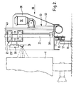
- FIG.1 two rails 10, 12 are carried by ground engaging supports 13.
- An arch 14 has two base units 15, 16 which carry opposed grooved rollers 17 which engage upper and lower surfaces of the respective rails 10, 12. The rollers 17 permit the arch 14 to be moved along the rails 10, 12 as described below.
- the arch 14 comprises vertical sides 18, 19 (constituting the aforesaid support means) and a horizontal upper section 20.
- the side 18 supports a vertical rail 22 on which a carriage 23 is movable.
- the vertical side 19 carries a vertical rail 24 on which a carriage 25 is movable.
- the carriages 23 and 25 are substantially identical and the means for effecting their movement along the rails 22, 24 is described below.
- the upper section 20 is also provided with a rail (not shown) on which a carriage 26 is movable.
- the carriage 23 includes four rollers 27 which engage opposite sides of the vertical rail 22.
- the carriage supports a spray jet 28 which can be oscillated about a vertical axis 29 by a motor 30.
- the vertical side 18 carries on its outer surface a flange 30 which carries a motor 32 arranged to transmit drive through cabling indicated generally at 33 to the carriages 23, 25.
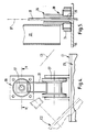
- the rail 22 is mounted at its upper and lower ends for pivotal movement about a vertical axis 37.
- Figs.2, 4 and 5 illustrate a pivotal support 38 for the lower end of the rail, the rail being formed as a box-cross section tube.
- the lower pivot comprises a cylindrical bearing member 34 mounted on the base unit 15 and which rotatably supports a reduced cross-section lower end 35 of a hollow cylindrical rail mounting 36.
- the rail mounting 36 is suitably secured to the rail 22 by means not shown.
- a suitable motor (not shown) is provided for turning the rail about the vertical axis which passes through the centre of the rail mounting 36 to enable the carriage 23 to be moved from a position C1 in Fig.4 to a position C2 or C3 indicated in Fig.4.
- the total angular movement of the carriage about axis 37 may be around 90 degrees. It will be appreciated that such angular movement about axis 37 is additional to the oscillation of the spray jet 28 about the vertical axis 29.
- Cable 31 for supplying electrical power to the motor which turns the rail passes axially through the bearing unit 34 and rail mounting 36.
- the carriage 25 and rail 24 are substantially identical to carriage 23 and rail 22 and rail 24 is mounted for pivoting in the same way as rail 22.
- the motor 32 drives a drum 40 on which is wound a length of first cable 42 and a length of second cable 43.
- the cable 42 passes from the drum 40 around a first pulley 44 on the base unit 15, around a second pulley 45 at the upper end of the vertical side 18 of the arch unit 20, beneath the upper section 20 and around a third pulley 46 and downwardly alongside the vertical side 19 so as to be connected through a resilient connection 47 to the carriage 25.
- the resilient connection 47 maintains the first cable 42 in tension.
- the second cable 43 passes from the drum 40 around a fourth pulley 48 and is connected to the carriage 23.
- a third length of cable 49 is connected to the carriage 23 through a resilient connection 50 and passes over a fifth pulley 52, passes beneath upper section 20, over a sixth pulley 53 rotatably mounted at the upper end of vertical side 19, down alongside the latter vertical side and around a seventh pulley 54 rotatably mounted on the base unit 16 and is finally connected to the carriage 25.
- the number of pulleys and their arrangement may be varied to route the cables appropriately.
- the carriage 20 may be connected directly to one of the cables 42, 49 or via a pulley system to reduce side-to-side movement. Alternatively it could be driven by independent cabling operated by motor 32 or a separate motor. Instead, the jet of carriage 23 may be mounted directly on the upper section 20 and arranged simply to oscillate rather than travel from side to side.
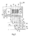
- the base units 15, 16 can be drawn along the rails 10, 12 by cabling which is now described with reference to Figs.1 and 7.
- a drive unit 60 has a housing 62 in which there is arranged a driving motor 63.
- the motor 63 has an output shaft 64 on which there is mounted co-axial first, second and third winding drums 61, 65 and 66.
- the output shaft 64 drives the winding drums via a gearbox.
- the winding drum 61 has two lengths of cable 67, 68 wound thereon in such a manner that rotation of the drum in one direction will wind on one length of cable and wind off the other length of cable.
- the cable 67 passes around a pulley 69 and extends towards the left hand of the rail 10 as viewed in Fig.1.
- Cable 67 then passes around a pulley arrangement (not shown) at the left hand end of the rail 10 and then extends back lengthwise of the rail to terminate at a pulley mounting 70 which is slidable along the rail 10.
- the pulley mounting 70 rotatably supports a pulley 72.
- An electrical cable 73 extends from a supply point 71 in the housing 62 and passes upwardly through one of the rail supports indicated at 13a. The cable then extends through an aperture in the support, passes around the pulley 72 and extends longitudinally of the rail into the base unit 15 to which the cable is attached.
- the cable, or a further cable connected thereto then extends upwardly out of the base unit 15 to supply the motor 30 with electrical power for oscillating the spray jet 20 and to supply motor 32.
- the cable 31 for supplying electricity for powering the motor for turning the rail about vertical axis 27 is electrically connected to cable 73.
- the length of cable 68 passes round a pulley 74 and extends towards the right hand end of the rail 10, the cable passing around a pulley arrangement (not shown) at the right hand end of the rail and extending alongside the rail to terminate at a pulley mounting 77 slidable along the rail 10.
- the mounting 77 rotatably supports a pulley 78.
- a water supply which may be a water main 200 or a reservoir, supplies water to a pump 79 upstream of a valve unit 76 in the housing.
- the operation of the valve unit permits detergent or other cleaning fluid or chemical to be introduced into the water.
- the detergent is contained in a suitable holder or reservoir (not shown). If desired the detergent may be introduced into the water upstream of the pump 79.
- An outlet pipe 83 extends from the valve arrangement 76 to an outlet point 84 adjacent the rail support 13a from which the electrical cable 73 extends. It will be noted that the latter rail support lies substantially mid-way between the ends of the rail 10.
- a flexible supply hose 85 extends from the outlet point 84, around the pulley 78 and into the base unit 15 to which the hose is attached. The supply hose 85 supplies an outlet 86 positioned half-way up the vertical side 18 of the arch.
- the length of the electrical cable 73 is no less than approximately half the length of the travel of the arch along the rails 10, 12 and the length of the supply hose 85 is similar.
- resilient tensioning such as a tension spring is provided in each of the cables 67, 68 to ensure that they remain taut.
- a flexible feed house 87 extends from the outlet 86 to the carriage 23 to supply liquid to the spray head 28.
- the total length of the flexible feed hose 87 is preferably no less than half the total length of travel of the carriage 23 along the rail 22. In that way, a length of the flexible feed hose 87 is kept to a minimum.
- the winding drum 65 has lengths of cable 88, 89 thereon which pass around respective pulleys 90, 92 and are then arranged in a manner identical to the cables 67, 68 around pulleys adjacent the rail 12 which terminate at pulley mountings 93, 94 slidable along rail 12.
- Outlet pipe 83 also feeds an outlet 84a identical to outlet 84 adjacent the mid-point of rail 12 and a flexible supply hose 95 identical to hose 85 is provided and supplies fluid to an outlet (not shown) identical to outlet 86 from vertical side 19.
- a feed hose (not shown) identical to feed hose 87 is provided for the carriage 25 to feed jet 28 thereon.
- An electrical cable 81 is arranged in the same way as cable 73 for supplying electric current to the motors associated with carriage 25.
- the outlet 86 may be connected to an outlet on the upper section 20 through which fluid can be supplied to a jet on the carriage 26.
- a control unit 96 may be operated by the driver of a vehicle V (Fig.2) to be cleansed and is arranged at a suitable height to align with a cab window. If desired, the height of the control unit may be adjustable.
- FIG.1 It will be noted from Fig.1 that two further rails 100, 102 are provided at ground level and a carriage 103 is movable along the rails by two lengths of cable 105, 106 from drum 66.
- the carriage 103 carries an oscillating lance 107.
- a flexible supply hose 108 is provided and an electrical supply cable 109.
- the reader is directed to our European Patent Number 0,100,680 which describes the operation of the ground level carriage 103 for cleansing the underside of a vehicle.
- the fluid feed to the carriage 103 comes from the reservoir 79 via the valve unit 76 and the electrical supply cable 109 is connected to the supply point 71 in the drive unit.
- the vehicle In use, the vehicle is driven between the rails 10, 12 so that its wheels lie on ground strips G.
- the driver of the vehicle aligns the cab window with the control unit 96.
- the control unit is associated with a control computer which has, in its memory, the cleaning sequence required for the particular vehicle being cleansed.
- the arch 14 is moved along the rails by operation of the motor 63 to the starting point for spraying a detergent mixture through the spray jets 28 and, where provided, a spray jet on carriage 26. While spraying the liquid, the carriages 23, 25 are moved upwardly and downwardly while the arch moves continuously or step wise along the rails 10, 12.
- Movement of the cables 67, 68 and 88, 89 is transmitted to the base units through the electrical cables 73, 81 when moving the arch to the left and through the hoses 85, 95 when moving the arch to the right.
- the procedure is continued until the arch has travelled the full length of the vehicle.
- the upward and downward movement of the carriages 23, 25 may be reduced by the control computer when cleaning the sides of the flat bed section and may then be arranged to travel upwardly and downwardly for greater distances when cleaning the cab section of the truck.
- the rails 22, 24 are pivoted in opposite senses about their pivotal axis (axis 37 for rail 22) so as to direct spray positively against the adjacent end of the vehicle.
- the spray heads 28 are oscillated about their axis 29.
- the travel of the arch continues until sufficient detergent mixture has been applied to the vehicle.
- the valve arrangement 76 is then computer controlled to cut off the supply of detergent mixture and to supply plain water for rinsing the vehicle.
- the arch 14 moves in reverse and the carriages 23 and 25 move vertically as before.
- the carriage 103 is moved along the rails 100, 102 under the control of the computer to clean the underside of the vehicle, the motor 63 being arranged to move the carriage 103 along its rails.
- the pump 79 is preferably capable of delivering water at the rate of between approximately 45 and 90 litres per minute. Such a pump will require considerably less power than pumps used with conventional wash arch units which need to deliver between 300 and 500 litres per minute when feeding a multiplicity of jets with cleansing fluid. Therefore, with the present invention, a pump of reduced power and energy consumption can be used whilst providing extremely high pressure jets capable of dislodging heavy soiling from vehicles.
- the unit could be used for washing other objects which could be placed beneath the arch.
Landscapes
- Engineering & Computer Science (AREA)
- Mechanical Engineering (AREA)
- Vehicle Cleaning, Maintenance, Repair, Refitting, And Outriggers (AREA)
Applications Claiming Priority (2)
| Application Number | Priority Date | Filing Date | Title |
|---|---|---|---|
| GB888815544A GB8815544D0 (en) | 1988-06-30 | 1988-06-30 | Cleaning apparatus |
| GB8815544 | 1988-06-30 |
Publications (2)
| Publication Number | Publication Date |
|---|---|
| EP0349334A2 true EP0349334A2 (fr) | 1990-01-03 |
| EP0349334A3 EP0349334A3 (fr) | 1990-11-07 |
Family
ID=10639622
Family Applications (1)
| Application Number | Title | Priority Date | Filing Date |
|---|---|---|---|
| EP19890306651 Withdrawn EP0349334A3 (fr) | 1988-06-30 | 1989-06-30 | Installation de lavage |
Country Status (2)
| Country | Link |
|---|---|
| EP (1) | EP0349334A3 (fr) |
| GB (1) | GB8815544D0 (fr) |
Cited By (6)
| Publication number | Priority date | Publication date | Assignee | Title |
|---|---|---|---|---|
| ES2057995A2 (es) * | 1991-11-28 | 1994-10-16 | Martin Antonio Ruiz | Maquina perfeccionada para lavado de camiones. |
| ES2079992A2 (es) * | 1992-02-25 | 1996-01-16 | Salinas Juan Narciso Lopez | Sistema de automatizacion del prelavado, lavado o desparafinado de vehiculos a alta presion. |
| WO2003078222A1 (fr) * | 2002-01-28 | 2003-09-25 | Leicon Ab | Unite et dispositif de traitement de vehicules et unite integree utilisee |
| US8342195B2 (en) * | 2007-03-13 | 2013-01-01 | Serge Allaire | Apparatus and method for washing a vehicle |
| CN111231905A (zh) * | 2020-04-07 | 2020-06-05 | 天津益智汽车用品有限公司 | 一种全方位自动精准洗车设备 |
| CN115214558A (zh) * | 2022-07-30 | 2022-10-21 | 三一电动车科技有限公司 | 冲洗设备及冲洗方法 |
Family Cites Families (6)
| Publication number | Priority date | Publication date | Assignee | Title |
|---|---|---|---|---|
| GB1139598A (en) * | 1966-06-17 | 1969-01-08 | Choldun Mfg Corp | Car wash installation |
| GB1296985A (fr) * | 1969-03-27 | 1972-11-22 | ||
| DE2730076A1 (de) * | 1977-07-02 | 1979-01-11 | Christ & Co O | Vorrichtung zum entwachsen von kraftfahrzeugen |
| DE3211482C2 (de) * | 1982-03-29 | 1986-08-14 | Jumbo Autowasch und Wax GmbH, 3200 Hildesheim | Fließband-Fahrzeug-Vorwaschanlage |
| DE3341650C2 (de) * | 1983-11-18 | 1985-12-12 | Mr. Wash Auto-Service AG, 4000 Düsseldorf | Reinigungssystem für Autowaschanlagen |
| FR2608114B1 (fr) * | 1986-12-16 | 1989-03-03 | Voisembert Jacques | Portique de nettoyage automatique de vehicules industriels |
-
1988
- 1988-06-30 GB GB888815544A patent/GB8815544D0/en active Pending
-
1989
- 1989-06-30 EP EP19890306651 patent/EP0349334A3/fr not_active Withdrawn
Cited By (6)
| Publication number | Priority date | Publication date | Assignee | Title |
|---|---|---|---|---|
| ES2057995A2 (es) * | 1991-11-28 | 1994-10-16 | Martin Antonio Ruiz | Maquina perfeccionada para lavado de camiones. |
| ES2079992A2 (es) * | 1992-02-25 | 1996-01-16 | Salinas Juan Narciso Lopez | Sistema de automatizacion del prelavado, lavado o desparafinado de vehiculos a alta presion. |
| WO2003078222A1 (fr) * | 2002-01-28 | 2003-09-25 | Leicon Ab | Unite et dispositif de traitement de vehicules et unite integree utilisee |
| US8342195B2 (en) * | 2007-03-13 | 2013-01-01 | Serge Allaire | Apparatus and method for washing a vehicle |
| CN111231905A (zh) * | 2020-04-07 | 2020-06-05 | 天津益智汽车用品有限公司 | 一种全方位自动精准洗车设备 |
| CN115214558A (zh) * | 2022-07-30 | 2022-10-21 | 三一电动车科技有限公司 | 冲洗设备及冲洗方法 |
Also Published As
| Publication number | Publication date |
|---|---|
| GB8815544D0 (en) | 1988-08-03 |
| EP0349334A3 (fr) | 1990-11-07 |
Similar Documents
| Publication | Publication Date | Title |
|---|---|---|
| US7806128B2 (en) | No water spill automatic steam car wash system | |
| US5016662A (en) | Rollover vehicle washing apparatus with high and low pressure spray systems | |
| EP0363579A2 (fr) | Portique de lavage de voiture roulant avec système de pulvérisation à haute et basse pression | |
| US5320121A (en) | Vehicle washing system | |
| US6325863B1 (en) | Method of washing a vehicle | |
| EP0349334A2 (fr) | Installation de lavage | |
| CN109018243A (zh) | 擦窗机及船舶 | |
| US4784166A (en) | Truck washing machine for washing trailer interiors using water under pressure as remote sole source of power, control and wash liquid | |
| US3481346A (en) | Car washing device | |
| US20040065349A1 (en) | Vehicle washing apparatus with improved control | |
| CN210749044U (zh) | 一种建筑玻璃顶保洁小车 | |
| US8342195B2 (en) | Apparatus and method for washing a vehicle | |
| CN117841916B (zh) | 固定转动轴的旋转洗车机及其控制系统 | |
| CN211252532U (zh) | 一种高铁列车清洗机 | |
| US20040035447A1 (en) | Method and apparatus for manipulating a spray bar | |
| US20080066790A1 (en) | Autonomous Personal Vehicle Washing and Drying System | |
| CN215165063U (zh) | 一种桥梁护栏自动养生装置 | |
| EP0100680A2 (fr) | Appareil de nettoyage | |
| CN205554151U (zh) | 一种汽车外表清洁停车位 | |
| CN214523711U (zh) | 移动式车身清洗装置 | |
| CN212289760U (zh) | 一种悬挂式空轨列车洗车机系统 | |
| CN224101313U (zh) | 自移动式日光温室薄膜清洗机 | |
| US3764383A (en) | Apparatus and method for washing trucks and busses | |
| CN218858370U (zh) | 一种多功能洗车机 | |
| CN221283141U (zh) | 一种光伏板水洗清洁全自动机器人 |
Legal Events
| Date | Code | Title | Description |
|---|---|---|---|
| PUAI | Public reference made under article 153(3) epc to a published international application that has entered the european phase |
Free format text: ORIGINAL CODE: 0009012 |
|
| AK | Designated contracting states |
Kind code of ref document: A2 Designated state(s): DE ES FR GB IT |
|
| PUAL | Search report despatched |
Free format text: ORIGINAL CODE: 0009013 |
|
| AK | Designated contracting states |
Kind code of ref document: A3 Designated state(s): DE ES FR GB IT |
|
| 17P | Request for examination filed |
Effective date: 19910507 |
|
| ITCL | It: translation for ep claims filed |
Representative=s name: JACOBACCI CASETTA & PERANI S.P.A. |
|
| 17Q | First examination report despatched |
Effective date: 19921214 |
|
| STAA | Information on the status of an ep patent application or granted ep patent |
Free format text: STATUS: THE APPLICATION IS DEEMED TO BE WITHDRAWN |
|
| 18D | Application deemed to be withdrawn |
Effective date: 19931221 |