EP0349521A2 - Dispositif de façonnage d'articles creux - Google Patents
Dispositif de façonnage d'articles creux Download PDFInfo
- Publication number
- EP0349521A2 EP0349521A2 EP89890123A EP89890123A EP0349521A2 EP 0349521 A2 EP0349521 A2 EP 0349521A2 EP 89890123 A EP89890123 A EP 89890123A EP 89890123 A EP89890123 A EP 89890123A EP 0349521 A2 EP0349521 A2 EP 0349521A2
- Authority
- EP
- European Patent Office
- Prior art keywords
- die
- reduced
- dies
- shaping device
- shaping
- Prior art date
- Legal status (The legal status is an assumption and is not a legal conclusion. Google has not performed a legal analysis and makes no representation as to the accuracy of the status listed.)
- Withdrawn
Links
Images
Classifications
-
- B—PERFORMING OPERATIONS; TRANSPORTING
- B21—MECHANICAL METAL-WORKING WITHOUT ESSENTIALLY REMOVING MATERIAL; PUNCHING METAL
- B21D—WORKING OR PROCESSING OF SHEET METAL OR METAL TUBES, RODS OR PROFILES WITHOUT ESSENTIALLY REMOVING MATERIAL; PUNCHING METAL
- B21D51/00—Making hollow objects
- B21D51/16—Making hollow objects characterised by the use of the objects
- B21D51/26—Making hollow objects characterised by the use of the objects cans or tins; Closing same in a permanent manner
- B21D51/2615—Edge treatment of cans or tins
- B21D51/2638—Necking
-
- B—PERFORMING OPERATIONS; TRANSPORTING
- B21—MECHANICAL METAL-WORKING WITHOUT ESSENTIALLY REMOVING MATERIAL; PUNCHING METAL
- B21D—WORKING OR PROCESSING OF SHEET METAL OR METAL TUBES, RODS OR PROFILES WITHOUT ESSENTIALLY REMOVING MATERIAL; PUNCHING METAL
- B21D41/00—Application of procedures in order to alter the diameter of tube ends
- B21D41/04—Reducing; Closing
-
- B—PERFORMING OPERATIONS; TRANSPORTING
- B21—MECHANICAL METAL-WORKING WITHOUT ESSENTIALLY REMOVING MATERIAL; PUNCHING METAL
- B21D—WORKING OR PROCESSING OF SHEET METAL OR METAL TUBES, RODS OR PROFILES WITHOUT ESSENTIALLY REMOVING MATERIAL; PUNCHING METAL
- B21D51/00—Making hollow objects
- B21D51/16—Making hollow objects characterised by the use of the objects
- B21D51/26—Making hollow objects characterised by the use of the objects cans or tins; Closing same in a permanent manner
- B21D51/2615—Edge treatment of cans or tins
-
- B—PERFORMING OPERATIONS; TRANSPORTING
- B21—MECHANICAL METAL-WORKING WITHOUT ESSENTIALLY REMOVING MATERIAL; PUNCHING METAL
- B21D—WORKING OR PROCESSING OF SHEET METAL OR METAL TUBES, RODS OR PROFILES WITHOUT ESSENTIALLY REMOVING MATERIAL; PUNCHING METAL
- B21D51/00—Making hollow objects
- B21D51/16—Making hollow objects characterised by the use of the objects
- B21D51/26—Making hollow objects characterised by the use of the objects cans or tins; Closing same in a permanent manner
- B21D51/2615—Edge treatment of cans or tins
- B21D51/2623—Curling
Definitions
- the invention relates to a shaping device for hollow bodies, in particular cans.
- Conventional monobloc cans have a seamless cylindrical body which has a conical or spherical end on its top, in which the lid with valve is inserted.
- the shape is therefore limited to the height, the diameter and the design of the end of the can.
- the can body itself is produced by extrusion and the finish is carried out by pressing in several steps. This is done in such a way that the dies are pushed from the open side of the can body over the jacket and press it in rotationally symmetrically. More recently, cylindrical, rotationally symmetrical cross-sectional reductions of the can body have been produced in this way. This made it possible to create can bodies that have the standard jumps in the diameter standard series between the normal can body and the reduced body part, which means that small lids and valves can be used.
- transition between the two cross sections lies in a plane normal to the axis of rotation of the can body.
- Another design option can be to reduce or expand the can body by beads or rollers.
- a step or transition between the reduced and non-reduced cross-section of the can is desired, which is of any shape. This is not possible with the tools used today. Because: due to a heel that is not normal to the can axis, uneven pressure is exerted on the can body and deforms it over a wide area, whereby the wall of the cans is drawn in folds.
- a tool was created for this purpose that consists of a hollow outer die, with a cylindrical interior and an inner die with a cylindrical outer surface, the inner die is arranged concentrically in the outer die and one of the two dies has a paragraph of any shape on its cylindrical wall as a transition between two Has rotary cylinders with the same axis.
- the uneven loading of the can body by the outer die is prevented, since the inner die absorbs the load.
- the can body remains straight and deformation occurs only in the area of the indentation of the heel in the die.
- the bottle body tapers towards its open side, it is particularly favorable to design the shaping device in such a way that the outer die has an arbitrarily shaped shoulder.
- a particularly inexpensive method for producing a can body for a can with a reduced upper part and arbitrarily shaped paragraph is a particularly inexpensive method for producing a can body for a can with a reduced upper part and arbitrarily shaped paragraph.
- a particularly favorable method for producing a can body for a can with a reduced upper part and any shaped paragraph between the two parts can be done so that the can is first reduced in cross-section from its open side in a known manner and then the can with the is moved open side into the forming device between the two dies, the shoulder on the outer die points towards the unreduced area of the can, the rotary cylinder diameter of the outer die approximately corresponds to the reduced or normal outer diameter of the can, the rotary cylinder diameter of the inner die corresponds approximately to the reduced inner diameter of the can and this area comes to rest on the outer wall of the inner die due to the heel and cylinder surface pressing over it, the can wall being guided through the two dies on both sides of the forming point.
- the reduced part of the can body is guided between the dies and the wall material can flow between the two dies during the pressing process and thereby receives the shape like the previously reduced part. Avoiding the can body wall is avoided.
- the rotationally symmetrical tapering of the cans has therefore proven to be advantageous as a preparatory step for this new shaping method, since all that is required is to produce any paragraph on the can body in one work step and the already reduced part as additional support for the can body to the known holder on the can base serves.
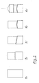
- the can is withdrawn at least once, axially rotated, moved forward again and the non-reduced can part is further deformed in each case.
- the can body After shaping the heel, the can body can be widened again in the reduced part closer to the can opening in a manner known per se and a closure pressed on.
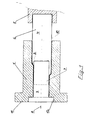
- the shaping device consists of the outer die 1, which has any paragraph 2 and the inner die 3, which consists only of a rotating cylindrical body.
- the can body 4 is clamped in the holder 5 and has an unreduced part 6, which corresponds to a standard can diameter, and a reduced part 7.
- the paragraph between the two parts 5 and 6 lies in a plane of any angle to the axis of rotation 8. Between the two dies 1 and 3 there is only so much space that the wall 10 of the can body 4 can be accommodated.
- the dies 1 and 3 are fixed to one another by means of the flanges 11 and 12 and also serve as fastening in the socket (not shown).
- the design is not limited to the drawing, but is only an example.
Landscapes
- Engineering & Computer Science (AREA)
- Mechanical Engineering (AREA)
- Shaping Metal By Deep-Drawing, Or The Like (AREA)
- Containers Having Bodies Formed In One Piece (AREA)
- Perforating, Stamping-Out Or Severing By Means Other Than Cutting (AREA)
Applications Claiming Priority (2)
| Application Number | Priority Date | Filing Date | Title |
|---|---|---|---|
| AT1694/88 | 1988-06-29 | ||
| AT169488A AT390745B (de) | 1988-06-29 | 1988-06-29 | Formgebungsgeraet fuer hohlkoerper |
Publications (2)
| Publication Number | Publication Date |
|---|---|
| EP0349521A2 true EP0349521A2 (fr) | 1990-01-03 |
| EP0349521A3 EP0349521A3 (fr) | 1991-05-08 |
Family
ID=3518974
Family Applications (1)
| Application Number | Title | Priority Date | Filing Date |
|---|---|---|---|
| EP19890890123 Withdrawn EP0349521A3 (fr) | 1988-06-29 | 1989-04-27 | Dispositif de façonnage d'articles creux |
Country Status (2)
| Country | Link |
|---|---|
| EP (1) | EP0349521A3 (fr) |
| AT (1) | AT390745B (fr) |
Cited By (2)
| Publication number | Priority date | Publication date | Assignee | Title |
|---|---|---|---|---|
| WO2009132269A3 (fr) * | 2008-04-24 | 2009-12-30 | Crown Packaging Technology, Inc. | Dispositif de striction à grande vitesse |
| US9290329B2 (en) | 2008-04-24 | 2016-03-22 | Crown Packaging Technology, Inc. | Adjustable transfer assembly for container manufacturing process |
Family Cites Families (8)
| Publication number | Priority date | Publication date | Assignee | Title |
|---|---|---|---|---|
| DE168713C (fr) * | 1902-09-20 | |||
| GB999309A (en) * | 1962-02-14 | 1965-07-21 | Rudolf Lechner | Method of and apparatus for producing seamless metal bottles |
| BE795263A (fr) * | 1972-02-11 | 1973-05-29 | K M Engineering A G | Procede de fabrication sans enlevement de copeaux de recipients en tole d'acier |
| US3948073A (en) * | 1974-09-27 | 1976-04-06 | Robert Lovell | Apparatus and method of metal forming |
| EP0020926A1 (fr) * | 1979-06-25 | 1981-01-07 | Ball Corporation | Procédé pour rétreindre des boîtes métalliques à paroi mince et boîte fabriquée d'après le procédé |
| US4392764A (en) * | 1981-09-18 | 1983-07-12 | Continental Can Company, Inc. | Necked-in container body and apparatus for and method of forming same |
| US4413497A (en) * | 1981-09-21 | 1983-11-08 | Continental Can Company, Inc. | Method of forming domed end for container |
| US4519232A (en) * | 1982-12-27 | 1985-05-28 | National Can Corporation | Method and apparatus for necking containers |
-
1988
- 1988-06-29 AT AT169488A patent/AT390745B/de not_active IP Right Cessation
-
1989
- 1989-04-27 EP EP19890890123 patent/EP0349521A3/fr not_active Withdrawn
Cited By (6)
| Publication number | Priority date | Publication date | Assignee | Title |
|---|---|---|---|---|
| WO2009132269A3 (fr) * | 2008-04-24 | 2009-12-30 | Crown Packaging Technology, Inc. | Dispositif de striction à grande vitesse |
| US8601843B2 (en) | 2008-04-24 | 2013-12-10 | Crown Packaging Technology, Inc. | High speed necking configuration |
| US9290329B2 (en) | 2008-04-24 | 2016-03-22 | Crown Packaging Technology, Inc. | Adjustable transfer assembly for container manufacturing process |
| US9308570B2 (en) | 2008-04-24 | 2016-04-12 | Crown Packaging Technology, Inc. | High speed necking configuration |
| US9968982B2 (en) | 2008-04-24 | 2018-05-15 | Crown Packaging Technology, Inc. | High speed necking configuration |
| US10751784B2 (en) | 2008-04-24 | 2020-08-25 | Crown Packaging Technology, Inc. | High speed necking configuration |
Also Published As
| Publication number | Publication date |
|---|---|
| EP0349521A3 (fr) | 1991-05-08 |
| AT390745B (de) | 1990-06-25 |
| ATA169488A (de) | 1989-12-15 |
Similar Documents
| Publication | Publication Date | Title |
|---|---|---|
| DE10040173B4 (de) | Verfahren zum Aufweiten und Verformen eines Dosenkörpers und Vorrichtung zur Durchführung des Verfahrens | |
| DE69314141T2 (de) | Herstellen von Diffusionsschweissverbindungen an superplastisch geformten Metallkonstruktionen | |
| DE2624854C3 (de) | Rollendrückvorrichtung zum Herstellen eines becherförmigen Riemenscheiben-Rohteils | |
| DE69604521T2 (de) | Herstellung eines Metallbehälters in einer Form | |
| WO2016124511A1 (fr) | Presse à poudre présentant une infrastructure conique | |
| DE3321285C2 (de) | Verfahren zum Herstellen eines Profils aus trockenem Pulvermaterial sowie Vorrichtung hierzu | |
| EP1372880A1 (fr) | Proc d pour r aliser un bord retourn | |
| DE69500280T2 (de) | Verfahren und Vorrichtung zur Herstellung eines Rands, insbesondere an einem Lampenreflektor | |
| DE69200315T3 (de) | Vorrichtung und Verfahren zum Wieder-im-Form-bringen von Behältern. | |
| DE19639677B4 (de) | Verfahren und Vorrichtung zur Herstellung des äußeren Elements eines Universalgelenks mit Kreuznuten | |
| EP0349521A2 (fr) | Dispositif de façonnage d'articles creux | |
| DE2624872A1 (de) | Verfahren zum herstellen von ungeteilten felgen | |
| EP0255719B1 (fr) | Dispositif et procédé pour fabriquer des pièces moulées creuses de forme conique ou cylindrique, en particulier tasses avec une anse | |
| EP1165272B1 (fr) | Procede de production de joints homocinetiques | |
| CH430164A (de) | Verfahren und Vorrichtung zur Herstellung von Hohlkörpern aus in einer Form aufzublasenden Kunststoffschläuchen, insbesondere zur Bildung von Kunststoffässern | |
| DE1777109A1 (de) | Verfahren und Vorrichtung zur Herstellung von Radfelgen | |
| DE2953354C2 (de) | Verfahren zum Herstellen eines inneren Gelenkkörpers für ein homokinetisches Gelenk | |
| DE2825234C2 (de) | Vorrichtung zum Herstellen gewölbter Abschlußwände | |
| DE1627681C3 (de) | Verfahren und Werkzeuge zur Herstellung einer Felge | |
| DE816780C (de) | Verfahren und Werkzeug zum Pressen von Motorkolben | |
| WO1995020474A1 (fr) | Moule de compression isostatique pour la production d'articles en forme de pots a paroi abrupte a partir de granule ceramique | |
| EP0812636A1 (fr) | Procédé et dispositif pour la fabrication de pièces à symétrie de révolution, en particulier de roues de véhicules | |
| DE2719948A1 (de) | Verfahren zur herstellung von zylindrischen druckbehaeltern | |
| EP0670207A1 (fr) | Dispositif pour la fabrication d'éléments cylindriques tubulaires | |
| DE19843165C2 (de) | Verfahren zur Herstellung einer Turbinenradschüssel für Flüssigkeitsgetriebe sowie nach dem Verfahren hergestellte Turbinenradschüssel |
Legal Events
| Date | Code | Title | Description |
|---|---|---|---|
| PUAI | Public reference made under article 153(3) epc to a published international application that has entered the european phase |
Free format text: ORIGINAL CODE: 0009012 |
|
| 17P | Request for examination filed |
Effective date: 19890510 |
|
| AK | Designated contracting states |
Kind code of ref document: A2 Designated state(s): BE CH DE ES FR GB GR IT LI LU NL SE |
|
| PUAL | Search report despatched |
Free format text: ORIGINAL CODE: 0009013 |
|
| AK | Designated contracting states |
Kind code of ref document: A3 Designated state(s): BE CH DE ES FR GB GR IT LI LU NL SE |
|
| STAA | Information on the status of an ep patent application or granted ep patent |
Free format text: STATUS: THE APPLICATION IS DEEMED TO BE WITHDRAWN |
|
| 18D | Application deemed to be withdrawn |
Effective date: 19911031 |