EP0349716A2 - Système de détection de la position de parties mobiles d'une machine - Google Patents
Système de détection de la position de parties mobiles d'une machine Download PDFInfo
- Publication number
- EP0349716A2 EP0349716A2 EP89106294A EP89106294A EP0349716A2 EP 0349716 A2 EP0349716 A2 EP 0349716A2 EP 89106294 A EP89106294 A EP 89106294A EP 89106294 A EP89106294 A EP 89106294A EP 0349716 A2 EP0349716 A2 EP 0349716A2
- Authority
- EP
- European Patent Office
- Prior art keywords
- counter
- pulses
- tachometer
- signals
- computer
- Prior art date
- Legal status (The legal status is an assumption and is not a legal conclusion. Google has not performed a legal analysis and makes no representation as to the accuracy of the status listed.)
- Granted
Links
Images

Classifications
-
- G—PHYSICS
- G01—MEASURING; TESTING
- G01D—MEASURING NOT SPECIALLY ADAPTED FOR A SPECIFIC VARIABLE; ARRANGEMENTS FOR MEASURING TWO OR MORE VARIABLES NOT COVERED IN A SINGLE OTHER SUBCLASS; TARIFF METERING APPARATUS; MEASURING OR TESTING NOT OTHERWISE PROVIDED FOR
- G01D5/00—Mechanical means for transferring the output of a sensing member; Means for converting the output of a sensing member to another variable where the form or nature of the sensing member does not constrain the means for converting; Transducers not specially adapted for a specific variable
- G01D5/12—Mechanical means for transferring the output of a sensing member; Means for converting the output of a sensing member to another variable where the form or nature of the sensing member does not constrain the means for converting; Transducers not specially adapted for a specific variable using electric or magnetic means
- G01D5/244—Mechanical means for transferring the output of a sensing member; Means for converting the output of a sensing member to another variable where the form or nature of the sensing member does not constrain the means for converting; Transducers not specially adapted for a specific variable using electric or magnetic means influencing characteristics of pulses or pulse trains; generating pulses or pulse trains
- G01D5/245—Mechanical means for transferring the output of a sensing member; Means for converting the output of a sensing member to another variable where the form or nature of the sensing member does not constrain the means for converting; Transducers not specially adapted for a specific variable using electric or magnetic means influencing characteristics of pulses or pulse trains; generating pulses or pulse trains using a variable number of pulses in a train
- G01D5/2454—Encoders incorporating incremental and absolute signals
- G01D5/2455—Encoders incorporating incremental and absolute signals with incremental and absolute tracks on the same encoder
- G01D5/2457—Incremental encoders having reference marks
Definitions
- the invention relates to a system for detecting the position of moving machine parts, in particular the rotational position of rotating parts of a printing press, an incremental encoder being provided which generates tacho pulses which are counted.
- the system according to the invention is characterized in that at least one counter circuit is arranged between the incremental encoder and a computer and has the advantage that the computer does not have to process every tacho pulse.
- a further development of the system according to the invention is that a comparator is also provided, to which the respective counter reading from the counter circuit and a default value can be fed by the computer and that an output of the comparator is connected to an input of the computer for program interruption.
- This development advantageously enables the computer to work without a program interruption after the acquisition of a predetermined position and after output of a further predetermined position until the machine has reached the further predetermined position. There is thus considerably more computing time available for the actual control and / or regulating tasks of the computer.
- further pulses are derived, the frequency of which corresponds to a predetermined multiple of the frequency of the tachometer pulses, and that the further pulses are counted instead of the tachometer pulses, or that the further pulses are fed to a further counter, the output signal of which forms low-order digits of the counter reading , while the output signals of the counter are significant digits of the Show meter reading.
- the resolution can also be increased in that the counter is incremented or decremented both by the leading edges and by the trailing edges of the tachometer pulses of two phase-shifted tachometer signals.
- the further pulses can advantageously be derived by providing a device for measuring the speed of the machine and calculating the frequency of the further pulses in the computer.
- Another further development consists in that two respectively generated by 90 ° phase-shifted clock signals, and fed via a switching network to the counter.
- the reliability of the system according to the invention is improved with respect to faults occurring in the area of the incremental encoder and the feed lines.
- the tachometer signals are linked to one another in the switching network in such a way that the tachometer pulses are only counted if there is a permissible combination of the tachometer signals.
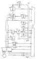
- an incremental encoder 1 known per se is provided.
- Such incremental encoders consist, for example, of a partial disk provided with optical markings, which is scanned by opto-electrical converters.
- One of the opto-electrical converters emits a pulse 0 during one revolution.
- speed signals A and B are generated that are phase-shifted and mutually meandering o to 90th
- the tachometer signals A and B each comprise 1024 pulses per revolution.
- the tachometer signals 0, A and B are fed to the inputs of a switch 2, the other inputs of which are supplied with electronically generated test signals Test-0, Test-A and Test-B.
- the changeover switch can be controlled by the computer 3, so that the circuits described below can also be tested in a test mode when the machine is at a standstill.
- the tachometer signals A and B are evaluated to record the direction of rotation and the position as well as to measure the speed or speed. To detect the direction of rotation, the tachometer signals A and B are fed to a circuit 4.
- the circuit 4 has two outputs 5, 6, a signal for identifying the direction of rotation being present at the output 5 and a pulse being emitted at the output 6 when the direction of rotation changes. While the signal indicating the direction of rotation is fed to a data input of the computer, the pulse at output 6 generates a program interruption (interrupt, IR).
- the speed is measured with two counters 8, 9, to which one of the tachometer signals A and B is fed via a changeover switch 7 and a frequency divider 17.
- the switch 7 is controlled by a circuit 18 such that if one of the tachometer signals fails, the other is forwarded.
- the frequency divider 17 is programmable, for which purpose the respective divider ratio is supplied from the computer 3 via the data bus 10.
- a counter signal is fed to the counters 8, 9, the frequency of which, according to the resolution of the speed measurement, is significantly higher than the frequency of the tachometer signals.
- the frequency of the reference signal can be varied. For this purpose, a corresponding value is fed to the oscillator 11 for the reference signal via the bus system 10.
- the speed is now measured in such a way that one of the counters alternately counts the pulses of the reference signal between two pulses emitted by the frequency divider 17.
- a program interruption IR
- the computer reads the counter reading via the data bus 10.
- the other counter has already been started, so that the duration of each period of the output signals of the frequency divider 17 is measured.
- the measured values are converted into speed values in computer 3.
- the tachometer signals A and B and the pulse 0 are fed to a counter circuit 12. It is also provided that pulse 0 triggers a program interruption.
- the counter circuit is reset by pulse 0, so that the counter reading indicates the position or the angle of rotation in relation to an initial position.
- this value is fed as an actual position to a comparator 13 and compared there with a target position which was previously written into a register 14 by the computer. If the machine has reached the target position, both values are the same and the comparator 13 triggers a program interruption, whereupon the computer initiates the measures provided for at the target position. Immediately afterwards, a new target position can be entered via register 14 can be entered. Until the machine reaches this new target position, it is not necessary to continuously record the position of the machine in the computer.
- additional pulses can be supplied to the counter circuit from an additional pulse generator 15, the frequency of which corresponds to a multiple of the frequency of the tachometer signals.
- the oscillator 15 is controlled by the computer 3 based on the frequency measurement using the circuits 7 to 11.
- the counting of the additional pulses gives the least significant digits of the actual position supplied to the comparator 13. Due to the inertia of the machine, the frequency of the tachometer signals does not change too quickly, so that the frequency measurement and thus the control of the oscillator 15 for the subsequent periods of the tachometer signal take place with sufficient accuracy.
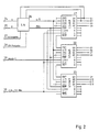
- FIG. 2 shows an exemplary embodiment for the counter circuit 12 (FIG. 1), in which three 4-bit counters of the type LS 669 are provided. Carry outputs of the counters 21 and 22 are connected to inputs of the counters 22 and 23, so that there is a total of a 12-bit counter.
- the tachometer signals A and B are fed via inputs 24, 25 to a switching network 26, where an up / down signal U / by means of a logical combination with the two least significant digits Q1 and Q2 of the counter reading.
- D and a counter enable signal ENA be derived.
- the signals DR specification and DR enable are fed to the switching network 26 via inputs 27, 28.
- the DR default signal indicates the direction of rotation of the machine.
- the DR enable signal indicates whether the speed of the machine is above or below a speed at which a change in direction can take place.
- Another input 29 is provided for pulse 0, which controls the LOAD input and thus resets the counters, since the data inputs A to D are at ground potential.
- the counter circuit 12 has an input 30 for a clock signal CLK.
- the resolution when determining the position can be increased by generating 15 additional pulses with the help of an oscillator, the frequency of which is a multiple of the frequency of the clock signals.
- the oscillator 15 generates pulses with 64 times the tacho frequency, which are fed to a further counter 31 of the type LS 669.
- the counting direction of the further counter 31 is controlled by the DR preset signal. This increases the counter reading to 16 digits (Q1 'to Q4', Q1 to Q12) and increases the resolution to 16 times, since a fourfold counting frequency is already achieved by evaluating both edges of the tachometer signals A and B.
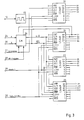
- the switching network comprises an antivalence circuit 41 and two equivalence circuits 42, 43.
- the tachometer signals A, B are fed via inputs 24, 25 to both inputs of the antivalence circuit 41.
- the output of the antivalence circuit 41 is connected to an input of the equivalence circuit 43, at the other input of which the least significant bit (LSB) Q1 is present.
- the release signal can be output 44 ENA for the counter.
- To obtain an up / down signal U / D the tacho signal A and the second least significant digit Q2 of the counter reading are fed to the equivalence circuit 42, at the output 45 of which the signal U / D can be removed.
- FIG. 5 shows time diagrams of the signals O, A and B for a predetermined direction of rotation, for example for clockwise rotation.
- values of Q1 and Q2 of the counter 21 and the total count Q1 to Q12 are indicated in FIG.
- the counter reading Q1 'to Q4' (Fig. 3) is indicated
- the signal 0 occurs once during each revolution, while the tachometer signals A and B occur more frequently according to the division of the incremental encoder - for example 1024 times per revolution.
- the tachometer signals A and B are out of phase with each other by 90 o .
- the counter is reset by pulse 0, so that the counter reading becomes 0 and the two least significant digits Q1 and Q2 also assume the value 0.
- a and B become different sizes, so that the value 1 is at the output of the antivalence circuit 41.
- the switching network 26 including the two least significant digits of the counter 21, can then assume the states Z0, Z1, Z2 and Z3.
- the values present at the outputs Q1 and Q2 in these states are indicated in the circles representing the states.
- a transition from one state to another can only take place in the sense of counting up or down, which is indicated in FIG. 6 by arrows between the circles.
- the filtering effect of the switching network is explained using the example of an interference pulse 46 (FIG. 5).
- the switching network shown in FIG. 4 thus has the effect that only the respectively neighboring states are permitted in any state. Counter reading 0 can therefore only be followed by counter reading 1 or 4095.
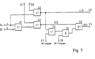
- Another Increasing operational reliability is achieved by specifying the direction of rotation via the computer 3 (FIG. 1). A change in the direction of rotation indicated by the tachometer signals A and B is recognized as an error if this contradicts the signal DR specification supplied by the computer. However, this additional check can lead to errors at standstill or at low speeds and is therefore switched off if a change of direction is possible due to low speeds. A further DR release signal is therefore supplied by the computer, which assumes the value 1 above a predetermined speed.
- the switching network according to FIG. 7 contains an antivalence circuit 50, an AND circuit 51 and an OR circuit 52.
- this counter can only be blocked if the value 1 is supplied to both inputs of the AND circuit 51. This is the case when both the DR enable signal has the value 1 and the two signals U / which are obtained independently of one another and which characterize the direction of rotation. D and DR specification are different from each other.
Landscapes
- Physics & Mathematics (AREA)
- General Physics & Mathematics (AREA)
- Transmission And Conversion Of Sensor Element Output (AREA)
- Length Measuring Devices With Unspecified Measuring Means (AREA)
- Optical Transform (AREA)
- Inking, Control Or Cleaning Of Printing Machines (AREA)
- Control Of Position Or Direction (AREA)
Applications Claiming Priority (2)
| Application Number | Priority Date | Filing Date | Title |
|---|---|---|---|
| DE3815534A DE3815534A1 (de) | 1988-05-06 | 1988-05-06 | System zur erfassung der position von beweglichen maschinenteilen |
| DE3815534 | 1988-05-06 |
Publications (3)
| Publication Number | Publication Date |
|---|---|
| EP0349716A2 true EP0349716A2 (fr) | 1990-01-10 |
| EP0349716A3 EP0349716A3 (fr) | 1991-03-06 |
| EP0349716B1 EP0349716B1 (fr) | 1993-02-10 |
Family
ID=6353836
Family Applications (1)
| Application Number | Title | Priority Date | Filing Date |
|---|---|---|---|
| EP89106294A Expired - Lifetime EP0349716B1 (fr) | 1988-05-06 | 1989-04-10 | Système de détection de la position de parties mobiles d'une machine |
Country Status (6)
| Country | Link |
|---|---|
| US (1) | US5058145A (fr) |
| EP (1) | EP0349716B1 (fr) |
| JP (1) | JPH01320424A (fr) |
| AU (1) | AU618800B2 (fr) |
| CA (1) | CA1335828C (fr) |
| DE (2) | DE3815534A1 (fr) |
Families Citing this family (20)
| Publication number | Priority date | Publication date | Assignee | Title |
|---|---|---|---|---|
| DE3815530A1 (de) * | 1988-05-06 | 1989-11-16 | Heidelberger Druckmasch Ag | Verfahren zur ermittlung der drehzahl einer maschine |
| DE3815533C1 (fr) * | 1988-05-06 | 1989-11-30 | Heidelberger Druckmaschinen Ag, 6900 Heidelberg, De | |
| JPH04125408A (ja) * | 1990-09-17 | 1992-04-24 | Futaba Corp | リニアスケール測長装置 |
| US5170416A (en) * | 1991-06-17 | 1992-12-08 | Tektronix, Inc. | Encoder duty-cycle error correction |
| JP2720642B2 (ja) * | 1991-07-30 | 1998-03-04 | 三菱電機株式会社 | 多回転絶対値エンコーダ |
| DE4244278C1 (de) * | 1992-12-28 | 1994-03-17 | Heidelberger Druckmasch Ag | Schaltungsanordnung zum Detektieren von im Mehrfarbendruck erzeugten Registermarken |
| SE500979C2 (sv) * | 1993-02-22 | 1994-10-10 | Leine & Linde Ab | Givarenhet för indikering av ett kodorgans läge relativt ett detektororgan |
| JP3367260B2 (ja) * | 1995-03-24 | 2003-01-14 | 三菱電機株式会社 | エンコーダ装置及びサーボモーター制御装置 |
| DE19520919C2 (de) * | 1995-06-08 | 1998-02-26 | Roland Man Druckmasch | Steuerung für eine Druckmaschine |
| DE19520918C2 (de) * | 1995-06-08 | 1998-02-26 | Roland Man Druckmasch | Steuerung für eine Druckmaschine |
| US6246343B1 (en) * | 1999-03-05 | 2001-06-12 | Ford Global Technologies, Inc. | Increment encoder failure detection |
| IL136016A (en) * | 2000-05-08 | 2005-11-20 | Yaskawa Eshed Technology Ltd | High sensor resolution position sensor device and method |
| DE10117194B4 (de) | 2001-04-05 | 2013-09-19 | Anton Rodi | Winkel- oder Wegmessgeber |
| DE10203020A1 (de) * | 2002-01-26 | 2003-07-31 | Roland Man Druckmasch | Vorrichtung zur eindeutigen Lagebestimmung in einem Antriebssystem mit beliebiger Übersetzung |
| DE102004007069A1 (de) * | 2004-02-13 | 2005-08-25 | Goss International Montataire S.A. | Rotationselement einer Druckmaschine, mit einem Encoder |
| EP1580561A1 (fr) * | 2004-03-24 | 2005-09-28 | Alcatel | Procede et dispositif pour la détermination de la direction de mouvement avec tolérance aux erreurs |
| US7231262B2 (en) * | 2004-07-30 | 2007-06-12 | Enterprise Management Services, L.L.C. | Apparatus for monitoring and controlling use of equipment |
| US7178412B2 (en) * | 2004-07-30 | 2007-02-20 | Ballard Power Systems Corporation | Encoder failure detection |
| ES2310090B1 (es) * | 2006-05-26 | 2009-11-05 | Fagor, S. Coop. | Dispositivo optoelectronico de medida. |
| US7460030B2 (en) * | 2006-12-05 | 2008-12-02 | Continental Automotive Systems Us, Inc. | System and method for encoder failure detection |
Family Cites Families (25)
| Publication number | Priority date | Publication date | Assignee | Title |
|---|---|---|---|---|
| DE1978007U (de) * | 1962-08-24 | 1968-02-01 | Continental Elektro Ind Ag | Digitale winkel- oder stellungsmessvorrichtung. |
| GB1470383A (en) * | 1973-04-03 | 1977-04-14 | Lucas Electrical Ltd | Apparatus for producing signals indicating increments of angular movement of a body |
| DD125296A1 (fr) * | 1976-01-29 | 1977-04-13 | ||
| US4129862A (en) * | 1976-03-10 | 1978-12-12 | Lincoln D | Apparatus for digitally encoding the angular position of a shaft with respect to a reference bearing |
| DE2656304C3 (de) * | 1976-12-11 | 1980-02-14 | Dr. Johannes Heidenhain Gmbh, 8225 Traunreut | Elektronische Schaltung |
| IT1085960B (it) * | 1977-08-04 | 1985-05-28 | Alfa Romeo Spa | Dispositivo per il rilevamento della posizione di un organo mobile |
| US4135082A (en) * | 1977-09-13 | 1979-01-16 | E. I. Du Pont De Nemours And Company | Electrical pulse train comparator |
| US4171522A (en) * | 1978-03-22 | 1979-10-16 | Real Time Systems, Inc. | Electronic angular position encoder apparatus |
| JPS5585217A (en) * | 1978-09-29 | 1980-06-27 | Hitachi Ltd | Detecting device for rotation angle of engine |
| DE2930793A1 (de) * | 1979-07-28 | 1981-02-12 | Licentia Gmbh | Schaltungsanordnung zur erzeugung von signalen fuer die wegmessung oder positionsbestimmung mit einem impulsgeber |
| GB2065399A (en) * | 1979-12-10 | 1981-06-24 | Sigma Ltd | Determining a dimensional parameter of a workpiece |
| US4308500A (en) * | 1979-12-14 | 1981-12-29 | Rca Corporation | Incremental encoder for measuring positions of objects such as rotating shafts |
| DD150028A1 (de) * | 1980-04-10 | 1981-08-12 | Max Janicki | Einrichtung zur steuerung und ueberwachung von stellgliedern an druckmaschinen |
| US4475163A (en) * | 1980-11-03 | 1984-10-02 | Continental Emsco | System for calculating and displaying cable payout from a rotatable drum storage device |
| EP0070305A4 (fr) * | 1981-01-21 | 1983-08-09 | Alpha Electronics | Appareil de mesure d'un deplacement angulaire. |
| US4442532A (en) * | 1981-05-19 | 1984-04-10 | Matsushita Electric Industrial Co., Ltd. | Encoder output pulse detection using two stage shift register and clock oscillator |
| US4475086A (en) * | 1982-03-31 | 1984-10-02 | Eastman Kodak Company | Duty cycle detector |
| DE3219894C2 (de) * | 1982-05-27 | 1984-08-30 | Danfoss A/S, Nordborg | Inkremental-Digital-Umsetzer |
| DE3318351C2 (de) * | 1983-05-20 | 1986-05-22 | Preh, Elektrofeinmechanische Werke Jakob Preh Nachf. Gmbh & Co, 8740 Bad Neustadt | Schaltungsanordnung für eine drehzahl- und drehrichtungsabhängige Auswerteschaltung eines inkrementalen Drehrichtungsimpulsgebers |
| JPS61287320A (ja) * | 1985-06-13 | 1986-12-17 | Matsushita Electric Ind Co Ltd | 座標位置の位置決めカウンタ装置 |
| US4714913A (en) * | 1985-07-16 | 1987-12-22 | Cohen Robert K | Quadrature phase signal processor |
| IT1201346B (it) * | 1985-08-23 | 1989-01-27 | Roberto Chiavaccini | Dispositivo per la misura di spostamenti angolari di un elemento mobile rispetto a uno fisso,particolarmente per bilance ad inclinazione e metodo per effettuare tale misura |
| JPS62162968A (ja) * | 1986-01-13 | 1987-07-18 | Hitachi Ltd | 速度検出装置 |
| US4881248A (en) * | 1986-08-28 | 1989-11-14 | Nec Corporation | Counter circuit provided with means for reading out counted data by read-command signal applied asynchronously with clock signals to be counted |
| DE3815533C1 (fr) * | 1988-05-06 | 1989-11-30 | Heidelberger Druckmaschinen Ag, 6900 Heidelberg, De |
-
1988
- 1988-05-06 DE DE3815534A patent/DE3815534A1/de active Granted
-
1989
- 1989-03-28 CA CA000594890A patent/CA1335828C/fr not_active Expired - Fee Related
- 1989-04-10 DE DE8989106294T patent/DE58903503D1/de not_active Expired - Fee Related
- 1989-04-10 EP EP89106294A patent/EP0349716B1/fr not_active Expired - Lifetime
- 1989-04-27 AU AU33761/89A patent/AU618800B2/en not_active Ceased
- 1989-05-02 JP JP1112288A patent/JPH01320424A/ja active Pending
- 1989-05-08 US US07/348,986 patent/US5058145A/en not_active Expired - Fee Related
Also Published As
| Publication number | Publication date |
|---|---|
| US5058145A (en) | 1991-10-15 |
| DE3815534C2 (fr) | 1992-10-01 |
| DE58903503D1 (de) | 1993-03-25 |
| EP0349716A3 (fr) | 1991-03-06 |
| EP0349716B1 (fr) | 1993-02-10 |
| AU618800B2 (en) | 1992-01-09 |
| CA1335828C (fr) | 1995-06-06 |
| DE3815534A1 (de) | 1989-11-16 |
| AU3376189A (en) | 1989-11-09 |
| JPH01320424A (ja) | 1989-12-26 |
Similar Documents
| Publication | Publication Date | Title |
|---|---|---|
| DE3815534C2 (fr) | ||
| DE2851853C2 (de) | Verfahren und Vorrichtung zur Erfassung der Winkellage eines sich drehenden Teils | |
| DE4006683C2 (de) | Vorrichtung zum Herabsetzen des Energieverbrauchs in einem Lenkwinkelerfassungssystem | |
| DE3831520C2 (de) | System zur Verarbeitung von Signalen von einem Winkelpositionsumformer | |
| DE2553806B2 (de) | Schaltungsanordnung zur digitalen Messung der Periodendauer einer Wechselspannung | |
| DE2724696C3 (de) | Verfahren zur Bestimmung des Unwuchtwinkels und Vorrichtung hierzu | |
| EP0340481B1 (fr) | Arrangement pour dépouiller les signaux d'un capteur incrémenteil | |
| DE102011083042A1 (de) | Überwachungseinheit und Verfahren zur Überwachung von Positionssignalen inkrementaler Positionsmesseinrichtungen | |
| EP0087025A2 (fr) | Procédé et dispositif pour mesurer avec grande précision la position de phase et le déphasage de deux séries d'impulsions | |
| DE3542908C2 (fr) | ||
| DE4339303A1 (de) | Phasenmeßvorrichtung | |
| DE3709395C2 (fr) | ||
| DE3815530C2 (fr) | ||
| DE2344819C2 (de) | Einrichtung zur Registerregelung von Druckwerken von Rotationsdruckmaschinen | |
| EP0343352A1 (fr) | Procédé et dispositif de mesure de la vitesse de rotation d'une machine | |
| EP0062698A2 (fr) | Circuit d'évaluation pour un transducteur de vitesse de rotation | |
| EP0728260B1 (fr) | Circuit de comptage electronique | |
| DE2829292C2 (de) | Vorrichtung zum Messen des Drehwinkels einer rotierenden Welle | |
| DE3336976C2 (fr) | ||
| DE3025379A1 (de) | Vorrichtung zur ueberwachung des ausgangssignals eines drehgebers | |
| DE3733136A1 (de) | Elektrische anordnung zur messung der drehgeschwindigkeit | |
| DE4403218C2 (de) | Drehgeber | |
| DE2621179A1 (de) | Verfahren zur erfassung der drehrichtung rotierender teile | |
| DE3714901A1 (de) | Zeitmessvorrichtung | |
| DE2949542C2 (de) | Verfahren und Vorrichtung zum Eindrehen eines auszuwuchtenden Rotors, dessen Art bzw. äußere Form einen Massenausgleich nur an bestimmten vorgegebenen Ausgleichsstellen in Komponenten ermöglicht |
Legal Events
| Date | Code | Title | Description |
|---|---|---|---|
| PUAI | Public reference made under article 153(3) epc to a published international application that has entered the european phase |
Free format text: ORIGINAL CODE: 0009012 |
|
| 17P | Request for examination filed |
Effective date: 19890410 |
|
| AK | Designated contracting states |
Kind code of ref document: A2 Designated state(s): CH DE FR GB IT LI SE |
|
| PUAL | Search report despatched |
Free format text: ORIGINAL CODE: 0009013 |
|
| AK | Designated contracting states |
Kind code of ref document: A3 Designated state(s): CH DE FR GB IT LI SE |
|
| 17Q | First examination report despatched |
Effective date: 19920305 |
|
| GRAA | (expected) grant |
Free format text: ORIGINAL CODE: 0009210 |
|
| AK | Designated contracting states |
Kind code of ref document: B1 Designated state(s): CH DE FR GB IT LI SE |
|
| PG25 | Lapsed in a contracting state [announced via postgrant information from national office to epo] |
Ref country code: SE Effective date: 19930210 |
|
| REF | Corresponds to: |
Ref document number: 58903503 Country of ref document: DE Date of ref document: 19930325 |
|
| ITF | It: translation for a ep patent filed | ||
| ET | Fr: translation filed | ||
| GBT | Gb: translation of ep patent filed (gb section 77(6)(a)/1977) |
Effective date: 19930517 |
|
| PLBE | No opposition filed within time limit |
Free format text: ORIGINAL CODE: 0009261 |
|
| STAA | Information on the status of an ep patent application or granted ep patent |
Free format text: STATUS: NO OPPOSITION FILED WITHIN TIME LIMIT |
|
| 26N | No opposition filed | ||
| PGFP | Annual fee paid to national office [announced via postgrant information from national office to epo] |
Ref country code: CH Payment date: 19950526 Year of fee payment: 7 |
|
| PGFP | Annual fee paid to national office [announced via postgrant information from national office to epo] |
Ref country code: GB Payment date: 19960325 Year of fee payment: 8 |
|
| PGFP | Annual fee paid to national office [announced via postgrant information from national office to epo] |
Ref country code: FR Payment date: 19960402 Year of fee payment: 8 |
|
| PG25 | Lapsed in a contracting state [announced via postgrant information from national office to epo] |
Ref country code: LI Effective date: 19960430 Ref country code: CH Effective date: 19960430 |
|
| REG | Reference to a national code |
Ref country code: CH Ref legal event code: PL |
|
| PG25 | Lapsed in a contracting state [announced via postgrant information from national office to epo] |
Ref country code: GB Effective date: 19970410 |
|
| GBPC | Gb: european patent ceased through non-payment of renewal fee |
Effective date: 19970410 |
|
| PG25 | Lapsed in a contracting state [announced via postgrant information from national office to epo] |
Ref country code: FR Free format text: LAPSE BECAUSE OF NON-PAYMENT OF DUE FEES Effective date: 19971231 |
|
| REG | Reference to a national code |
Ref country code: FR Ref legal event code: ST |
|
| PGFP | Annual fee paid to national office [announced via postgrant information from national office to epo] |
Ref country code: DE Payment date: 19991230 Year of fee payment: 12 |
|
| PG25 | Lapsed in a contracting state [announced via postgrant information from national office to epo] |
Ref country code: DE Free format text: LAPSE BECAUSE OF NON-PAYMENT OF DUE FEES Effective date: 20020201 |
|
| PG25 | Lapsed in a contracting state [announced via postgrant information from national office to epo] |
Ref country code: IT Free format text: LAPSE BECAUSE OF NON-PAYMENT OF DUE FEES;WARNING: LAPSES OF ITALIAN PATENTS WITH EFFECTIVE DATE BEFORE 2007 MAY HAVE OCCURRED AT ANY TIME BEFORE 2007. THE CORRECT EFFECTIVE DATE MAY BE DIFFERENT FROM THE ONE RECORDED. Effective date: 20050410 |