EP0349738A2 - Cylindre de fermeture - Google Patents
Cylindre de fermeture Download PDFInfo
- Publication number
- EP0349738A2 EP0349738A2 EP89108681A EP89108681A EP0349738A2 EP 0349738 A2 EP0349738 A2 EP 0349738A2 EP 89108681 A EP89108681 A EP 89108681A EP 89108681 A EP89108681 A EP 89108681A EP 0349738 A2 EP0349738 A2 EP 0349738A2
- Authority
- EP
- European Patent Office
- Prior art keywords
- coupling part
- key
- cylinder core
- cylinder according
- tumblers
- Prior art date
- Legal status (The legal status is an assumption and is not a legal conclusion. Google has not performed a legal analysis and makes no representation as to the accuracy of the status listed.)
- Granted
Links
Images
Classifications
-
- E—FIXED CONSTRUCTIONS
- E05—LOCKS; KEYS; WINDOW OR DOOR FITTINGS; SAFES
- E05B—LOCKS; ACCESSORIES THEREFOR; HANDCUFFS
- E05B17/00—Accessories in connection with locks
- E05B17/04—Devices for coupling the turning cylinder of a single or a double cylinder lock with the bolt operating member
-
- E—FIXED CONSTRUCTIONS
- E05—LOCKS; KEYS; WINDOW OR DOOR FITTINGS; SAFES
- E05B—LOCKS; ACCESSORIES THEREFOR; HANDCUFFS
- E05B29/00—Cylinder locks and other locks with plate tumblers which are set by pushing the key in
- E05B29/0026—Cylinder locks and other locks with plate tumblers which are set by pushing the key in with longitudinally movable cylinder
Definitions
- the invention relates to a locking cylinder with a cylinder core rotatably mounted in a cylinder housing, in which tumblers are mounted which extend into a key channel.
- the object of the invention is to improve a lock of the type mentioned in such a way that a violent displacement of the cylinder core into the lock does not lead to engagement.
- a plate-shaped or cylindrical coupling part is mounted axially parallel to the side of the key channel and is movable in the axial direction, that the coupling part is in a first position when the key is removed, in which at least one tumbler is in the path of movement of the coupling part and a displacement of the coupling part prevents the tumblers from being moved into a position releasing the coupling part and the cylinder core by inserting the key and from being displaceable into a second position by the key of the coupling part, in which the coupling part connects the cylinder core to an important part, in particular coupled to the locking bolt or a transmission part.
- a part connected to the coupling part in particular a projection of the coupling part, extends into the key channel for displacing the coupling part.
- the part connected to the coupling part can be a spring element, in particular a leaf spring, which can be actuated by the tip or a projection of the key. This ensures that a tool inserted into the key channel cannot move the coupling part even when high force is used.
- the spring form a toggle mechanism.
- a particularly safe function is achieved when the spring is plate-shaped and in particular in two parts or consists of two plate springs.
- the coupling part forms a projection which, in the second position of the coupling part, abuts the important part when the cylinder core is rotated. Also, in the first position, the coupling part should not protrude beyond the rear end of the cylinder core, so that when the cylinder core is forcibly shifted, coupling cannot occur.
- tongue-shaped projections are formed on the tumblers, which engage in recesses in the coupling part and lock the coupling part when the key is removed.
- an element in particular a plate, is slidably mounted in the cylinder housing, which extends into the key channel and can be moved outwards against spring pressure by the key shaft and only after reaching a certain area of the key shaft with full insertion of the key allows turning the key.
- an element in particular a plate, in particular a hardened plate, is fastened transversely to the direction of key insertion and extends into the key channel in such a way that turning the key is only possible after the key has been fully inserted.
- a particularly simple and reliable construction is achieved when the coupling part is hollow cylindrical or cylindrical and coaxially surrounds the cylinder core.
- a support for the movement of the coupling part is generated when the coupling part lies against the respective tumbler via an inclined surface and when the key is removed, the inclined surface acts on the coupling part in the direction of movement towards the first position.
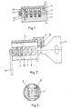
- a lock cylinder has a cylinder core 1 which is mounted in a cylinder housing 2.
- the cylinder core has a coaxial key channel 3 approximately in the middle, to which a plurality of plate-like tumblers 4 are mounted at right angles.
- the tumblers 4 protrude beyond the outer dimensions of the cylinder core into recesses in the cylinder housing 2, so that the cylinder core 1 is prevented from rotating.
- a coupling part 6, 6a is longitudinally displaceably mounted, the longitudinal axis of which is parallel to the axis of rotation of the cylinder core 1 and can thus be displaced in its longitudinal direction parallel to the cylinder core axis.
- the coupling part 6, 6a rests with its inner side surface on the side edges of the tumblers 4, tongue-shaped projections 7 being freely movable in transverse slots 8 of the coupling part 6, 6a, as long as the coupling part is pulled out when the key 5 is removed in its first position (basic position).
- each tumbler 4 can move freely and protrude beyond the cylinder core 1 in order to lock it in the direction of rotation.
- each tumbler 4 has a nose 9 protruding on the other longitudinal edge of the tumbler, which is loaded by a helical compression spring in order to move the tumbler into the locking position when the key is not inserted.
- the tumblers 4 are moved so far into the cylinder core 1 that they no longer protrude beyond the outer jacket of the cylinder core, so that the cylinder core can be rotated.
- all the projections 7 are located at the level of a longitudinal recess 10 in the coupling part 6, 6a which connects the transverse slots 8 to one another.
- the coupling part 6, 6a is held in its first position according to FIG.
- the coupling part 6, 6a can be moved in the key insertion direction.
- This movement is generated by the key itself via a leaf spring 11 which is mounted transversely to the cylinder core 1 in the inner end of the key channel and against which the key tip abuts.
- the leaf spring 11 is fastened with the end used in the coupling part 6, 6a in the cylinder core 1 and the remaining area is movable in a corresponding recess 12 in the cylinder core 1.
- the other end of the leaf spring 11 lies in a groove 13 of the coupling part 6, 6a, so that a movement of the leaf spring 11 in the key insertion direction generates a movement of the coupling part 6, 6a in the same direction.
- a nose 14 formed on the coupling part 6, 6a is moved out of the cylinder core 1 on the side opposite the key insertion side in order to enter the range of movement of an important part, in particular a locking bolt or, as in this case, an actuating lever 15 which, when the cylinder core 1 is rotated is also rotated by the nose 14 in order to move an important part, in particular a locking bolt, directly or via further transmission parts.
- an actuating lever 15 which, when the cylinder core 1 is rotated is also rotated by the nose 14 in order to move an important part, in particular a locking bolt, directly or via further transmission parts.
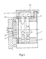
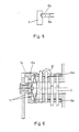
- the interaction between the tumblers 4 and the coupling part 6, 6a can be reversed kenematically, i. H. the coupling part 6, 6a can have projections which extend into recesses in the tumblers 4, as shown in FIG. 4. Furthermore, inclined surfaces can be provided between the coupling part and the tumblers, as shown in FIG. 5, in order to provide movement support for the plate-shaped coupling part 6, 6a when the key is pulled out by the tumbler plates.
- the spring can form a toggle mechanism or be part of a toggle mechanism so that during the insertion of the key the coupling part 6, 6a is not yet moved by the spring, but shortly before or after fully inserting the Key snapped the spring according to Figure 6 and the coupling part 6, 6a moved suddenly into extended position.
- the spring can be plate-shaped and in particular divided into two.
- a further additional or alternative securing for a complete insertion of the key and a complete removal of the coupling part 6, 6a can be given by the fact that in the cylinder housing 2 a plate 16 is arranged transversely to the cylinder axis, which is radially displaceable and one at the end facing the key shaft Has recess that is form-fitting with the profile of the key shaft, as long as the
- the coupling part 6, 6a does not necessarily have to be plate-shaped or profile-shaped, but it can also be formed by a hollow cylinder 6a or a hollow cylinder segment, as shown in FIG. 6.
- This hollow cylinder 6a or this segment is preferably arranged coaxially to the axis of rotation of the cylinder core 1 and is in particular mounted on the outside of the cylinder core 1 surrounding it and thus lies between the cylinder core 1 and the cylinder housing 2.
- This coupling part 6a also has a projection according to the embodiment according to FIG or a nose 14, which reaches the area of the lever 15. Instead of a nose 14, however, a differently shaped projection or a plurality of projections can also be provided, in particular conventional coupling means such as coupling teeth
Landscapes
- Physics & Mathematics (AREA)
- Electromagnetism (AREA)
- Lock And Its Accessories (AREA)
Applications Claiming Priority (2)
| Application Number | Priority Date | Filing Date | Title |
|---|---|---|---|
| DE3822975 | 1988-07-07 | ||
| DE19883822975 DE3822975C2 (de) | 1988-07-07 | 1988-07-07 | Schließzylinder |
Publications (3)
| Publication Number | Publication Date |
|---|---|
| EP0349738A2 true EP0349738A2 (fr) | 1990-01-10 |
| EP0349738A3 EP0349738A3 (fr) | 1991-05-08 |
| EP0349738B1 EP0349738B1 (fr) | 1993-12-01 |
Family
ID=6358136
Family Applications (1)
| Application Number | Title | Priority Date | Filing Date |
|---|---|---|---|
| EP19890108681 Expired - Lifetime EP0349738B1 (fr) | 1988-07-07 | 1989-05-13 | Cylindre de fermeture |
Country Status (3)
| Country | Link |
|---|---|
| EP (1) | EP0349738B1 (fr) |
| DE (1) | DE3822975C2 (fr) |
| ES (1) | ES2048783T3 (fr) |
Cited By (4)
| Publication number | Priority date | Publication date | Assignee | Title |
|---|---|---|---|---|
| EP0401853A3 (fr) * | 1989-06-09 | 1991-12-11 | SCHÜRING GMBH & CO. FENSTERTECHNOLOGIE KG | Dispositif de fermeture |
| GB2347714A (en) * | 1999-03-10 | 2000-09-13 | Rover Group | Plate tumbler barrel lock |
| WO2012059094A1 (fr) * | 2010-10-08 | 2012-05-10 | Huf Hülsbeck & Fürst Gmbh & Co. Kg | Cylindre de serrure |
| CN106917545A (zh) * | 2017-04-25 | 2017-07-04 | 珠海优特电力科技股份有限公司 | 锁芯组件及解锁装置 |
Families Citing this family (1)
| Publication number | Priority date | Publication date | Assignee | Title |
|---|---|---|---|---|
| DE19700333A1 (de) * | 1997-01-08 | 1998-07-09 | Danijel Golub | Umstellbares Zylinderschloß auf Standard oder Not- und Gefahrenfunktion mit Zutrittsberechtigungsfreigabe ohne Ausbau und durch unterschiedlich gebildete Schlüssel auf die Kupplungsmechanik wirkend bestimmbar |
Family Cites Families (5)
| Publication number | Priority date | Publication date | Assignee | Title |
|---|---|---|---|---|
| DE2351975A1 (de) * | 1972-10-20 | 1974-04-25 | Neiman & Co Kg | Druckknopfartig betaetigbares drehzylinderschloss |
| AT367147B (de) * | 1980-01-14 | 1982-06-11 | Evva Werke | Zylinderschloss mit flachschluessel, insbesondere auf permanentmagnetbasis |
| FR2579655B2 (fr) * | 1984-10-12 | 1988-03-25 | Antivols Simplex Sa | Verrou a cle plate a pistons anti-effraction |
| FR2571772B1 (fr) * | 1984-10-12 | 1988-01-29 | Antivols Simplex Sa | Verrou a cle plate a pistons anti-effraction |
| FR2592423B1 (fr) * | 1985-12-27 | 1988-04-08 | Peugeot | Serrure de surete a cle, notamment pour vehicule automobiles |
-
1988
- 1988-07-07 DE DE19883822975 patent/DE3822975C2/de not_active Expired - Fee Related
-
1989
- 1989-05-13 ES ES89108681T patent/ES2048783T3/es not_active Expired - Lifetime
- 1989-05-13 EP EP19890108681 patent/EP0349738B1/fr not_active Expired - Lifetime
Cited By (5)
| Publication number | Priority date | Publication date | Assignee | Title |
|---|---|---|---|---|
| EP0401853A3 (fr) * | 1989-06-09 | 1991-12-11 | SCHÜRING GMBH & CO. FENSTERTECHNOLOGIE KG | Dispositif de fermeture |
| GB2347714A (en) * | 1999-03-10 | 2000-09-13 | Rover Group | Plate tumbler barrel lock |
| WO2012059094A1 (fr) * | 2010-10-08 | 2012-05-10 | Huf Hülsbeck & Fürst Gmbh & Co. Kg | Cylindre de serrure |
| CN106917545A (zh) * | 2017-04-25 | 2017-07-04 | 珠海优特电力科技股份有限公司 | 锁芯组件及解锁装置 |
| CN106917545B (zh) * | 2017-04-25 | 2022-03-22 | 珠海优特电力科技股份有限公司 | 锁芯组件及解锁装置 |
Also Published As
| Publication number | Publication date |
|---|---|
| EP0349738A3 (fr) | 1991-05-08 |
| EP0349738B1 (fr) | 1993-12-01 |
| ES2048783T3 (es) | 1994-04-01 |
| DE3822975A1 (de) | 1990-01-11 |
| DE3822975C2 (de) | 1997-07-31 |
Similar Documents
| Publication | Publication Date | Title |
|---|---|---|
| AT392818B (de) | Schliesssystem | |
| DE69111409T2 (de) | Zylinderschlösser, mit auswechselbaren Zylindern. | |
| DE102011015314B4 (de) | Schließzylinder mit Zuhaltungsscheiben und Sperrstift, sowie Kombination aus einem solchen Schließzylinder und einem Schlüssel | |
| EP0472495A1 (fr) | Clé et cylindre pour serrure de sécurité | |
| DE2942789A1 (de) | Permutationsschloss | |
| DE69904408T2 (de) | Schlüssel mit bewegbarem stift, sicherheitsdrehzylinder und damit ausgerüstetes schloss | |
| DE602005004778T2 (de) | Geteilte spindel | |
| EP0252314A2 (fr) | Serrure de direction à blocage du mouvement de rotation de la colonne de direction d'un véhicule automobile | |
| DE102009008922A1 (de) | Kupplungseinrichtung für einen zwei Zylinderkerne beinhaltenden Doppelschließzylinder mit Not- und Gefahrenfunktion | |
| EP0349738B1 (fr) | Cylindre de fermeture | |
| DE3338713C2 (de) | Schließzylinder | |
| CH650054A5 (de) | Notschluesseleinrichtung an einem doppelzylinderschloss. | |
| EP2166179A1 (fr) | Serrure cylindrique, notamment pour un verrou de porte | |
| DE29514514U1 (de) | Zylinderschloß mit Zylinderkern und Zylindergehäuse | |
| DE19959833C1 (de) | Schließvorrichtung für insbesondere an Fahrzeugen vollziehbare Schließfunktionen | |
| DE19544840A1 (de) | Zylinderschloß mit Zylinderkern und Zuhaltungen | |
| DE102018131779A1 (de) | Schließvorrichtung | |
| EP3314078B1 (fr) | Mécanisme de transmission pour un ensemble ferrure d'une fenêtre, d'une porte ou similaire | |
| CH627514A5 (de) | Steuereinrichtung, insbesondere fuer zylinderschloss. | |
| EP0428029B1 (fr) | Serrure | |
| DE9417227U1 (de) | Verriegelungsschloß | |
| EP1156179A2 (fr) | Serrure cylindrique | |
| AT506661A1 (de) | Kupplungseinrichtung an einem doppelschliesszylinder | |
| EP3280854B1 (fr) | Clé, ébauche de clé et système de fermeture avec une telle clé et un cylindre de fermeture correspondant | |
| CH636400A5 (en) | Rotary cylinder lock with radial spring-loaded tumbler pins and with axially displaceable sliding pins |
Legal Events
| Date | Code | Title | Description |
|---|---|---|---|
| PUAI | Public reference made under article 153(3) epc to a published international application that has entered the european phase |
Free format text: ORIGINAL CODE: 0009012 |
|
| AK | Designated contracting states |
Kind code of ref document: A2 Designated state(s): ES FR GB IT |
|
| RAP1 | Party data changed (applicant data changed or rights of an application transferred) |
Owner name: VALEO NEIMANN |
|
| RAP3 | Party data changed (applicant data changed or rights of an application transferred) |
Owner name: VALEO NEIMAN |
|
| 17P | Request for examination filed |
Effective date: 19900427 |
|
| PUAL | Search report despatched |
Free format text: ORIGINAL CODE: 0009013 |
|
| AK | Designated contracting states |
Kind code of ref document: A3 Designated state(s): ES FR GB IT |
|
| 17Q | First examination report despatched |
Effective date: 19920826 |
|
| GRAA | (expected) grant |
Free format text: ORIGINAL CODE: 0009210 |
|
| RAP1 | Party data changed (applicant data changed or rights of an application transferred) |
Owner name: VALEO SECURITE HABITACLE |
|
| AK | Designated contracting states |
Kind code of ref document: B1 Designated state(s): ES FR GB IT |
|
| ET | Fr: translation filed | ||
| GBT | Gb: translation of ep patent filed (gb section 77(6)(a)/1977) |
Effective date: 19931209 |
|
| ITF | It: translation for a ep patent filed | ||
| REG | Reference to a national code |
Ref country code: ES Ref legal event code: FG2A Ref document number: 2048783 Country of ref document: ES Kind code of ref document: T3 |
|
| ITTA | It: last paid annual fee | ||
| PLBE | No opposition filed within time limit |
Free format text: ORIGINAL CODE: 0009261 |
|
| STAA | Information on the status of an ep patent application or granted ep patent |
Free format text: STATUS: NO OPPOSITION FILED WITHIN TIME LIMIT |
|
| 26N | No opposition filed | ||
| PGFP | Annual fee paid to national office [announced via postgrant information from national office to epo] |
Ref country code: GB Payment date: 20010508 Year of fee payment: 13 |
|
| PGFP | Annual fee paid to national office [announced via postgrant information from national office to epo] |
Ref country code: ES Payment date: 20010511 Year of fee payment: 13 |
|
| PGFP | Annual fee paid to national office [announced via postgrant information from national office to epo] |
Ref country code: FR Payment date: 20010530 Year of fee payment: 13 |
|
| REG | Reference to a national code |
Ref country code: GB Ref legal event code: IF02 |
|
| PG25 | Lapsed in a contracting state [announced via postgrant information from national office to epo] |
Ref country code: GB Free format text: LAPSE BECAUSE OF NON-PAYMENT OF DUE FEES Effective date: 20020513 |
|
| PG25 | Lapsed in a contracting state [announced via postgrant information from national office to epo] |
Ref country code: ES Free format text: LAPSE BECAUSE OF NON-PAYMENT OF DUE FEES Effective date: 20020514 |
|
| GBPC | Gb: european patent ceased through non-payment of renewal fee |
Effective date: 20020513 |
|
| PG25 | Lapsed in a contracting state [announced via postgrant information from national office to epo] |
Ref country code: FR Free format text: LAPSE BECAUSE OF NON-PAYMENT OF DUE FEES Effective date: 20030131 |
|
| REG | Reference to a national code |
Ref country code: FR Ref legal event code: ST |
|
| REG | Reference to a national code |
Ref country code: ES Ref legal event code: FD2A Effective date: 20030611 |
|
| PG25 | Lapsed in a contracting state [announced via postgrant information from national office to epo] |
Ref country code: IT Free format text: LAPSE BECAUSE OF NON-PAYMENT OF DUE FEES;WARNING: LAPSES OF ITALIAN PATENTS WITH EFFECTIVE DATE BEFORE 2007 MAY HAVE OCCURRED AT ANY TIME BEFORE 2007. THE CORRECT EFFECTIVE DATE MAY BE DIFFERENT FROM THE ONE RECORDED. Effective date: 20050513 |