EP0349939A2 - Procédé pour le changement de bobines - Google Patents
Procédé pour le changement de bobines Download PDFInfo
- Publication number
- EP0349939A2 EP0349939A2 EP89112057A EP89112057A EP0349939A2 EP 0349939 A2 EP0349939 A2 EP 0349939A2 EP 89112057 A EP89112057 A EP 89112057A EP 89112057 A EP89112057 A EP 89112057A EP 0349939 A2 EP0349939 A2 EP 0349939A2
- Authority
- EP
- European Patent Office
- Prior art keywords
- speed
- traversing
- winding
- thread
- bobbin
- Prior art date
- Legal status (The legal status is an assumption and is not a legal conclusion. Google has not performed a legal analysis and makes no representation as to the accuracy of the status listed.)
- Granted
Links
Images

Classifications
-
- B—PERFORMING OPERATIONS; TRANSPORTING
- B65—CONVEYING; PACKING; STORING; HANDLING THIN OR FILAMENTARY MATERIAL
- B65H—HANDLING THIN OR FILAMENTARY MATERIAL, e.g. SHEETS, WEBS, CABLES
- B65H67/00—Replacing or removing cores, receptacles, or completed packages at paying-out, winding, or depositing stations
- B65H67/04—Arrangements for removing completed take-up packages and or replacing by cores, formers, or empty receptacles at winding or depositing stations; Transferring material between adjacent full and empty take-up elements
- B65H67/044—Continuous winding apparatus for winding on two or more winding heads in succession
- B65H67/048—Continuous winding apparatus for winding on two or more winding heads in succession having winding heads arranged on rotary capstan head
-
- B—PERFORMING OPERATIONS; TRANSPORTING
- B65—CONVEYING; PACKING; STORING; HANDLING THIN OR FILAMENTARY MATERIAL
- B65H—HANDLING THIN OR FILAMENTARY MATERIAL, e.g. SHEETS, WEBS, CABLES
- B65H2701/00—Handled material; Storage means
- B65H2701/30—Handled filamentary material
- B65H2701/31—Textiles threads or artificial strands of filaments
Definitions
- the invention relates to a method for changing bobbins when winding up a thread starting at a constant speed according to the preamble of claim 1.
- the empty sleeve has a catch groove in a normal plane, which lies to the side of the traversing area. To insert the thread into the catch groove, the thread must therefore be guided in this normal plane. The traversing speed must therefore be suspended. Therefore, the thread piece between the empty tube and the upstream delivery mechanism is very relaxed, which can lead to the thread forming a winder on the delivery mechanism. In addition, at the moment of catching, the empty tube is driven in such a way that the empty tube and the thread have opposite speeds in the peripheral region in which they touch.
- man-made fibers in spinning plants come into consideration as continuously starting threads.
- the object of the invention is to eliminate this Verschlappungsekkekt or to eliminate so far that the risk of disruption of the bobbin change, in particular the risk of winder formation on the upstream delivery mechanism is eliminated.
- the solution results from the characterizing part of claim 1.
- the reduction in the traversing speed is stronger, and much more than is usually the case when producing a precision winding.
- the deposit angle alpha is less than / equal to 4 °, preferably less than / equal to 3 °.
- the traversing speed is reduced continuously or at most in small steps, and within a very short time in relation to the total winding time (winding travel) of a full package, preferably with a winding layer thickness of not more than 1 mm.
- This embodiment results from claim 2 with a preferred further development according to claim 3.
- the oscillation is suspended, the previously increased thread tension is lowered below the desired value.
- the method for changing bobbins according to this invention advantageously fits into the overall winding process.
- final thread layers are formed on the full bobbin, which have only a small crossing angle and therefore do not tend to slide axially inwards.
- these thread layers are wound very tightly, so that they form a covering layer for the thread layers lying further inside.
- the traversing speed reduced according to this invention is particularly suitable for winding the new spool.
- This process can - as suggested by claim 11 - advantageously be connected to the first phase of the bobbin changing process if the method is applied to winding machines in which two spindles alternately one is in operation and the other is in a waiting position.
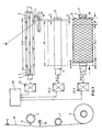
- the winding device consists of the traversing device 1 with reversing thread shaft 2 and traversing thread guide 3.
- the traversing thread guide 3 is guided back and forth in the grooves 4 of the reversing thread shaft and straight in the straight guide 5.
- the thread 6 is laid on the winding tube 7 to form a package 8.
- the sleeve 7 is firmly clamped on the winding spindle 9.1.
- the winding spindle 9.1 is driven in the direction of rotation 10 by the spindle motor 20.1.
- the second winding spindle 9.2 with the sleeve 7 clamped thereon is in the waiting position.
- the auxiliary thread guide 11 which will be described later, is still in the waiting position.
- the winding spindle 9.2 can be driven by a spindle motor 20.2.
- the traversing motor 31 is used to drive the traversing.
- the motors 31; 20.1; 20.2 can be started by programmable control device 30 independently of one another, put out of operation and controlled in their speed.
- the spindle speed decreases steadily because the thread speed remains constant while the bobbin diameter increases.
- the traversing speed remains essentially constant (wild winding) or changes only within narrowly specified limits (step precision winding).
- the coils can also be driven by the deflection roller.
- the guide roller rests on the surface of the spool and is driven at a constant speed.
- the traversing device also includes the deflection roller 21, which is partially wrapped around by the thread 6 and which either rests on the spool or only a very small one with the spool Gap forms, so that the drag length L1 of the thread between the deflection roller and the bobbin is very small.
- the traversing devices are mounted on a carriage 22 which is movable in the vertical direction and is sketched in FIG. 2. Details of the traversing device shown result, for example, from DE-PS 20 40 479 and 23 45 898. However, it is only an example. Other types of traversing devices are also conceivable, cf. for example EP 114 642 (EP-1321).
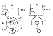
- the center distance between the deflection roller 21 and the full bobbin is first increased for the purpose of changing the bobbin, so that the deflection roller 21 completely releases the full bobbin 8.1.
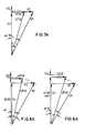
- the carrier 18 - as shown in FIG. 4 - is rotated in the direction of movement 24 until the winding spindle 9.2 with the empty tube 7.2 stretched thereon gets into the thread path.
- the laying stroke H predetermined by the traversing stroke CH of the thread guide 3, ie the spool length is reduced to the laying stroke H2.
- This reduced laying stroke H2 makes it possible to axially shift the winding spindle 9.1 with the direction of movement 15 by the amount A without the thread still located in the traversing device falling off the surface of the bobbin.
- winding spindle 9.2 with the empty tube 7 remains in its original position when the thread is changed, that is to say is not axially displaced.
- the winding spindle 9.1 is axially displaced with direction 15 such that, for example, the left end face of the full bobbin 8.1 coincides approximately with the left end of the shortened laying stroke.
- the axial displacement of the winding spindle 9.1 creates a distance B between the right end face of the full cheese 8 and the right end face of the new laying stroke H2, where B is greater than h, but less than 2h.
- auxiliary thread guide 11 is folded out of the position shown in broken lines in FIG. 1 into the thread running plane of the thread run 6.
- the thread is thereby lifted out of the traversing thread guide 3 and caught in the thread guide slot 56.
- FIG. 1 For this purpose, reference is made to FIG. 1.
- the movement length C of the auxiliary thread guide 11 over the right edge of the normal laying stroke H - indicated on the chuck 9.2 in dashed lines - is accordingly greater or at most equal to the distance that the catch slot 17 has from the right end of the normal laying stroke H.
- the length of movement C is less than the amount A of the axial displacement of the winding spindle 9.1. This ensures that - as shown in Fig. 1 - the thread can be brought into the normal plane of the catch slot, but also does not fall off the circumference of the full bobbin 8 and is still wound on the full bobbin during the catch and through the full coil is promoted.
- the catching device for textile threads is preferably attached as a slot on the circumference of the sleeve 7 and is located somewhat outside the winding area H.
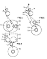
- the auxiliary thread guide 11 leads a very slow axial movement in and through the normal plane of the Catch slot so that the thread is caught safely. Now the auxiliary thread guide 11 is moved back at high speed into the area of the normal traverse stroke, so that - as can be seen from FIG. 1 - only a few turns of a thread reserve winding 26 are applied between the catch slot 17 and the right end side of the normal winding area H.
- auxiliary thread guide 11 As soon as the auxiliary thread guide 11 has reached the traversing area CH again, it is returned to its starting position, so that the thread is caught again by the traversing devices and moved to a package. Now the winding spindle 9.2 or the empty tube stretched thereon and the slide 22 are moved back into their starting position, the carrier 18 being rotated further accordingly.
- the operating position for the winding spindle 9.2 is shown in FIG. 6.
- Fig. 6 it is shown that the carriage 21 is now lowered again.
- the drive during winding that is to say in normal operation, can also be effected by a drive roller 20 which is driven at a constant peripheral speed and which is fastened on the carriage 22.
- the drive motors 20.1, 20.2 are switched off during normal operation of the winding.
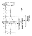
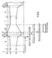
- FIGS. 7 to 9 show speed diagrams of the spool change. The process sequences proposed according to this invention are described on the basis of these speed diagrams.
- VU circumferential speed of the empty tube and the spool formed on it (circumferential speeds of 5,000 m / min are possible when winding man-made fibers;)
- VUW peripheral speed during reel change VC traversing speed (when winding synthetic fibers with a spool circumferential speed of 5,000 m / min, the traversing speed is 700 m / min to produce a crossing angle of, for example, 8 °.
- the traversing speed does not usually remain constant during the winding travel, but is changed according to certain programs around an average or within predetermined ranges. These changes are irrelevant in the context of this invention and are ignored in this application.
- the traversing speed is defined as the mean traversing speed.
- VCW traversing speed during the reel change VF thread speed (the thread speed is the geometric sum of the circumferential speed and the traversing speed. With a circumferential speed of 5,000 m / min and a traversing speed of 700 m / min, a thread speed of 5,050 m / min results. This means that when the The thread speed decreases by almost 1%.)
- the thread speed VF is the speed at which the thread is wound up. This speed is essentially identical to the speed at which the thread is delivered.
- the delivery mechanisms that deliver the thread at constant speed are not shown in FIGS. 1 to 5. They are common godets.
- alpha crossing angle (angle between the thread deposited on the bobbin and a tangent to the bobbin that intersects the thread.)
- alpha w crossing angle during the change phase.
- the mean value of the traversing speed is constant.
- the peripheral speed and the traversing speed add up to the constant value of the thread speed VF.
- the traversing speed can be reduced slightly (approx. 10 to 20%) in a phase II. This changes the crossing angle. This reduction is known per se and is not the subject of this application. Phase II is therefore not part of changing the bobbin, but part of the usual winding trip.
- the spool change according to this invention begins in phase III with the traversing speed steadily reaching a fraction of its setpoint, i.e. the value that the traversing speed at the end of the winding travel, i.e. at the end of phase II, preferably reduced by more than half.
- Phase III is initiated by the fact that - as shown in FIG. 3 - the carriage 22 is first raised and thus turned on sufficient distance between the deflection roller 21 and the full reel 8.1 is produced. With the strong reduction in the traversing speed which now begins, the rotation of the carrier 18 takes place at the same time, so that the distance between the deflecting roller 21 and the full reel 8.1 - as shown in FIGS. 4, 5 - increases increasingly. This also increases the drag length between the deflecting roller 21 and the full bobbin and thus tends to reduce the laying length of the thread on the bobbin. This reduction in the laying length compensates for the increase in the laying length that occurs due to the reduction in the traversing speed and is so great that the stroke shortening 2h explained with reference to FIG. 1 still occurs.
- This greatly reduced traversing speed can then be maintained for a short time in phase IV.
- the traversing speed is completely suspended.
- the traversing is suspended, as described above, by the thread being folded over by the auxiliary thread guide in the manner shown in FIG. 5 Phase of the bobbin change is lifted out of the traversing thread guide 3. Now the thread is placed on the empty tube 7 on the winding spindle 9.2 by axial movement of the auxiliary thread guide - as explained with reference to FIG. 1.
- phase VI After thread catching, a new bobbin is formed on the empty tube 7.
- the traversing speed in phase VI is used again with the last value. It should be mentioned that it is also possible to reinsert the traversing speed with a different value. If the traversing speed is reduced again starts, phase VII follows, in which a base layer of no more than 10% of the total layer thickness of the coil is formed and in which the traversing speed is steadily increased again to its setpoint. Part I of the winding cycle now follows, in which the traversing speed is kept at its preselected maximum value and is kept constant on average. The operating phases II, III, IV, V, VI then follow again.
- phase IV and phase VI in which the traversing speed is left at its reduced value, can be omitted.
- Phase II can also be omitted.
- the traversing speed remains at the value it has in phase I until the end of the winding cycle. It is also possible, after changing the bobbin, i.e. phase V to reinstate the traversing speed with any value between the value of operating phase I and the lowest value of operating phase III.
- the winding speed also decreases as the traversing speed decreases.
- the winding speed VF drops by an amount DV onto the peripheral speed VU of the spool.
- the jump in the thread relaxation is relatively small and therefore tolerable for the winding process.
- the peripheral speed is increased so much during the reduction of the traversing speed in operating phase III that the winding speed VF increases.
- the peripheral speed is increased up to the value of the desired winding speed.
- the actual value of the winding speed increases in phases III, IV, VI, VII above its setpoint. That means tet on the other hand that during the bobbin change phase, in which the traversing in operating phase V is suspended, the actual value of the winding speed is close to its setpoint, in the exemplary embodiment shown is exactly on its setpoint.
- the distance A is to be equated to the drag length L1 between the deflection roller 2 and the spool 8.1. It is thus the case that the deflecting roller 21 is attributable to the traversing device with regard to the filing law with which the thread is deposited on the bobbin. The thread is namely deposited on the bobbin as it is deposited on the deflection roller 21 by the traversing thread guide 3.
- the carriage 22 is raised at the beginning of phase III and the distance A between the guide roller and the spool is thus increased.
- This process can initially be carried out synchronously with the sharp reduction in the traversing speed taking place in phase III. The end of this increase in distance, however, is after the end of phase III. Then the distance A remains constant.
- the traversing speed is used again in phase VI.
- the carriage 22 is also lowered again, thereby reducing the distance between each guide roller and the new spool again.
- the carriage is preferably brought back into its operating position and the deflecting roller in contact with the spool before phase VII begins to increase the traversing speed.
- the traversing stroke that is to say the depositing length of the thread on the bobbin
- the bobbin is wound with a base layer which has a greater length than the rest of the bobbin.
- This reduction in the distance preferably takes place after the traversing speed has been reinstated, that is to say after phase V has ended.
- the reduction in the distance and the simultaneous increase in the traversing speed both contribute to the formation of the conical base layer.
Landscapes
- Winding Filamentary Materials (AREA)
- Coiling Of Filamentary Materials In General (AREA)
- Replacing, Conveying, And Pick-Finding For Filamentary Materials (AREA)
Applications Claiming Priority (6)
| Application Number | Priority Date | Filing Date | Title |
|---|---|---|---|
| DE3822862 | 1988-07-06 | ||
| DE19883822862 DE3822862A1 (de) | 1988-07-06 | 1988-07-06 | Verfahren zum spulenwechsel |
| DE3823774 | 1988-07-14 | ||
| DE3823774 | 1988-07-14 | ||
| DE3905205 | 1989-02-21 | ||
| DE3905205 | 1989-02-21 |
Publications (3)
| Publication Number | Publication Date |
|---|---|
| EP0349939A2 true EP0349939A2 (fr) | 1990-01-10 |
| EP0349939A3 EP0349939A3 (fr) | 1992-02-12 |
| EP0349939B1 EP0349939B1 (fr) | 1994-10-19 |
Family
ID=27197884
Family Applications (1)
| Application Number | Title | Priority Date | Filing Date |
|---|---|---|---|
| EP89112057A Expired - Lifetime EP0349939B1 (fr) | 1988-07-06 | 1989-07-01 | Procédé pour le changement de bobines |
Country Status (4)
| Country | Link |
|---|---|
| US (1) | US4917319A (fr) |
| EP (1) | EP0349939B1 (fr) |
| DE (1) | DE58908513D1 (fr) |
| ES (1) | ES2061806T3 (fr) |
Families Citing this family (8)
| Publication number | Priority date | Publication date | Assignee | Title |
|---|---|---|---|---|
| US5156347A (en) * | 1988-03-30 | 1992-10-20 | Gay Ii Francis V | Automatic continuous fiber winder |
| DE59005704D1 (de) * | 1989-04-06 | 1994-06-23 | Rieter Ag Maschf | Spulautomat. |
| EP0450085B1 (fr) * | 1989-09-27 | 1997-10-22 | Kamitsu Seisakusho Ltd. | Dispositif de bobinage de fil du type tourelle |
| US5489067A (en) * | 1989-09-27 | 1996-02-06 | Kamitsu Seisakusho, Ltd. | Turret type precision yarn winder |
| DE19634926A1 (de) * | 1996-08-29 | 1998-03-05 | Neumag Gmbh | Vorrichtung zum ununterbrochenen Aufwickeln von Fäden |
| US6158689A (en) * | 1997-07-10 | 2000-12-12 | Barmag-Spinnzwirn Gmbh | Yarn winding apparatus and method |
| DE29908962U1 (de) * | 1999-05-21 | 1999-09-02 | Neumag - Neumünstersche Maschinen- und Anlagenbau GmbH, 24536 Neumünster | Aufspulmaschine |
| JP2012144323A (ja) * | 2011-01-11 | 2012-08-02 | Tmt Machinery Inc | 紡糸巻取装置及び紡糸巻取設備 |
Family Cites Families (13)
| Publication number | Priority date | Publication date | Assignee | Title |
|---|---|---|---|---|
| JPS5417860B2 (fr) * | 1973-12-24 | 1979-07-03 | ||
| US4033519A (en) * | 1974-06-06 | 1977-07-05 | Teijin Limited | Method and apparatus for automatically changing bobbins and winding yarn continuously |
| DD122503A1 (fr) * | 1974-12-23 | 1976-10-12 | ||
| JPS54114675A (en) * | 1978-02-28 | 1979-09-06 | Toray Ind Inc | Turret type thread stripe winder |
| DE3211603C2 (de) * | 1981-04-04 | 1984-11-08 | Barmag Barmer Maschinenfabrik Ag, 5630 Remscheid | Verfahren zum verlustfreien Spulenwechsel beim Aufspulen eines kontinuierlich zulaufenden Fadens sowie Aufspulvorrichtung |
| IT1151367B (it) * | 1981-04-04 | 1986-12-17 | Barmag Barmer Maschf | Procedimento per il cambio della bobina durante l'avvolgimento di un filo alimentato in continuazione,nonche' dispositivo d'avvolgimento |
| JPS5878953A (ja) * | 1981-11-04 | 1983-05-12 | Teijin Ltd | 糸条巻取装置 |
| US4504021A (en) * | 1982-03-20 | 1985-03-12 | Barmag Barmer Maschinenfabrik Ag | Ribbon free wound yarn package and method and apparatus for producing the same |
| US4504024A (en) * | 1982-05-11 | 1985-03-12 | Barmag Barmer Maschinenfabrik Ag | Method and apparatus for producing ribbon free wound yarn package |
| DE3723524C2 (de) * | 1986-07-23 | 1996-07-04 | Barmag Barmer Maschf | Kreuzspule und Verfahren zur Herstellung einer Kreuzspule |
| DE3627081C2 (de) * | 1986-08-09 | 1995-08-03 | Barmag Barmer Maschf | Verfahren zum Aufwickeln von Fäden |
| DE3761556D1 (de) * | 1986-08-09 | 1990-03-08 | Barmag Barmer Maschf | Verfahren zum aufwickeln von faeden. |
| DE3627879C2 (de) * | 1986-08-16 | 1995-09-28 | Barmag Barmer Maschf | Verfahren zum Aufwickeln von Fäden |
-
1989
- 1989-06-30 US US07/374,963 patent/US4917319A/en not_active Expired - Fee Related
- 1989-07-01 ES ES89112057T patent/ES2061806T3/es not_active Expired - Lifetime
- 1989-07-01 DE DE58908513T patent/DE58908513D1/de not_active Expired - Fee Related
- 1989-07-01 EP EP89112057A patent/EP0349939B1/fr not_active Expired - Lifetime
Also Published As
| Publication number | Publication date |
|---|---|
| US4917319A (en) | 1990-04-17 |
| EP0349939A3 (fr) | 1992-02-12 |
| ES2061806T3 (es) | 1994-12-16 |
| EP0349939B1 (fr) | 1994-10-19 |
| DE58908513D1 (de) | 1994-11-24 |
Similar Documents
| Publication | Publication Date | Title |
|---|---|---|
| EP0374536B1 (fr) | Machine de bobinage | |
| EP0237892B1 (fr) | Procédé et dispositif pour rebobiner des fils | |
| EP0195325B1 (fr) | Procédé de bobinage | |
| EP0256411B1 (fr) | Méthode pour embobiner des fils | |
| DE3805347A1 (de) | Aufspulmaschine | |
| EP0094483A1 (fr) | Commande de broche de bobinage | |
| CH656865A5 (de) | Verfahren zum spulenwechsel beim aufspulen eines staendig anlaufenden fadens und aufspulvorrichtung. | |
| CH698687A2 (de) | Verfahren zur Steuerung einer von einem einzelmotorischen Antrieb angetriebenen Changiereinrichtung an einer Vorrichtung zum Wickeln konischer Kreuzspulen sowie eine Kreuzspulen herstellende Textilmaschine. | |
| DE102008060788A1 (de) | Verfahren und Vorrichtung zum Wickeln einer Fadenspule | |
| EP0256383B1 (fr) | Méthode pour embobiner des fils | |
| DE102012023557A1 (de) | Verfahren zum Steuern der Beschleunigung einer Spulenantriebswalze | |
| EP0349939B1 (fr) | Procédé pour le changement de bobines | |
| EP2595907B1 (fr) | Procédé de fabrication d'une bobine textile et poste de travail pour mettre en oeuvre le procédé | |
| DE10342266B4 (de) | Verfahren zum Herstellen einer Kreuzspule | |
| EP0521816B1 (fr) | Procédé pour transferer le fil d'une bobine pleine à une bobine vide et un bobinoir | |
| EP2738123B1 (fr) | Procédé de régulation de l'accélération d'un rouleau d'entraînement de bobine | |
| WO2007057109A1 (fr) | Procede pour eviter l'enroulage en ruban | |
| DE4112768A1 (de) | Verfahren zum wickeln von kreuzspulen | |
| EP2468669B1 (fr) | Procédé de fabrication d'une bobine de teinture | |
| EP0018577A1 (fr) | Procédé et dispositif pour mettre en place automatiquement un fil sur une bobine | |
| DE3211603C2 (de) | Verfahren zum verlustfreien Spulenwechsel beim Aufspulen eines kontinuierlich zulaufenden Fadens sowie Aufspulvorrichtung | |
| EP1758807A1 (fr) | Procede et dispositif pour enrouler une bobine de fil | |
| DE3909106A1 (de) | Aufspulmaschine | |
| DE3822862A1 (de) | Verfahren zum spulenwechsel | |
| DE60120253T2 (de) | Elastisches-Garn Wickel und Verfahren zum Betrieb einer Aufwickelmaschine für elastische Garne |
Legal Events
| Date | Code | Title | Description |
|---|---|---|---|
| PUAI | Public reference made under article 153(3) epc to a published international application that has entered the european phase |
Free format text: ORIGINAL CODE: 0009012 |
|
| AK | Designated contracting states |
Kind code of ref document: A2 Designated state(s): CH DE ES FR GB IT LI |
|
| PUAL | Search report despatched |
Free format text: ORIGINAL CODE: 0009013 |
|
| AK | Designated contracting states |
Kind code of ref document: A3 Designated state(s): CH DE ES FR GB IT LI |
|
| 17P | Request for examination filed |
Effective date: 19920204 |
|
| 17Q | First examination report despatched |
Effective date: 19931123 |
|
| ITF | It: translation for a ep patent filed | ||
| GRAA | (expected) grant |
Free format text: ORIGINAL CODE: 0009210 |
|
| AK | Designated contracting states |
Kind code of ref document: B1 Designated state(s): CH DE ES FR GB IT LI |
|
| REF | Corresponds to: |
Ref document number: 58908513 Country of ref document: DE Date of ref document: 19941124 |
|
| ET | Fr: translation filed | ||
| REG | Reference to a national code |
Ref country code: ES Ref legal event code: FG2A Ref document number: 2061806 Country of ref document: ES Kind code of ref document: T3 |
|
| GBT | Gb: translation of ep patent filed (gb section 77(6)(a)/1977) |
Effective date: 19950117 |
|
| PGFP | Annual fee paid to national office [announced via postgrant information from national office to epo] |
Ref country code: FR Payment date: 19950619 Year of fee payment: 7 |
|
| PGFP | Annual fee paid to national office [announced via postgrant information from national office to epo] |
Ref country code: GB Payment date: 19950620 Year of fee payment: 7 |
|
| PGFP | Annual fee paid to national office [announced via postgrant information from national office to epo] |
Ref country code: ES Payment date: 19950710 Year of fee payment: 7 |
|
| PGFP | Annual fee paid to national office [announced via postgrant information from national office to epo] |
Ref country code: DE Payment date: 19950729 Year of fee payment: 7 |
|
| PGFP | Annual fee paid to national office [announced via postgrant information from national office to epo] |
Ref country code: CH Payment date: 19950731 Year of fee payment: 7 |
|
| PLBE | No opposition filed within time limit |
Free format text: ORIGINAL CODE: 0009261 |
|
| STAA | Information on the status of an ep patent application or granted ep patent |
Free format text: STATUS: NO OPPOSITION FILED WITHIN TIME LIMIT |
|
| 26N | No opposition filed | ||
| PG25 | Lapsed in a contracting state [announced via postgrant information from national office to epo] |
Ref country code: GB Effective date: 19960701 |
|
| PG25 | Lapsed in a contracting state [announced via postgrant information from national office to epo] |
Ref country code: ES Free format text: LAPSE BECAUSE OF EXPIRATION OF PROTECTION Effective date: 19960702 |
|
| PG25 | Lapsed in a contracting state [announced via postgrant information from national office to epo] |
Ref country code: LI Effective date: 19960731 Ref country code: CH Effective date: 19960731 |
|
| GBPC | Gb: european patent ceased through non-payment of renewal fee |
Effective date: 19960701 |
|
| REG | Reference to a national code |
Ref country code: CH Ref legal event code: PL |
|
| PG25 | Lapsed in a contracting state [announced via postgrant information from national office to epo] |
Ref country code: FR Effective date: 19970328 |
|
| PG25 | Lapsed in a contracting state [announced via postgrant information from national office to epo] |
Ref country code: DE Effective date: 19970402 |
|
| REG | Reference to a national code |
Ref country code: FR Ref legal event code: ST |
|
| REG | Reference to a national code |
Ref country code: ES Ref legal event code: FD2A Effective date: 19990601 |
|
| PG25 | Lapsed in a contracting state [announced via postgrant information from national office to epo] |
Ref country code: IT Free format text: LAPSE BECAUSE OF NON-PAYMENT OF DUE FEES;WARNING: LAPSES OF ITALIAN PATENTS WITH EFFECTIVE DATE BEFORE 2007 MAY HAVE OCCURRED AT ANY TIME BEFORE 2007. THE CORRECT EFFECTIVE DATE MAY BE DIFFERENT FROM THE ONE RECORDED. Effective date: 20050701 |