EP0350049A2 - Verfahren und System zum Erzeugen eines Alarmsignals in einem automatischen chemischen Analysegerät - Google Patents
Verfahren und System zum Erzeugen eines Alarmsignals in einem automatischen chemischen Analysegerät Download PDFInfo
- Publication number
- EP0350049A2 EP0350049A2 EP89112395A EP89112395A EP0350049A2 EP 0350049 A2 EP0350049 A2 EP 0350049A2 EP 89112395 A EP89112395 A EP 89112395A EP 89112395 A EP89112395 A EP 89112395A EP 0350049 A2 EP0350049 A2 EP 0350049A2
- Authority
- EP
- European Patent Office
- Prior art keywords
- alarm
- change
- chemical analysis
- sound data
- sound
- Prior art date
- Legal status (The legal status is an assumption and is not a legal conclusion. Google has not performed a legal analysis and makes no representation as to the accuracy of the status listed.)
- Withdrawn
Links
Images

Classifications
-
- G—PHYSICS
- G08—SIGNALLING
- G08B—SIGNALLING SYSTEMS, e.g. PERSONAL CALLING SYSTEMS; ORDER TELEGRAPHS; ALARM SYSTEMS
- G08B3/00—Audible signalling systems, e.g. audible personal calling systems
- G08B3/10—Audible signalling systems, e.g. audible personal calling systems using electric transmission; using electromagnetic transmission
-
- G—PHYSICS
- G01—MEASURING; TESTING
- G01N—INVESTIGATING OR ANALYSING MATERIALS BY DETERMINING THEIR CHEMICAL OR PHYSICAL PROPERTIES
- G01N35/00—Automatic analysis not limited to methods or materials provided for in any single one of groups G01N1/00 - G01N33/00; Handling materials therefor
-
- G—PHYSICS
- G01—MEASURING; TESTING
- G01N—INVESTIGATING OR ANALYSING MATERIALS BY DETERMINING THEIR CHEMICAL OR PHYSICAL PROPERTIES
- G01N35/00—Automatic analysis not limited to methods or materials provided for in any single one of groups G01N1/00 - G01N33/00; Handling materials therefor
- G01N35/10—Devices for transferring samples or any liquids to, in, or from, the analysis apparatus, e.g. suction devices, injection devices
- G01N35/1009—Characterised by arrangements for controlling the aspiration or dispense of liquids
- G01N2035/1025—Fluid level sensing
Definitions
- the present invention relates to a method and system for generating an alarm in an automatic chemical analysis apparatus.
- a conventional automatic chemical analysis apparatus causes a solution sampled from a serum of a human body with a predetermined reagent to measure a concentration of a solution reactecd by colorimetry or the like, thereby analyzing predetermined items such as total protein (TP), uric acid (UA), and a triglyceride (TG).
- predetermined items such as total protein (TP), uric acid (UA), and a triglyceride (TG).
- Fig. 1 is a schematic view showing an arrangement of an automatic chemical analysis apparatus.
- a plurality of reaction containers 3a, 3b, 3c,... are placed in constant-temperature water 2 in a thermostat 1 and are moved by a predetermined cycle in a direction of an arrow.
- a sample distributing probe 4, a first reagent distributing probe 5, a second reagent distributing probe 6, and a stirrer 7 are located at peripheral positions A, B, C, and D of the thermostat 1, respectively.
- the sample solution is distributed by the sample distributing probe 4 to the reaction container 3d located at the position A.
- the first reagent is distributed by the first reagent distributing probe 5 to the reaction container 3e located at the position B.
- the second reagent is distributed by the second reagent distributing probe 6 to the reaction container 3f located at the position C.
- the sample solution and the reagent in the reaction container 3g located at the position D are stirred by the stirrer 7.
- the number of reagents is not limited to two.
- a light source 8 located at the central position of the thermostat 1. This light is transmitted through a reaction solution (containing both the sample solution and the reagent) of each reaction container. Light transmitted through the reaction container is detected by a photometric system having a diffraction grating 9 and a detector 10. Therefore, the concentration of a specific component of the reaction solution can be analyzed.
- a plurality of automatic chemical analysis apparatuses are installed in medical organizations such as a large examination center to systematize automatic analysis of a large quantity.
- manipulations and maintenance of each apparatus are performed by special operators.
- the special operators cannot always check each apparatus.
- an alarm unit such as a buzzer is arranged in each apparatus.
- a conventional alarm sound does not represent a level of the change. That is, the alarm sound is generated regardless of the fact whether the change is related to an apparatus failure. For this reason, the load on the operator is increased.
- the operator need not immediately handle because samples contained in other reaction containers can be analyzed and samples for the empty containers can then be analyzed. In this case, if a level of the change in the apparatus can be signaled to the operator, the load on the operator can be reduced.
- a method of generating an alarm signal in an automatic chemical analysis apparatus comprising the steps of: storing sound data; detecting a level of change in the automatic chemical analysis apparatus; reading out the sound data corresponding to the level of change; and generating the alarm signal in accordance with the readout sound data.
- a system for generating an alarm signal in an automatic chemical analysis apparatus comprising: storing means for storing sound data; detecting means for detecting a level of change in the automatic chemical analysis apparatus; and generating means for generating the alarm signal in accordance with the stored sound data corresponding to the level of change.
- automatic chemical analysis apparatuses 12a to 12e installed in an examination room 11 perform chemical analysis according to colorimetry as in the apparatus shown in Fig. 1.
- the apparatuses 12a to 12e perform other chemical analysis using an electrode method, an immunoanalysis method and the like.
- the apparatuses 12a to 12e have alarm units 13a to 13e.
- the alarm units 13a to 13e generate alarm signals having a tone and a voice.
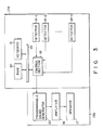
- the alarm unit 13a comprises a PSG (Programmable Sound Generator) 20, an amplifier 16, and a speaker 17.
- An audible frequency (20 to 20,000 Hz) sound signal output from the PSG 20 is amplified to a predetermined level by the amplifier 16, and the amplified signal is output as an alarm signal to the speaker 17.
- the alarm units 13b to 13e have the same arrangement as that of the alarm unit 13a and generate different alarm sounds from the corresponding speakers.
- a detector 18-1 for detecting a change (primarily a mechanical change of the apparatus) associated with a failure of the apparatus, a detector 18-2 for detecting a shortage of reagents,... a detector 18-n for detecting an end of chemical analysis are arranged at predetermined positions of the apparatus 12a.
- a predetermined one of the detectors 18-1 to 18-n detects the change.
- a detection signal from this detector is input to a control section 19 including a microprocessor.
- a RAM 30 and a keyboard 31 are connected to the control section 19 through a bus 35.
- the control section 19 reads out sound data from the RAM 30 on the basis of the detection signal and outputs the readout sound data to the PSG 20. Therefore, a predetermined alarm sound is generated from the speaker 17.
- the RAM 30 stores sound data representing alarm sounds corresponding to change levels. As described above, sound data representing different alarm sounds are stored in each apparatus when a plurality of apparatuses are installed in a single examination room. These sound data include tone data and voice data.
- the operator can immediately distinguish the automatic chemical analysis apparatus which is currently generating the alarm sound. Easy distinction can also be achieved by generating voice sounds corresponding to the alarm units 13a to 13e from the speakers 17.
- the volume of the alarm sound can be controlled in accordance with the installation environments.
- the alarm unit having a sound source for generating an electronic sound can be arranged at low cost due to the recent development of the electronic techniques.
- the sound source is not limited to an electronic sound source, but other sound sources may be used to generate different alarm sounds.
Landscapes
- Physics & Mathematics (AREA)
- General Physics & Mathematics (AREA)
- Health & Medical Sciences (AREA)
- Life Sciences & Earth Sciences (AREA)
- Chemical & Material Sciences (AREA)
- Analytical Chemistry (AREA)
- Biochemistry (AREA)
- General Health & Medical Sciences (AREA)
- Immunology (AREA)
- Pathology (AREA)
- Electromagnetism (AREA)
- Automatic Analysis And Handling Materials Therefor (AREA)
Applications Claiming Priority (2)
| Application Number | Priority Date | Filing Date | Title |
|---|---|---|---|
| JP16680588A JPH0217447A (ja) | 1988-07-06 | 1988-07-06 | 自動化学分析システム |
| JP166805/88 | 1988-07-06 |
Publications (2)
| Publication Number | Publication Date |
|---|---|
| EP0350049A2 true EP0350049A2 (de) | 1990-01-10 |
| EP0350049A3 EP0350049A3 (de) | 1991-03-20 |
Family
ID=15838005
Family Applications (1)
| Application Number | Title | Priority Date | Filing Date |
|---|---|---|---|
| EP19890112395 Withdrawn EP0350049A3 (de) | 1988-07-06 | 1989-07-06 | Verfahren und System zum Erzeugen eines Alarmsignals in einem automatischen chemischen Analysegerät |
Country Status (2)
| Country | Link |
|---|---|
| EP (1) | EP0350049A3 (de) |
| JP (1) | JPH0217447A (de) |
Cited By (5)
| Publication number | Priority date | Publication date | Assignee | Title |
|---|---|---|---|---|
| EP0485831A1 (de) * | 1990-11-13 | 1992-05-20 | F. Hoffmann-La Roche Ag | Automatisches Analysengerät |
| US5154766A (en) * | 1991-11-15 | 1992-10-13 | Engelhard Corporation | Method for controlling shade of hydrous kaolin pigments and products obtained therefrom |
| FR2688110A1 (fr) * | 1992-03-02 | 1993-09-03 | Accumulateurs Fixes | Systeme de commande pour installation dotee de blocs autonomes d'alarme sonore. |
| EP0672906A1 (de) * | 1994-03-18 | 1995-09-20 | Hitachi, Ltd. | Automatisierte Analysator |
| WO1997022882A1 (en) * | 1995-12-18 | 1997-06-26 | Alan Norman Hale | Sample processing apparatus and method |
Family Cites Families (5)
| Publication number | Priority date | Publication date | Assignee | Title |
|---|---|---|---|---|
| US4218610A (en) * | 1976-04-28 | 1980-08-19 | J. T. Baker Chemical Co. | Automatic blood analyzing system |
| US4661319A (en) * | 1984-04-06 | 1987-04-28 | Boehringer Mannheim Diagnostics, Inc. | Blood transfer assembly |
| JPH0776771B2 (ja) * | 1984-07-30 | 1995-08-16 | 株式会社東芝 | 自動化学分析装置 |
| GB8423369D0 (en) * | 1984-09-15 | 1984-10-17 | Snell J D | Monitoring of liquids |
| DE3742827A1 (de) * | 1987-01-09 | 1988-08-25 | Hoelter Heinz | Vorrichtung zum aufspueren und zur warnsignalgebung bei vorhandensein von gefaehrdenden gasfoermigen stoffen, insbesondere fluessiggas |
-
1988
- 1988-07-06 JP JP16680588A patent/JPH0217447A/ja active Pending
-
1989
- 1989-07-06 EP EP19890112395 patent/EP0350049A3/de not_active Withdrawn
Cited By (7)
| Publication number | Priority date | Publication date | Assignee | Title |
|---|---|---|---|---|
| EP0485831A1 (de) * | 1990-11-13 | 1992-05-20 | F. Hoffmann-La Roche Ag | Automatisches Analysengerät |
| US5154766A (en) * | 1991-11-15 | 1992-10-13 | Engelhard Corporation | Method for controlling shade of hydrous kaolin pigments and products obtained therefrom |
| FR2688110A1 (fr) * | 1992-03-02 | 1993-09-03 | Accumulateurs Fixes | Systeme de commande pour installation dotee de blocs autonomes d'alarme sonore. |
| EP0559554A1 (de) * | 1992-03-02 | 1993-09-08 | Saft | Steuerungssystem für Vorrichtung mit autonomen Blöcken von Tonalarm |
| EP0672906A1 (de) * | 1994-03-18 | 1995-09-20 | Hitachi, Ltd. | Automatisierte Analysator |
| US5695718A (en) * | 1994-03-18 | 1997-12-09 | Hitachi, Ltd. | Automatic analyzer |
| WO1997022882A1 (en) * | 1995-12-18 | 1997-06-26 | Alan Norman Hale | Sample processing apparatus and method |
Also Published As
| Publication number | Publication date |
|---|---|
| JPH0217447A (ja) | 1990-01-22 |
| EP0350049A3 (de) | 1991-03-20 |
Similar Documents
| Publication | Publication Date | Title |
|---|---|---|
| JP2996860B2 (ja) | 自動分析装置 | |
| US4202033A (en) | Apparatus and method utilizing calculator for quality control of hematology sample analysis | |
| IL75464A0 (en) | Immuno-assay system and method and apparatus for analysis | |
| JP2003315348A (ja) | 検体処理システム及びそれを用いた検体検査自動化システム | |
| EP0397424A3 (de) | Mehrfachanalysesystem | |
| JP3610345B2 (ja) | 分析装置 | |
| EP2015078A1 (de) | Automatisches Analysegerät und Analyseverfahren damit | |
| JP2000275249A (ja) | 自動分析装置 | |
| EP1215502A1 (de) | Automatischer chemischer Analysator | |
| EP2554998A1 (de) | Probenanalysesystem | |
| JP3314546B2 (ja) | 自動分析装置 | |
| CN101435828B (zh) | 分析仪及限制分析仪中应用程序功能的方法 | |
| JP7246498B2 (ja) | 複合型自動分析装置、システム、及び異常判定方法 | |
| US5354996A (en) | Metal ion monitoring system | |
| JPH0217447A (ja) | 自動化学分析システム | |
| JP2009264884A (ja) | 検体処理システム | |
| EP4303576B1 (de) | Elektrolytmessvorrichtung und verfahren zur bestimmung einer anomalie in einer elektrolytkonzentrationsmesseinheit | |
| JP3109443U (ja) | 自動分析装置 | |
| JP4920450B2 (ja) | 自動分析装置及びその精度管理方法 | |
| JPS6125058A (ja) | クロマトグラフにおける異常値確認方法 | |
| JP2603727B2 (ja) | 自動分注装置 | |
| JP3426100B2 (ja) | 感知器およびその試験方法 | |
| JPH01221672A (ja) | 自動化学分析装置 | |
| JPH05302847A (ja) | 電子天びん | |
| Brown et al. | Microcomputer control and data system for automated multiple flow injection analysis |
Legal Events
| Date | Code | Title | Description |
|---|---|---|---|
| PUAI | Public reference made under article 153(3) epc to a published international application that has entered the european phase |
Free format text: ORIGINAL CODE: 0009012 |
|
| 17P | Request for examination filed |
Effective date: 19890706 |
|
| AK | Designated contracting states |
Kind code of ref document: A2 Designated state(s): DE FR GB NL |
|
| PUAL | Search report despatched |
Free format text: ORIGINAL CODE: 0009013 |
|
| AK | Designated contracting states |
Kind code of ref document: A3 Designated state(s): DE FR GB NL |
|
| 17Q | First examination report despatched |
Effective date: 19930121 |
|
| STAA | Information on the status of an ep patent application or granted ep patent |
Free format text: STATUS: THE APPLICATION IS DEEMED TO BE WITHDRAWN |
|
| 18D | Application deemed to be withdrawn |
Effective date: 19940607 |