EP0350060A2 - Elément d'alimentation d'un film mince pour une machine de revêtement par films minces - Google Patents
Elément d'alimentation d'un film mince pour une machine de revêtement par films minces Download PDFInfo
- Publication number
- EP0350060A2 EP0350060A2 EP89112471A EP89112471A EP0350060A2 EP 0350060 A2 EP0350060 A2 EP 0350060A2 EP 89112471 A EP89112471 A EP 89112471A EP 89112471 A EP89112471 A EP 89112471A EP 0350060 A2 EP0350060 A2 EP 0350060A2
- Authority
- EP
- European Patent Office
- Prior art keywords
- thin film
- feed member
- groove
- vacuum
- row
- Prior art date
- Legal status (The legal status is an assumption and is not a legal conclusion. Google has not performed a legal analysis and makes no representation as to the accuracy of the status listed.)
- Ceased
Links
Images

Classifications
-
- B—PERFORMING OPERATIONS; TRANSPORTING
- B32—LAYERED PRODUCTS
- B32B—LAYERED PRODUCTS, i.e. PRODUCTS BUILT-UP OF STRATA OF FLAT OR NON-FLAT, e.g. CELLULAR OR HONEYCOMB, FORM
- B32B37/00—Methods or apparatus for laminating, e.g. by curing or by ultrasonic bonding
- B32B37/14—Methods or apparatus for laminating, e.g. by curing or by ultrasonic bonding characterised by the properties of the layers
- B32B37/16—Methods or apparatus for laminating, e.g. by curing or by ultrasonic bonding characterised by the properties of the layers with all layers existing as coherent layers before laminating
- B32B37/22—Methods or apparatus for laminating, e.g. by curing or by ultrasonic bonding characterised by the properties of the layers with all layers existing as coherent layers before laminating involving the assembly of both discrete and continuous layers
- B32B37/223—One or more of the layers being plastic
- B32B37/226—Laminating sheets, panels or inserts between two continuous plastic layers
-
- B—PERFORMING OPERATIONS; TRANSPORTING
- B29—WORKING OF PLASTICS; WORKING OF SUBSTANCES IN A PLASTIC STATE IN GENERAL
- B29C—SHAPING OR JOINING OF PLASTICS; SHAPING OF MATERIAL IN A PLASTIC STATE, NOT OTHERWISE PROVIDED FOR; AFTER-TREATMENT OF THE SHAPED PRODUCTS, e.g. REPAIRING
- B29C31/00—Handling, e.g. feeding of the material to be shaped, storage of plastics material before moulding; Automation, i.e. automated handling lines in plastics processing plants, e.g. using manipulators or robots
-
- B—PERFORMING OPERATIONS; TRANSPORTING
- B29—WORKING OF PLASTICS; WORKING OF SUBSTANCES IN A PLASTIC STATE IN GENERAL
- B29C—SHAPING OR JOINING OF PLASTICS; SHAPING OF MATERIAL IN A PLASTIC STATE, NOT OTHERWISE PROVIDED FOR; AFTER-TREATMENT OF THE SHAPED PRODUCTS, e.g. REPAIRING
- B29C2791/00—Shaping characteristics in general
- B29C2791/004—Shaping under special conditions
- B29C2791/006—Using vacuum
-
- B—PERFORMING OPERATIONS; TRANSPORTING
- B29—WORKING OF PLASTICS; WORKING OF SUBSTANCES IN A PLASTIC STATE IN GENERAL
- B29L—INDEXING SCHEME ASSOCIATED WITH SUBCLASS B29C, RELATING TO PARTICULAR ARTICLES
- B29L2031/00—Other particular articles
- B29L2031/34—Electrical apparatus, e.g. sparking plugs or parts thereof
- B29L2031/3425—Printed circuits
-
- B—PERFORMING OPERATIONS; TRANSPORTING
- B32—LAYERED PRODUCTS
- B32B—LAYERED PRODUCTS, i.e. PRODUCTS BUILT-UP OF STRATA OF FLAT OR NON-FLAT, e.g. CELLULAR OR HONEYCOMB, FORM
- B32B2457/00—Electrical equipment
- B32B2457/08—PCBs, i.e. printed circuit boards
Definitions
- the present invention relates to the art of adhering a thin film to a base plate, and particularly relates to a thin film feed member in a thin film adhering apparatus for feeding a thin film to a base plate.
- a printed circuit board for an electronic appliance such as a computer
- wirings are made of copper or the like in a prescribed pattern on one or both sides of an electrically insulating base plate.
- a conventional thin film adhering apparatus in which a thin stratified film consisting of a protective film and a resist film or the like is adhered to an electrically insulating base plate in a process of manufacturing a printed circuit board, the leading edge of the thin stratified film is sucked onto a suction surface of a thin stratified film tentative sticking member by a vacuum at the start of the adhering operation so that the leading edge of the film is moved toward the base plate as the leading edge remains sucked on the suction surface, as described in the Japanese Patent Application (OPI) No.
- the continuous thin film can be cut to a prescribed length corresponding to the size of the base plate, without suspending the adhesion of the thin film to the base plate.
- the thin film feed member functions so that the thin film is sucked and held on the member by suction at the time of the tentative sticking of the thin film and the cutoff thereof.
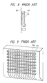
- the suction surface of the thin film feed member has grooves 103 extending in the transverse direction of the thin film 102, and has vacuum suction holes 104 in both the grooved and ungrooved portions of the suction surface.
- a thin film to be adhered to a base plate by the conventional apparatus may have several possible widths, such as, 195 mm, 245 mm, 295 mm, 330 mm, 400 mm, 495 mm. 600 mm and so forth, the grooves 103 of the suction surface of the thin film feed member are formed and disposed based on only a single width of a thin film, such as 600 mm, for example. For that reason, when a thin film whose width is smaller than 600 mm is sucked onto the thin film feed member so as to be moved toward the base plate, a gap arises between the film and the groove 103 such that several of the holes 104 will not be covered by the thin film. Since gas sucked through the vacuum suction holes 104 leaks through the gap to make it impossible to securely suck the thin film onto the suction surface of the thin film feed member, the thin film is likely to be wrinkled so as to result in a defective product.
- the present invention was made in order to solve the above problem. Accordingly, it is an object of the present invention to provide a thin film feed member on which a supplied thin film can be securely vacuum adhered without wrinkling the film, regardless of the size of the film.
- the thin film feed member in accordance with the present invention has rows of grooves, each row having a longitudinal direction transverse to the feed direction of the thin film.
- Each row groove is discontinuous, in the longitudinal direction, consisting of groove sections whose edges rise to the feed surface of the film feed member.
- the spacing of the groove sections are such that each standard thin film width will completely cover a number of groove sections, without introduction of air gaps.
- the center groove section per row is preferably of a length slightly less than the smallest standard width of thin film, and the extreme end groove sections per row are positioned to be slightly inward of the largest standard width of thin film.
- the other groove sections are likewise positioned relative to standard or expected widths of thin films to be fed by the thin film feeder member. In this way each thin film will completely cover groove sections, with no partial covering as in the prior art. The consequence is that the vacuum attraction is stronger, more efficient and leads to secure adhesion of the film to the feeder.
- the suction chamber of the thin film feed member which is for the thin film suction surface thereof, may be divided into a prescribed number of suction chambers at intervals in the transverse direction of each of the thin films depending on the widths of the films.
- the thin film feed member provided in accordance with the present invention has a thin film suction surface having grooves which are discontinuous, and the portions of the groove section depends on the widths of the films to be fed. This arrangement prevents a gas leak gap from occurring between each of the grooves and each of the thin films. As a result, each of the thin films can be securely vacuum adhered onto the thin film suction surface of the member without wrinkling the film. If the suction chamber of the member is divided into the plural suction chambers at the intervals in the transverse direction of each of the thin films depending on the widths of the films, each film can be securely and efficiently sucked onto the thin film suction surface of the member.
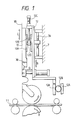
- Fig. 1 shows a thin film feed member 10, which is hereinafter referred to as the main vacuum suction plate. Except for the main vacuum suction plate 10, the thin film adhesion apparatus is the same as that disclosed in the above-mentioned Japanese Patent Application No. 264236/86. For that reason, the apparatus is not described in detail herein.
- the main vacuum suction plate 10 is provided on a support member 12 which is moved toward and away from the base plate 11 in directions B shown by arrows in Fig. 1.
- the support member 12 is provided on the body 7 of the apparatus so that the member can be slid on a guide member 7A in the directions B.
- the plate 10 and member 12 illustrated constitutes an upper main vacuum suction plate and an upper support member.
- a lower plate 10 and a lower member 12 provided under the conveyance passage of the base plate 11.
- the upper support member 12 and the lower support member 12 are movably coupled to each other by a rack and pinion mechanism so that the support members are simultaneously moved toward and away from each other by a driver provided on the lower support member.
- the rack and pinion mechanism includes racks 12A provided on the support members 12, and a pinion 12B engaged with the racks.
- the driver is made of a pneumatic cylinder, for example. However, the driver may be made of a hydraulic cylinder, an electromagnetic cylinder, a combination of a step motor and a mechanism for transmitting a motive power of the motor to the support members 12, or the like.
- the main vacuum suction plates 10 are provided on the support member 12 in such a manner that each of the main vacuum suction plates is moved toward and away from the base plate 11, in directions C shown by arrows in Fig. 1, by a rack and pinion mechanism and a driver 12C provided on the support member.
- the rack and pinion mechanism includes a pinion 12D coupled to the driver 12C, a rack 12E provided on the support member 12, and another rack 10A provided on the main vacuum suction plate 10.
- the driver 12C may be of the same type as that for the support members 12.
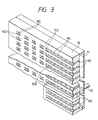
- each main vacuum suction plate 10 has a plurality of rows of groove sections 10B.
- Each row groove being discontinuous and extending in the direction of the width of the plate, nearly perpendicularly across the direction of feed of the thin stratified film 1B and consisting of groove sections 10B disposed at intervals in the direction of the feed thereof.
- Every groove section 10B has a prescribed length and is positioned at a prescribed interval so as to form a row extending in the direction of the width of the thin stratified film 1B, to appropriately cope with thin stratified films of different widths.
- the extreme end groove sections 10B are positioned so that the largest standard or expected width of thin film will just barely cover the extreme groove sections.
- the central groove section is positioned and has a length so that the smallest standard or expected width of thin film will just barely cover the entire central groove section.
- the remaining groove sections are positioned and sized accordingly to accommodate other intermediate standard or expected widths of thin films.
- a gas leak gap will not occur between the grooves 10B and each of thin stratified films of all applicable widths which are 195 mm, 245 mm, 295 mm, 330 mm, 400 mm, 495 mm and 600 mm, for example, when the film is sucked onto the main vacuum suction plate 10.
- a plurality of vacuum suction holes 10C for sucking the thin stratified film 1B onto the plate 10 are provided in the plate at the bottom of each of the grooves 10B, and, as shown in Fig. 3, are connected to a vacuum source such as a vacuum pump through a single suction chamber 51 and a single gas discharge pipe 52.
- the bottom of each groove 10B curves to the surface of the main vacuum suction plate 10 at both the ends of the groove, as shown in Fig. 4.
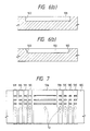
- each groove 10B may extend perpendicularly or obliquely to the surface of the main vacuum suction plate 10 at both the ends 10D of the groove, as shown in Fig. 6.
- each of the grooves 10B is shaped as an oblong, a semicircle, a triangle or the like, as shown in Figs. 5(a) - 5(c).
- the member 30 is located downstream with regard to the direction of the feed of the thin stratified film.
- the single suction chamber 51 and the single gas discharge pipe 52 may be divided into a plurality of suction chambers and a plurality of gas discharge pipes depending on the grooves 10B, if necessary.
- the single suction chamber 51 and the single gas discharge pipe 52 may be divided into a plurality of suction chambers 51A, 51B, 51C, 51D, 51E, 51F, 51G, 51H and 51I and a plurality of gas discharge pipes 52, as shown in Fig. 7. With such dividing, each of the thin stratified films 1B whose widths are 195 mm, 245 mm, 330 mm, 400 mm, 495 mm and 600 mm can be efficiently and securely sucked on the suction surface of the main vacuum suction plate 10.
- the thin film suction surface of a thin film feed member is provided with mutually discontinuous grooves at intervals depending on the widths of thin films, so that a gas leak is not made between each of the grooves and each of the thin films.
- the grooves in a row are distributed at intervals in the direction of the width of each of the thin films at positions depending on the widths of the films.
- a suction chamber for the thin film suction surface of the member may be divided into a prescribed number of suction chambers in the direction of the width of each of the thin films depending on the widths of the films so as to securely and efficiently suck each thin film on the suction surface of the member.
Landscapes
- Engineering & Computer Science (AREA)
- Mechanical Engineering (AREA)
- Robotics (AREA)
- Lining Or Joining Of Plastics Or The Like (AREA)
- Non-Metallic Protective Coatings For Printed Circuits (AREA)
- Adhesives Or Adhesive Processes (AREA)
Applications Claiming Priority (2)
| Application Number | Priority Date | Filing Date | Title |
|---|---|---|---|
| JP169328/88 | 1988-07-07 | ||
| JP16932888A JPH0218030A (ja) | 1988-07-07 | 1988-07-07 | 薄膜張付装置用薄膜供給部材 |
Publications (2)
| Publication Number | Publication Date |
|---|---|
| EP0350060A2 true EP0350060A2 (fr) | 1990-01-10 |
| EP0350060A3 EP0350060A3 (fr) | 1991-07-24 |
Family
ID=15884514
Family Applications (1)
| Application Number | Title | Priority Date | Filing Date |
|---|---|---|---|
| EP19890112471 Ceased EP0350060A3 (fr) | 1988-07-07 | 1989-07-07 | Elément d'alimentation d'un film mince pour une machine de revêtement par films minces |
Country Status (2)
| Country | Link |
|---|---|
| EP (1) | EP0350060A3 (fr) |
| JP (1) | JPH0218030A (fr) |
Cited By (1)
| Publication number | Priority date | Publication date | Assignee | Title |
|---|---|---|---|---|
| CN107696468A (zh) * | 2017-08-22 | 2018-02-16 | 东莞市蓉工自动化科技有限公司 | 一种用于电路板耦接的热熔胶膜自动贴合机 |
Family Cites Families (6)
| Publication number | Priority date | Publication date | Assignee | Title |
|---|---|---|---|---|
| US4100011A (en) * | 1975-08-04 | 1978-07-11 | Addressograph Multigraph Corp. | Production of laminated card with printed magnetically encodable stripe |
| US4464221A (en) * | 1983-01-28 | 1984-08-07 | Dynachem Corporation | Automatic laminator |
| US4659419A (en) * | 1983-05-11 | 1987-04-21 | Hakuto Co., Ltd. | Laminator for sticking film sheet on panel surface |
| DE3420429A1 (de) * | 1984-06-01 | 1985-12-05 | ELTI Apparatebau und Elektronik GmbH, 6106 Erzhausen | Verfahren zum laminieren eines films unter druck und waerme und vorrichtung zur durchfuehrung des verfahrens |
| EP0244817B1 (fr) * | 1986-05-07 | 1993-09-01 | Somar Corporation | Appareil pour la fabrication de stratifiés |
| US4909891A (en) * | 1986-11-06 | 1990-03-20 | Somar Corporation | Laminator |
-
1988
- 1988-07-07 JP JP16932888A patent/JPH0218030A/ja active Pending
-
1989
- 1989-07-07 EP EP19890112471 patent/EP0350060A3/fr not_active Ceased
Cited By (1)
| Publication number | Priority date | Publication date | Assignee | Title |
|---|---|---|---|---|
| CN107696468A (zh) * | 2017-08-22 | 2018-02-16 | 东莞市蓉工自动化科技有限公司 | 一种用于电路板耦接的热熔胶膜自动贴合机 |
Also Published As
| Publication number | Publication date |
|---|---|
| JPH0218030A (ja) | 1990-01-22 |
| EP0350060A3 (fr) | 1991-07-24 |
Similar Documents
| Publication | Publication Date | Title |
|---|---|---|
| KR101236687B1 (ko) | 부품 캐리어 및 제조 방법 | |
| CN113600720B (zh) | 柔性扁平线加工方法及冲切设备 | |
| US20030096531A1 (en) | Connector module organizer | |
| US4742615A (en) | Routing method and apparatus for cutting printed circuit boards | |
| EP0350060A2 (fr) | Elément d'alimentation d'un film mince pour une machine de revêtement par films minces | |
| US6269006B1 (en) | Card guide and method of guiding a circuit board | |
| JPH02185046A (ja) | 電子素子の自動処理装置 | |
| KR20010102048A (ko) | 박판금을 박판 스트립으로 절단하는 방법 및 상기 방법을수행하는 절단 장치 | |
| US7138579B2 (en) | Flexible grounding strip | |
| CN219107814U (zh) | 模切分板设备 | |
| CN219404425U (zh) | 一种pcb板加工用铜箔裁切设备 | |
| US6230394B1 (en) | X-Y table shield for component placement device | |
| JPS56108625A (en) | Linear motor conveyer | |
| JP2671483B2 (ja) | 基板分割装置 | |
| JP3134281B2 (ja) | 打ち抜き方法および打ち抜き装置 | |
| JP3010131B2 (ja) | 枚葉シート打抜き製造機 | |
| CN215301069U (zh) | 一种用于生产pcba线路板用的送料机构 | |
| CN214627517U (zh) | 线路板压平装置 | |
| CN219545906U (zh) | Pcb电路板收板架装置 | |
| JPH06106496A (ja) | 集塵ガイド装置 | |
| CA1283188C (fr) | Detecteur de bord de fuite | |
| KR100420875B1 (ko) | 벨트형 부품을 장착 장치에 전달하는 방법 및 장치 | |
| JPH10284882A (ja) | マウンタの部品供給方法 | |
| JPH0761579A (ja) | 搬送パレット及びその搬送装置 | |
| CN121751616A (zh) | 一种电路板自动化装配用元器件托盘 |
Legal Events
| Date | Code | Title | Description |
|---|---|---|---|
| PUAI | Public reference made under article 153(3) epc to a published international application that has entered the european phase |
Free format text: ORIGINAL CODE: 0009012 |
|
| AK | Designated contracting states |
Kind code of ref document: A2 Designated state(s): AT BE CH DE FR GB IT LI NL SE |
|
| PUAL | Search report despatched |
Free format text: ORIGINAL CODE: 0009013 |
|
| AK | Designated contracting states |
Kind code of ref document: A3 Designated state(s): AT BE CH DE FR GB IT LI NL SE |
|
| 17P | Request for examination filed |
Effective date: 19911129 |
|
| 17Q | First examination report despatched |
Effective date: 19930120 |
|
| STAA | Information on the status of an ep patent application or granted ep patent |
Free format text: STATUS: THE APPLICATION HAS BEEN REFUSED |
|
| 18R | Application refused |
Effective date: 19930710 |