EP0350090B1 - Futtertrog für Schweine und Ferkel - Google Patents
Futtertrog für Schweine und Ferkel Download PDFInfo
- Publication number
- EP0350090B1 EP0350090B1 EP89201617A EP89201617A EP0350090B1 EP 0350090 B1 EP0350090 B1 EP 0350090B1 EP 89201617 A EP89201617 A EP 89201617A EP 89201617 A EP89201617 A EP 89201617A EP 0350090 B1 EP0350090 B1 EP 0350090B1
- Authority
- EP
- European Patent Office
- Prior art keywords
- feed
- rotor
- closing element
- extension piece
- elevation
- Prior art date
- Legal status (The legal status is an assumption and is not a legal conclusion. Google has not performed a legal analysis and makes no representation as to the accuracy of the status listed.)
- Expired - Lifetime
Links
- 241000282887 Suidae Species 0.000 title claims abstract description 6
- 241001465754 Metazoa Species 0.000 claims abstract description 29
- 239000011391 polyester concrete Substances 0.000 claims abstract description 4
- 230000002093 peripheral effect Effects 0.000 claims description 10
- 239000011796 hollow space material Substances 0.000 claims description 7
- 230000033001 locomotion Effects 0.000 claims description 7
- 239000000463 material Substances 0.000 claims description 7
- 230000035622 drinking Effects 0.000 claims description 5
- 210000002445 nipple Anatomy 0.000 claims description 5
- 238000005192 partition Methods 0.000 claims description 5
- XLYOFNOQVPJJNP-UHFFFAOYSA-N water Substances O XLYOFNOQVPJJNP-UHFFFAOYSA-N 0.000 claims description 4
- 239000003651 drinking water Substances 0.000 claims description 3
- 235000020188 drinking water Nutrition 0.000 claims description 3
- 241000143973 Libytheinae Species 0.000 abstract description 3
- 210000004894 snout Anatomy 0.000 abstract description 3
- 101150006573 PAN1 gene Proteins 0.000 description 14
- 238000012423 maintenance Methods 0.000 description 2
- 238000004519 manufacturing process Methods 0.000 description 2
- 235000012054 meals Nutrition 0.000 description 2
- 230000001105 regulatory effect Effects 0.000 description 2
- 230000000284 resting effect Effects 0.000 description 2
- 238000010276 construction Methods 0.000 description 1
- 238000007599 discharging Methods 0.000 description 1
- 230000000694 effects Effects 0.000 description 1
- 239000008187 granular material Substances 0.000 description 1
- 238000000034 method Methods 0.000 description 1
- 239000004033 plastic Substances 0.000 description 1
- 238000000926 separation method Methods 0.000 description 1
- 229910001220 stainless steel Inorganic materials 0.000 description 1
- 239000010935 stainless steel Substances 0.000 description 1
- 238000003756 stirring Methods 0.000 description 1
Images



Classifications
-
- A—HUMAN NECESSITIES
- A01—AGRICULTURE; FORESTRY; ANIMAL HUSBANDRY; HUNTING; TRAPPING; FISHING
- A01K—ANIMAL HUSBANDRY; AVICULTURE; APICULTURE; PISCICULTURE; FISHING; REARING OR BREEDING ANIMALS, NOT OTHERWISE PROVIDED FOR; NEW BREEDS OF ANIMALS
- A01K5/00—Feeding devices for stock or game ; Feeding wagons; Feeding stacks
- A01K5/02—Automatic devices
- A01K5/0225—Gravity replenishment from a reserve, e.g. a hopper
-
- A—HUMAN NECESSITIES
- A01—AGRICULTURE; FORESTRY; ANIMAL HUSBANDRY; HUNTING; TRAPPING; FISHING
- A01K—ANIMAL HUSBANDRY; AVICULTURE; APICULTURE; PISCICULTURE; FISHING; REARING OR BREEDING ANIMALS, NOT OTHERWISE PROVIDED FOR; NEW BREEDS OF ANIMALS
- A01K5/00—Feeding devices for stock or game ; Feeding wagons; Feeding stacks
- A01K5/02—Automatic devices
Definitions
- the invention relates in general to a device for feeding animals, in particular pigs and piglets.
- FR-A-2 563 078 describes such a device which comprises a feed pan, a superstructure fixed on the feed pan and feed supply means for supplying feed to the pan.
- the round feed pan is provided with a raised peripheral wall and in the center with an elevation in the form of a truncated cone which is approximately the same height as the raised peripheral wall.
- the superstructure comprises an extension piece situated coaxially above the elevation in the feed pan and is essentially the shape of a largely hollow, round tower which is open at the bottom.
- the extension piece which serves as a feed container, rests via a grid of curved bars extending in the radial direction on the peripheral wall of the feed pan. Between the bottom edge of the extension piece and the elevation in the feed pan there is an annular feed fall-out aperture.
- the feed supply means are located mainly inside the extension piece and comprise a funnel-shaped element which is adjustable in height and which opens coaxially above the elevation in the feed pan at short distance from a rotatable disc situated coaxially between the funnel-shaped element and the elevation and having vanes extending radially through the feed fall-out aperture.
- a rotatable disc situated coaxially between the funnel-shaped element and the elevation and having vanes extending radially through the feed fall-out aperture.
- the disc can be rotated by the feeding animals. Through this action feed falling through the funnel shaped element is distributed by the rotating disc into the feed pan.
- the quantity of feed falling into the feed pan can be regulated by adjusting the height of the funnel-shaped element.
- the known device has a number of disadvantages.
- the feed supply to the feed pan cannot be regulated accurately enough such that on the one hand the animals get always enough feed and on the other hand it is prevented that too much feed falls into the feed pan and feed is spilt.
- This is, among other things, due to the fact that the opening in the bottom of the funnel-shaped element cannot be closed completely, the adjustment of the height of the funnel-shaped element is difficult, particularly when the extension piece is filled with feed, the rotor can be turned inadvertently by the animals while they are eating, and the rotor can get stuck by caking of the feed.
- both the production and the maintenance costs of the known device will be high.
- EP-A-0 076 663 discloses a device for feeding animals which comprises feed supply means comprising feed supply means comprising a closing element situated coaxially between feed supply pipe and a rotor, said closing element being moveable in the axial direction between an upper position in which it rests against the bottom end of the feed supply pipe and closes said pipe, while it lies free from the rotor, and a lower position at distance from the bottom end of the feed supply channel, in which the closing element opens the feed supply pipe.
- the closing element is however not rotatable about its axis in the sense of the present invention and in its lower position it is not coupled to the rotor, so that it is not rotatable together with the rotor.
- the superstructure of the device for feeding animals disclosed in FR-A-0 076 663 has no extension piece in the form of a largely hollow, round tower.
- the object of the present invention is to provide a device for feeding animals with which the correct amount of feed is always present in the feed pan during feeding.
- a device for feeding animals comprising a feed pan, a superstructure fixed on the feed pan and feed supply means for supplying feed to the feed pan, the feed pan being provided with a raised peripheral wall and in the center with an elevation in the form of a truncated cone, the superstructure comprising an extension piece situated coaxially above the elevation and being essentially the shape of a largely hollow, round tower which is open at the bottom, such that between the bottom edge of the extension piece and the elevation there is an annular feed fall-out aperture, and the feed supply means being located mainly inside the extension piece and comprising a feed supply channel which opens coaxially above the elevation and a rotor situated coaxially between the feed supply channel and the elevation and having vanes extending radially through the feed fall-out aperture, which device is characterized in that the feed supply means further comprise a closing element situated coaxially between the feed supply channel and the rotor, said closing element being rotatable about its axi
- the feed supply channel can be closed completely in which situation rotation of the rotor has no effect on the feed supply. During feeding a regular flow of feed into the feed pan is achieved.
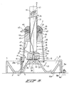
- the device shown in the drawings for the feeding of animals, in particular pigs and piglets, comprises the following two main parts: a feed pan 1 and a superstructure 2 which is fixed on the feed pan 1 and bears means for supplying feed to the feed pan.
- the feed pan 1 is round in shape and is provided with a bottom 3, a raised peripheral wall 4, and an elevation 5 in the shape of a truncated cone disposed in the center.
- the feed pan 1 is thus essentially the shape of an annular through 6, on the bottom 7 of which the feed comes to rest.
- the raised peripheral wall 4 may be at a different angle with respect to the bottom 3 as is shown in Figures 2 and 3.
- the feed pan 1 can be fixed to a sty floor by means of a number of clamping bolts 8 and clamping brackets 9 which mate with them and engage over a projecting flange 10 formed on the bottom edge of the pan, as shown in Figure 2, or by means of a number of clamping bolts 8a and clamping brackets 9a which engage over the top edge of the peripheral wall 4 of the pan, as shown in Figure 3.
- Rubber pads 8b can be provided near the bolts 8a between the lower outer edge of the feed pan 1 and the sty floor, indicated by 10a in Figure 3, in order to be able to fix the feed pan 1 properly, also when the sty floor 10a is uneven.
- the superstructure 2 comprises an extension piece 11 situated centrally above the pan.
- This extension piece is essentially the shape of a round tower which is largely hollow and is open at the bottom.
- the diameter of the extension piece 11 at the bottom is approximately the same as the diameter of the elevation 5 in the feed pan 1 at the bottom 3.
- the extension piece 11 rests with its bottom side near the bottom edge 12 on a number of legs 13 extending upwards from the bottom 3 of the feed pan.
- Each leg 13 is fixed to the extension piece by a bolt 14 by means of a boss 15 projecting from the outside wall of the extension piece, and is connected to the floor of the feed pan 1 by a bolt 16.
- the extension piece is thereby easy to fit and remove.
- the extension piece is resting on four legs 13.
- the height of the legs is such that the bottom edge of the extension piece lies at approximately the same height as the top side of the raised edge 4 of the pan 1 and the top side of the elevation 5.
- This feed supply pipe 18 is disposed coaxially in the top part of the extension piece 11 and opens into the hollow space 19 in the extension piece 11 some distance away from the top side of the elevation 5 in the feed pan 1.
- the feed supply pipe 18 can be closed off at the bottom side by means of a closing element 20 in the form of a thick round disc.
- the closing element is rotatable about its axis and can be moved in the axial direction.
- the closing element is provided in the middle with a slightly conical bore 21 extending from the bottom side towards the top and beared in this bore on a pin 22 which extends coaxially upwards from the top side of the elevation 5 in the feed pan 1 and is fixed in the elevation 5.
- the closing element 20 is rotatable about said pin 22 and slidable in the axial direction.
- a short pin 25a is fitted in the closing element on the top side at the bore 21.
- the closing element 20 is provided on the bottom side with projecting bosses 23. On the top side the closing element is provided with an elevation 24, which is triangular viewed from the top.
- the closing element 20 When the feed supply is closed the closing element 20 is pulled against the bottom end 26 of the feed supply pipe 18 by means of the wire 25, thus closing the pipe 18.
- the closing element 20 When the feed supply is open, the closing element 20 lies a distance away from the feed supply pipe 18, so that feed can flow out of the pipe 18. In this position the closing element serves as a feed distribution element, the closing element being rotated about its axis.
- the triangular elevation 24 provides an effective sideward movement of the feed.
- the elevation need not be triangular. It may also have other shapes, for example square or star-shaped. Important is that it provides a sideward movement of the feed.
- a rotor 27 resting on the top side of the elevation 5 and being rotatable over this elevation comprising a number of control elements connected to each other and having the form of vertical vanes 28 extending radially through the feed fall-out aperture.
- These vanes 28 are of such a shape that during the rotation of the rotor 27 they move closely along the external surface of the elevation 5, the bottom edge 12 of the extension piece 11 and the legs 13, thus preventing caking of feed.
- the rotor is provided with three of such vanes 28.
- the rotor can be made freely rotatable through 360°. It is, however, also possible to make the rotor rotatable through only a limited angle between 0° and 360°.
- the animals can set the vanes 28 of the rotor 27 in motion with their snouts, thus causing the rotor to rotate.
- the rotor is provided at the top side with carrier ribs 29 which can drive the projecting bosses 23 at the bottom side of the closing element 20, which during feeding is in the position shown in Figures 2 and 3, the closing element 20, also functioning as a feed distribution element, is rotated during the rotation of the rotor 27, and the feed supplied through the pipe 18 is distributed over the periphery and conveyed to the feed fall-out aperture 17.
- the rotor 27 shown in Figure 3 is provided with a peripheral ring 28a connected to the vanes 28.
- this ring 28a is to enable the feeding animal or animals to rotate the rotor 27 in any position of the rotor, also when a vane 28 lies just behind a leg 13. To prevent the ring 28a from being pushed downwards by the snouts of the feeding animals by which the rotor 27 may be damaged, the ring 28a is mounted such that it lies closely below the bottom edge 12 of the extension piece 11.
- the rotor is limited in its downward movement in the axial direction by means of a stop 30 on the pin 22.
- the wire 25 serves as a stirring element for the feed present in the pipe 18.
- the feed supply pipe 18 is made up of two pipes 31 and 32 sliding telescopically into each other.
- the outer pipe 31 is fixed coaxially in the top part of the extension piece 11, and the sliding inner pipe 32 opens into the hollow space 19 in the extension piece 11.
- the position of the inner pipe 32 relative to the outer pipe 31 is adjustable due to the fact that the inner pipe 32 is provided with a clamping bolt 33 which can move through a slanting slot 34 in the outer pipe 31.
- the height of the end 26 of the inner pipe can be adjusted by turning the inner pipe 32 relative to the outer pipe 31.
- the inner pipe 32 is shown approximately in the central position.
- the top end position of the bottom end 26 of the inner pipe 32 is indicated by a dotted line 35.
- This design of the feed supply pipe means that in the open position of the feed supply the size of the feed supply aperture can be set. This setting is not critical and in fact serves only for the adjustment of the feed supply aperture to the type of feed (meal or granules).
- the extension piece 11 in the embodiment shown is made up of a central housing 36 in which the hollow space 19 is formed and which rests on the legs 13, and an annular part 37 fixed on the top of the housing and containing a drinking water supply system.
- the annular part 37 is fixed to the housing 36 by means of bolts 38, the centering taking place by means of a centering edge 39.
- the shape of the annular part 37 is such that it would be difficult for the animals to stand with their feet on it.
- the drinking water supply system has a number of drinking nipples 40 (in this case four) disposed on the side of the annular part 37, a water supply pipe 41 disposed on the top side of the annular part 37, and a connecting channel 42 inside the annular part 37 between the water supply pipe 41 and the drinking nipples 40.
- FIGS 2 and 3 show that the outer pipe 31 of the feed supply pipe 18 is clamped in the top part of the extension piece 11 by means of a rubber ring 43 present between the housing 36 and the annular part 37.
- the pan 1, the housing 36, the annular part 37 and the closing element 20 are preferably made of a cast or moulded material. There is a special preference here for polyester concrete, which is easy to cast and is also cheap.
- the feed supply pipe is preferably made of plastic material.
- annular part 37 is of cast material, during its production inserts 44 for the connection of the drinking nipples 40 and the water supply pipe 41 and a connecting pipe 45 between the inserts 44 can be cast in.
- the wall of the housing 36 can be provided with a number of vent holes 46 distributed over the periphery, and each disposed between two drinking nipples. These vent holes are for discharging the moisture-laden breath of the feeding animals, and thereby prevent the feed from caking and mould from forming.
- the top side of the hollow space 19 of the housing 36 can be provided with a number of ribs 47 which ensure that when several housings 36 are stacked in each other they are kept some distance apart, which prevents the slightly conical inner wall of a housing 36 from becoming jammed on the also conical outer wall of another housing 36 projecting into the hollow space 19.
- the bottom edge 48 of the ribs 47 rests here on the top edge 49 of the housing 36.
- the feeding device described can be set up at any point in a pen, in such a way that the animals present in the pen can reach the feeding device on all sides. It is, however, possible to set up the device at the partition 50 between two pens 51 and 52, as shown in Figure 4, or even at the point of intersection of two partitions, so that animals from two or four neighboring, but separate pens can feed from one feeding device.
- the feeding device according to the invention has the following advantages over the known device for feeding animals:
Landscapes
- Life Sciences & Earth Sciences (AREA)
- Environmental Sciences (AREA)
- Birds (AREA)
- Animal Husbandry (AREA)
- Biodiversity & Conservation Biology (AREA)
- Feeding And Watering For Cattle Raising And Animal Husbandry (AREA)
- Fodder In General (AREA)
- Feed For Specific Animals (AREA)
Claims (11)
- Vorrichtung zum Füttern von Tieren, insbesondere Schweinen und Ferkeln, mit einem Futtertrog (1), einem auf dem Futtertrog befestigten Aufbau (2) und Futter-Zufuhrmitteln zum Zuführen von Futter zu dem Futtertrog, wobei der Futtertrog (1) mit einer erhöhten Umfangswand (4) und in der Mitte mit einer Erhebung (5) in der Form eines Kegelstumpfs versehen ist, der Aufbau (2) ein Verlängerungsstück (11) aufweist, das koaxial über der Erhebung (5) angebracht ist und im wesentlichen die Form eines weitgehend hohlen, runden Turmes hat, der an seinem Boden offen ist, so daß zwischen dem unteren Rand (12) des Verlängerungsstücks (11) und der Erhebung (5) eine ringförmige Futter-Auslaßöffnung (17) besteht, und wobei die Futter-Zufuhrmittel in der Hauptsache im Inneren des Verlängerungsstücks (11) angeordnet sind und einen sich koaxial über der Erhebung (5) öffnenden Futter-Zufuhrkanal (18) und einen Rotor (27) aufweisen, der koaxial zwischen dem Futter-Zufuhrkanal (18) und der Erhebung (5) angeordnet ist und Flügel (28) aufweist, die sich radial durch die Futter-Auslaßöffnung (17) erstrecken, dadurch gekennzeichnet, daß die Futter-Zufuhrmittel weiterhin ein Verschlußelement (20) aufweisen, das sich koaxial zwischen dem Futter-Zufuhrkanal (18) und dem Rotor (27) befindet, welches Verschlußelement (20) um seine Achse drehbar ist und in der Axialrichtung beweglich ist zwischen einer oberen Position, in der es am unteren Ende (26) des Futter-Zufuhrkanals (18) anliegt und diesen Kanal verschließt, während es frei von dem Rotor (27) abliegt, und einer unteren Position in Abstand zu dem unteren Ende (26) des Futter-Zufuhrkanals (18), in der das Verschlußelement (20) den Futter-Zufuhrkanal (18) öffnet und koaxial mit dem Rotor (27) gekoppelt ist, so daß das Verschlußelement (20) zusammen mit dem Rotor (27) drehbar ist und als rotierendes Futterverteilungselement fungieren kann.
- Vorrichtung nach Anspruch 1, dadurch gekennzeichnet, daß das Verschlußelement (20) die Form einer dicken runden Scheibe hat, die in der Mitte mit einer Bohrung (21) versehen ist, die sich von der Unterseite nach oben erstreckt und in welche ein Stift (22) von der Oberseite der Erhebung (5) des Futtertroges aus koaxial nach oben hineinragt, so daß das Verschlußelement (20) um den Stift drehbar und längs des Stiftes verschiebbar ist, und daß das Verschlußelement (20) an der Unterseite mit vorspringenden Buckeln (23) versehen ist, die mit auf dem Rotor (27) angeordneten Tragelementen (29) zum Drehen des Verschlußelements (20) zusammenwirken können.
- Vorrichtung nach Anspruch 1 oder 2, dadurch gekennzeichnet, daß das Verschlußelement (20) auf der Oberseite mit einer Erhebung (24) versehen ist, die eine Seitwärtsbewegung des aus dem Futter-Zufuhrkanal (18) austretenden Futters bewirkt und die in der Draufsicht vorzugsweise dreieckig ist.
- Vorrichtung nach Anspruch 1, dadurch gekennzeichnet, daß der Futter-Zufuhrkanal aus einem Futter-Zufuhrrohr (18) besteht, das aus zwei teleskopisch ineinanderschiebbaren Rohren (31, 32) aufgebaut ist, von denen das äußere Rohr (31) koaxial in einem oberen Teil des Verlängerungsstücks (11) befestigt ist und das innere Rohr (32) mit seinem unteren Ende (26) in den Hohlraum (19) in dem Verlängerungsstück (11) mündet, wobei die Position des inneren Rohres (32) relativ zu dem äußeren Rohr (31) und somit die Größe der Öffnung zwischen dem unteren Ende (26) des inneres Rohres (32) und dem Verschlußelement (20) einstellbar ist, wenn sich das Verschlußelement (20) in seiner unteren Position befindet.
- Vorrichtung nach Anspruch 1, dadurch gekennzeichnet, daß der Rotor (27) auf der Oberseite der Erhebung (5) aufliegt und die Flügel (28) des Rotors (27) eine solche Form haben, daß sich die Flügel während der Drehung des Rotors dicht an der äußeren Oberfläche der Erhebung (5), dem unteren Rand (12) des Verlängerungsstücks (11) entlang bewegen und so das Festsetzen des Futters verhindern.
- Vorrichtung nach Anspruch 5, dadurch gekennzeichnet, daß der Rotor (27) mit einem Umfangs-Ring (28a) versehen ist, der mit den Flügeln (28) verbunden ist, wobei der Ring (28a) so an dem Rotor (27) montiert ist, daß er dicht unter dem unteren Rand (12) des Verlängerungsstücks (11) liegt.
- Vorrichtung nach Anspruch 1, dadurch gekennzeichnet, daß die äußere Wand des Verlängerungsstücks (11) mit einer Anzahl von Lüftungsöffnungen (46) versehen ist.
- Vorrichtung nach Anspruch 1, dadurch gekennzeichnet, daß das Verlängerungsstück (11) mit der Bodenseite in der Nähe des unteren Randes (12) auf einer Anzahl von Füßen (13) ruht, die sich vom Boden (3) des Futtertroges (1) nach oben erstrecken, und daß die radialen Abmessungen der Flügel (28) des Rotors (27) so gewählt sind, daß die Flügel sich während der Drehung des Rotors dicht an den Füßen (13) vorbeibewegen.
- Vorrichtung Anspruch 8, dadurch gekennzeichnet, daß das Verlängerungsstück (11) aufgebaut ist aus einem zentralen Gehäuse (26), in dem ein Hohlraum (19) ausgebildet ist und das auf den vom Boden (3) des Futtertroges (1) ausgehenden Füßen (13) ruht, und einem ringförmigen Teil (37), das auf der Oberseite des Gehäuses befestigt ist und ein Trinkwasser-Zufuhrsystem enthält, wobei das ringförmige Teil (37) vorzugsweise aus gegossenem oder geformtem Material hergestellt ist und in das eine Anzahl von Einsätzen (44) für die Verbindung von Trinknippeln (40) und einem Wasser-Zufuhrrohr (41) sowie ein Verbindungsrohr zwischen den Einsätzen (44) eingegossen oder eingeformt sind.
- Vorrichtung nach Anspruch 1, dadurch gekennzeichnet, daß der Futtertrog (1) und das Verlängerungsstück (11) im wesentlichen aus einem gegossenen oder geformten Material, vorzugsweise Polyesterbeton bestehen.
- Stall mit wenigstens einer Vorrichtung zum Füttern von Tieren nach einem oder mehreren der Ansprüche 1 bis 10, wobei die mindestens eine Füttervorrichtung in einem Verschlag (51, 52) an der Trennwand (50) zwischen zwei Verschlägen (51, 52) oder am Schnittpunkt zweier solcher Trennwände angeordnet ist.
Priority Applications (1)
| Application Number | Priority Date | Filing Date | Title |
|---|---|---|---|
| AT8989201617T ATE104508T1 (de) | 1988-07-04 | 1989-06-19 | Futtertrog fuer schweine und ferkel. |
Applications Claiming Priority (2)
| Application Number | Priority Date | Filing Date | Title |
|---|---|---|---|
| NL8801692 | 1988-07-04 | ||
| NL8801692A NL8801692A (nl) | 1988-07-04 | 1988-07-04 | Voederpan voor varkens en biggen. |
Publications (2)
| Publication Number | Publication Date |
|---|---|
| EP0350090A1 EP0350090A1 (de) | 1990-01-10 |
| EP0350090B1 true EP0350090B1 (de) | 1994-04-20 |
Family
ID=19852567
Family Applications (1)
| Application Number | Title | Priority Date | Filing Date |
|---|---|---|---|
| EP89201617A Expired - Lifetime EP0350090B1 (de) | 1988-07-04 | 1989-06-19 | Futtertrog für Schweine und Ferkel |
Country Status (11)
| Country | Link |
|---|---|
| US (1) | US4947798A (de) |
| EP (1) | EP0350090B1 (de) |
| KR (1) | KR900001292A (de) |
| AT (1) | ATE104508T1 (de) |
| CA (1) | CA1315619C (de) |
| DE (1) | DE68914732T2 (de) |
| DK (1) | DK332389A (de) |
| ES (1) | ES2055009T3 (de) |
| NL (1) | NL8801692A (de) |
| PT (1) | PT91044B (de) |
| ZA (1) | ZA894798B (de) |
Families Citing this family (19)
| Publication number | Priority date | Publication date | Assignee | Title |
|---|---|---|---|---|
| DK2592D0 (da) * | 1992-01-08 | 1992-01-08 | Hans Rasmussen | Fodringsapparat |
| US7530328B2 (en) | 1997-05-09 | 2009-05-12 | Ctb Ip, Inc. | Indexed feed dispensing mechanism |
| US6526913B2 (en) * | 1997-05-09 | 2003-03-04 | Staco, Inc. | Indexed feed dispensing mechanism |
| US5921200A (en) | 1997-05-09 | 1999-07-13 | Bondarenko; Paul J. | Animal feeder with dispensing mechanism and dust cover |
| ES2167266B1 (es) * | 2000-09-15 | 2003-05-16 | Tigsa | Conjunto para la alimentacion de animales. |
| JP2002191249A (ja) * | 2000-12-25 | 2002-07-09 | Fujii Shokai:Kk | 養豚用給餌器 |
| US7988024B2 (en) * | 2002-02-14 | 2011-08-02 | Beachpacker, Llc | Beach equipment carrying apparatus |
| KR100470454B1 (ko) * | 2002-05-14 | 2005-02-05 | 대한민국 | 돼지 사료공급을 위한 자동조절급이기 |
| US6655317B1 (en) | 2002-10-31 | 2003-12-02 | Val Products, Inc. | Adjustable poultry feeder |
| US6845735B1 (en) * | 2002-11-15 | 2005-01-25 | Doskocil Manufacturing Company, Inc. | Pet feeder |
| US20100224132A1 (en) | 2009-03-06 | 2010-09-09 | Andrew Gauker | Top-fill hummingbird feeder with float valve base closure mechanism |
| US8459204B2 (en) | 2010-06-07 | 2013-06-11 | Roy Lato | Livestock feeder system |
| DE202012010237U1 (de) | 2012-10-26 | 2014-01-29 | Big Dutchman Pig Equipment Gmbh | Höhenverstellbarer Futtertrog |
| US9089111B2 (en) | 2013-03-05 | 2015-07-28 | Woodstream Corporation | Oriole jelly birdfeeder |
| CN104012422B (zh) * | 2014-04-18 | 2016-03-16 | 湖南伟业生物科技有限公司 | 一种自动饲喂器 |
| KR101800778B1 (ko) | 2015-08-27 | 2017-11-23 | 안광덕 | 사료급이기 틸팅장치 |
| US11647734B2 (en) | 2018-09-07 | 2023-05-16 | Butterfly Concepts Llc | Variable dimension poultry feeder |
| US11076580B2 (en) | 2018-09-07 | 2021-08-03 | Butterfly Concepts Llc | Variable dimension poultry feeder |
| EP3984357A1 (de) * | 2020-03-11 | 2022-04-20 | Lyschick & Müller Entwicklungs GbR | Futterabgabeanlage zur versorgung von tieren mit tiernahrung |
Family Cites Families (11)
| Publication number | Priority date | Publication date | Assignee | Title |
|---|---|---|---|---|
| GB203561A (en) * | 1922-10-18 | 1923-09-13 | Samuel Arthur Peto | Improvements relating to feeding appliances for pigs and/or other animals |
| US2808029A (en) * | 1956-11-30 | 1957-10-01 | Petrus J Geerlings | Hog feeder |
| US2884899A (en) * | 1957-04-25 | 1959-05-05 | Jackes Evans Mfg Company | Feeding device for poultry |
| US3911868A (en) * | 1973-07-12 | 1975-10-14 | Chore Time Equipment | Poultry feeder |
| US3971340A (en) * | 1974-08-19 | 1976-07-27 | U.S. Industries, Inc. | Limit and control feeder for animals |
| US4401057A (en) * | 1981-10-05 | 1983-08-30 | Chore-Time Equipment, Inc. | Hog feeder |
| US4433641A (en) * | 1982-08-18 | 1984-02-28 | Waite Dwaine C | Baby pig feeder |
| IT1175175B (it) * | 1983-07-13 | 1987-07-01 | Ska Spa | Mangiatoia con regolazione di livello del mangime per volatili d'allevamento, in particolare per tacchini |
| FR2563078B1 (fr) * | 1984-04-20 | 1987-02-06 | Nusse Bernard | Nourrisseur automatique autocontrole |
| US4841912A (en) * | 1987-10-19 | 1989-06-27 | Oswald Robert L | Animal feeder |
| US4834026A (en) * | 1988-02-01 | 1989-05-30 | Ctb, Inc. | Poultry feeder assembly |
-
1988
- 1988-07-04 NL NL8801692A patent/NL8801692A/nl not_active Application Discontinuation
-
1989
- 1989-06-19 AT AT8989201617T patent/ATE104508T1/de not_active IP Right Cessation
- 1989-06-19 DE DE68914732T patent/DE68914732T2/de not_active Expired - Fee Related
- 1989-06-19 ES ES89201617T patent/ES2055009T3/es not_active Expired - Lifetime
- 1989-06-19 EP EP89201617A patent/EP0350090B1/de not_active Expired - Lifetime
- 1989-06-23 ZA ZA894798A patent/ZA894798B/xx unknown
- 1989-06-23 US US07/370,639 patent/US4947798A/en not_active Expired - Fee Related
- 1989-06-28 CA CA000604172A patent/CA1315619C/en not_active Expired - Fee Related
- 1989-07-03 PT PT91044A patent/PT91044B/pt not_active IP Right Cessation
- 1989-07-04 DK DK332389A patent/DK332389A/da not_active Application Discontinuation
- 1989-07-04 KR KR1019890009488A patent/KR900001292A/ko not_active Ceased
Also Published As
| Publication number | Publication date |
|---|---|
| DE68914732T2 (de) | 1994-09-29 |
| ATE104508T1 (de) | 1994-05-15 |
| PT91044A (pt) | 1990-02-08 |
| US4947798A (en) | 1990-08-14 |
| NL8801692A (nl) | 1990-02-01 |
| CA1315619C (en) | 1993-04-06 |
| ZA894798B (en) | 1990-03-28 |
| DK332389D0 (da) | 1989-07-04 |
| KR900001292A (ko) | 1990-02-27 |
| DK332389A (da) | 1990-01-05 |
| PT91044B (pt) | 1994-07-29 |
| EP0350090A1 (de) | 1990-01-10 |
| DE68914732D1 (de) | 1994-05-26 |
| ES2055009T3 (es) | 1994-08-16 |
Similar Documents
| Publication | Publication Date | Title |
|---|---|---|
| US4947798A (en) | Feed pan for pigs and piglets | |
| US4889078A (en) | Hog feeder | |
| KR100798563B1 (ko) | 자동사료공급장치 | |
| US5435267A (en) | Livestock feeder | |
| EP0379791B1 (de) | Fütterungsanlage | |
| CA2952227C (en) | Rotary livestock feeder with gravity flow feed openings | |
| US7302912B2 (en) | Discharge unit for a game feeder | |
| US4401057A (en) | Hog feeder | |
| US2808029A (en) | Hog feeder | |
| US7730851B2 (en) | Animal feeder device | |
| US6626128B2 (en) | Feed doser and regulator for troughs | |
| RU2145162C1 (ru) | Кормораздатчик, в частности, для свиней | |
| US20130139757A1 (en) | Poultry feeding device | |
| EP3154336B1 (de) | Rotierende viehfütterungsvorrichtung mit schwerkraftzuflussöffnungen | |
| JPH0339020A (ja) | 豚および子豚用給餌装置 | |
| SU1033101A1 (ru) | Устройство дл раздачи корма рыбам | |
| ITPG970016A1 (it) | Mangiatoia automatica per alimentazione ed abbeveraggio animali, in grado di erogare l'alimento in modo razionato o continuo |
Legal Events
| Date | Code | Title | Description |
|---|---|---|---|
| PUAI | Public reference made under article 153(3) epc to a published international application that has entered the european phase |
Free format text: ORIGINAL CODE: 0009012 |
|
| AK | Designated contracting states |
Kind code of ref document: A1 Designated state(s): AT BE CH DE ES FR GB GR IT LI LU NL SE |
|
| 17P | Request for examination filed |
Effective date: 19900706 |
|
| RAP1 | Party data changed (applicant data changed or rights of an application transferred) |
Owner name: ROXELL N.V. |
|
| 17Q | First examination report despatched |
Effective date: 19911016 |
|
| GRAA | (expected) grant |
Free format text: ORIGINAL CODE: 0009210 |
|
| AK | Designated contracting states |
Kind code of ref document: B1 Designated state(s): AT BE CH DE ES FR GB GR IT LI LU NL SE |
|
| PG25 | Lapsed in a contracting state [announced via postgrant information from national office to epo] |
Ref country code: LI Effective date: 19940420 Ref country code: CH Effective date: 19940420 Ref country code: AT Effective date: 19940420 |
|
| REF | Corresponds to: |
Ref document number: 104508 Country of ref document: AT Date of ref document: 19940515 Kind code of ref document: T |
|
| REF | Corresponds to: |
Ref document number: 68914732 Country of ref document: DE Date of ref document: 19940526 |
|
| PG25 | Lapsed in a contracting state [announced via postgrant information from national office to epo] |
Ref country code: LU Free format text: LAPSE BECAUSE OF NON-PAYMENT OF DUE FEES Effective date: 19940630 |
|
| ITF | It: translation for a ep patent filed | ||
| ET | Fr: translation filed | ||
| REG | Reference to a national code |
Ref country code: CH Ref legal event code: PL |
|
| REG | Reference to a national code |
Ref country code: ES Ref legal event code: FG2A Ref document number: 2055009 Country of ref document: ES Kind code of ref document: T3 |
|
| REG | Reference to a national code |
Ref country code: GR Ref legal event code: FG4A Free format text: 3012171 |
|
| EAL | Se: european patent in force in sweden |
Ref document number: 89201617.1 |
|
| PLBE | No opposition filed within time limit |
Free format text: ORIGINAL CODE: 0009261 |
|
| STAA | Information on the status of an ep patent application or granted ep patent |
Free format text: STATUS: NO OPPOSITION FILED WITHIN TIME LIMIT |
|
| 26N | No opposition filed | ||
| PGFP | Annual fee paid to national office [announced via postgrant information from national office to epo] |
Ref country code: GR Payment date: 19960326 Year of fee payment: 8 |
|
| PGFP | Annual fee paid to national office [announced via postgrant information from national office to epo] |
Ref country code: SE Payment date: 19960329 Year of fee payment: 8 Ref country code: FR Payment date: 19960329 Year of fee payment: 8 |
|
| PGFP | Annual fee paid to national office [announced via postgrant information from national office to epo] |
Ref country code: BE Payment date: 19960412 Year of fee payment: 8 |
|
| PGFP | Annual fee paid to national office [announced via postgrant information from national office to epo] |
Ref country code: GB Payment date: 19960605 Year of fee payment: 8 |
|
| PGFP | Annual fee paid to national office [announced via postgrant information from national office to epo] |
Ref country code: ES Payment date: 19960612 Year of fee payment: 8 |
|
| PGFP | Annual fee paid to national office [announced via postgrant information from national office to epo] |
Ref country code: DE Payment date: 19960626 Year of fee payment: 8 |
|
| PGFP | Annual fee paid to national office [announced via postgrant information from national office to epo] |
Ref country code: NL Payment date: 19960630 Year of fee payment: 8 |
|
| PG25 | Lapsed in a contracting state [announced via postgrant information from national office to epo] |
Ref country code: GB Free format text: LAPSE BECAUSE OF NON-PAYMENT OF DUE FEES Effective date: 19970619 |
|
| PG25 | Lapsed in a contracting state [announced via postgrant information from national office to epo] |
Ref country code: SE Effective date: 19970620 Ref country code: ES Free format text: LAPSE BECAUSE OF NON-PAYMENT OF DUE FEES Effective date: 19970620 |
|
| PG25 | Lapsed in a contracting state [announced via postgrant information from national office to epo] |
Ref country code: GR Free format text: LAPSE BECAUSE OF NON-PAYMENT OF DUE FEES Effective date: 19970630 Ref country code: BE Effective date: 19970630 |
|
| BERE | Be: lapsed |
Owner name: ROXELL N.V. Effective date: 19970630 |
|
| PG25 | Lapsed in a contracting state [announced via postgrant information from national office to epo] |
Ref country code: NL Effective date: 19980101 |
|
| GBPC | Gb: european patent ceased through non-payment of renewal fee |
Effective date: 19970619 |
|
| PG25 | Lapsed in a contracting state [announced via postgrant information from national office to epo] |
Ref country code: FR Free format text: LAPSE BECAUSE OF NON-PAYMENT OF DUE FEES Effective date: 19980227 |
|
| EUG | Se: european patent has lapsed |
Ref document number: 89201617.1 |
|
| NLV4 | Nl: lapsed or anulled due to non-payment of the annual fee |
Effective date: 19980101 |
|
| PG25 | Lapsed in a contracting state [announced via postgrant information from national office to epo] |
Ref country code: DE Free format text: LAPSE BECAUSE OF NON-PAYMENT OF DUE FEES Effective date: 19980303 |
|
| REG | Reference to a national code |
Ref country code: FR Ref legal event code: ST |
|
| REG | Reference to a national code |
Ref country code: FR Ref legal event code: ST |
|
| REG | Reference to a national code |
Ref country code: ES Ref legal event code: FD2A Effective date: 20000403 |
|
| PG25 | Lapsed in a contracting state [announced via postgrant information from national office to epo] |
Ref country code: IT Free format text: LAPSE BECAUSE OF NON-PAYMENT OF DUE FEES Effective date: 20050619 |