EP0350190A2 - Cylindre pneumatique - Google Patents
Cylindre pneumatique Download PDFInfo
- Publication number
- EP0350190A2 EP0350190A2 EP89306464A EP89306464A EP0350190A2 EP 0350190 A2 EP0350190 A2 EP 0350190A2 EP 89306464 A EP89306464 A EP 89306464A EP 89306464 A EP89306464 A EP 89306464A EP 0350190 A2 EP0350190 A2 EP 0350190A2
- Authority
- EP
- European Patent Office
- Prior art keywords
- piston
- cylinder
- chamber
- passageway
- primary
- Prior art date
- Legal status (The legal status is an assumption and is not a legal conclusion. Google has not performed a legal analysis and makes no representation as to the accuracy of the status listed.)
- Withdrawn
Links
Images
Classifications
-
- F—MECHANICAL ENGINEERING; LIGHTING; HEATING; WEAPONS; BLASTING
- F15—FLUID-PRESSURE ACTUATORS; HYDRAULICS OR PNEUMATICS IN GENERAL
- F15B—SYSTEMS ACTING BY MEANS OF FLUIDS IN GENERAL; FLUID-PRESSURE ACTUATORS, e.g. SERVOMOTORS; DETAILS OF FLUID-PRESSURE SYSTEMS, NOT OTHERWISE PROVIDED FOR
- F15B11/00—Servomotor systems without provision for follow-up action; Circuits therefor
- F15B11/06—Servomotor systems without provision for follow-up action; Circuits therefor involving features specific to the use of a compressible medium, e.g. air, steam
- F15B11/072—Combined pneumatic-hydraulic systems
- F15B11/076—Combined pneumatic-hydraulic systems with pneumatic drive or displacement and speed control or stopping by hydraulic braking
-
- F—MECHANICAL ENGINEERING; LIGHTING; HEATING; WEAPONS; BLASTING
- F15—FLUID-PRESSURE ACTUATORS; HYDRAULICS OR PNEUMATICS IN GENERAL
- F15B—SYSTEMS ACTING BY MEANS OF FLUIDS IN GENERAL; FLUID-PRESSURE ACTUATORS, e.g. SERVOMOTORS; DETAILS OF FLUID-PRESSURE SYSTEMS, NOT OTHERWISE PROVIDED FOR
- F15B2211/00—Circuits for servomotor systems
- F15B2211/40—Flow control
- F15B2211/405—Flow control characterised by the type of flow control means or valve
- F15B2211/40515—Flow control characterised by the type of flow control means or valve with variable throttles or orifices
-
- F—MECHANICAL ENGINEERING; LIGHTING; HEATING; WEAPONS; BLASTING
- F15—FLUID-PRESSURE ACTUATORS; HYDRAULICS OR PNEUMATICS IN GENERAL
- F15B—SYSTEMS ACTING BY MEANS OF FLUIDS IN GENERAL; FLUID-PRESSURE ACTUATORS, e.g. SERVOMOTORS; DETAILS OF FLUID-PRESSURE SYSTEMS, NOT OTHERWISE PROVIDED FOR
- F15B2211/00—Circuits for servomotor systems
- F15B2211/40—Flow control
- F15B2211/41—Flow control characterised by the positions of the valve element
- F15B2211/411—Flow control characterised by the positions of the valve element the positions being discrete
-
- F—MECHANICAL ENGINEERING; LIGHTING; HEATING; WEAPONS; BLASTING
- F15—FLUID-PRESSURE ACTUATORS; HYDRAULICS OR PNEUMATICS IN GENERAL
- F15B—SYSTEMS ACTING BY MEANS OF FLUIDS IN GENERAL; FLUID-PRESSURE ACTUATORS, e.g. SERVOMOTORS; DETAILS OF FLUID-PRESSURE SYSTEMS, NOT OTHERWISE PROVIDED FOR
- F15B2211/00—Circuits for servomotor systems
- F15B2211/40—Flow control
- F15B2211/415—Flow control characterised by the connections of the flow control means in the circuit
- F15B2211/41527—Flow control characterised by the connections of the flow control means in the circuit being connected to an output member and a directional control valve
- F15B2211/41536—Flow control characterised by the connections of the flow control means in the circuit being connected to an output member and a directional control valve being connected to multiple ports of an output member
-
- F—MECHANICAL ENGINEERING; LIGHTING; HEATING; WEAPONS; BLASTING
- F15—FLUID-PRESSURE ACTUATORS; HYDRAULICS OR PNEUMATICS IN GENERAL
- F15B—SYSTEMS ACTING BY MEANS OF FLUIDS IN GENERAL; FLUID-PRESSURE ACTUATORS, e.g. SERVOMOTORS; DETAILS OF FLUID-PRESSURE SYSTEMS, NOT OTHERWISE PROVIDED FOR
- F15B2211/00—Circuits for servomotor systems
- F15B2211/40—Flow control
- F15B2211/42—Flow control characterised by the type of actuation
- F15B2211/421—Flow control characterised by the type of actuation mechanically
-
- F—MECHANICAL ENGINEERING; LIGHTING; HEATING; WEAPONS; BLASTING
- F15—FLUID-PRESSURE ACTUATORS; HYDRAULICS OR PNEUMATICS IN GENERAL
- F15B—SYSTEMS ACTING BY MEANS OF FLUIDS IN GENERAL; FLUID-PRESSURE ACTUATORS, e.g. SERVOMOTORS; DETAILS OF FLUID-PRESSURE SYSTEMS, NOT OTHERWISE PROVIDED FOR
- F15B2211/00—Circuits for servomotor systems
- F15B2211/70—Output members, e.g. hydraulic motors or cylinders or control therefor
- F15B2211/705—Output members, e.g. hydraulic motors or cylinders or control therefor characterised by the type of output members or actuators
- F15B2211/7051—Linear output members
- F15B2211/7055—Linear output members having more than two chambers
-
- F—MECHANICAL ENGINEERING; LIGHTING; HEATING; WEAPONS; BLASTING
- F15—FLUID-PRESSURE ACTUATORS; HYDRAULICS OR PNEUMATICS IN GENERAL
- F15B—SYSTEMS ACTING BY MEANS OF FLUIDS IN GENERAL; FLUID-PRESSURE ACTUATORS, e.g. SERVOMOTORS; DETAILS OF FLUID-PRESSURE SYSTEMS, NOT OTHERWISE PROVIDED FOR
- F15B2211/00—Circuits for servomotor systems
- F15B2211/70—Output members, e.g. hydraulic motors or cylinders or control therefor
- F15B2211/75—Control of speed of the output member
Definitions
- This invention relates to pneumatic cylinders.
- Pneumatic cylinders have a wide range of uses in automation and other control functions. It is known to provide a pneumatic cylinder with positioning capabilities, or with accurate braking, or with feed rate control. However, none of the known cylinders has all of these facilities.
- the present invention seeks to provide a pneumatic piston/cylinder unit which is more versatile than those which are already known.
- a pneumatic piston/cylinder unit comprising primary and secondary pistons operable in first and second cylinder zones respectively, and each dividing its respective cylinder zone into two chambers, one of the chambers of the first cylinder zone being connected to one of the chambers of the second cylinder zone by a passageway which includes means for controlling the flow of hydraulic fluid therethrough, and a tertiary piston in said one chamber of the first cylinder zone and dividing said one chamber into two parts, one of which is between the primary and tertiary pistons, the arrangement being such that, in use, the passageway, said one chamber of the second cylinder zone and the other part of said one chamber of the first cylinder zone are filled with hydraulic fluid, and the application of pneumatic pressure to the other chamber of the first cylinder zone causes the primary piston to be freely displaced until it abuts the tertiary piston whereupon movement of the primary piston may be arrested or controlled.
- control means in the passageway comprises a restricted orifice, and preferably one which is variable, to control of flow of hydraulic fluid through the passageway
- the piston/cylinder unit may be arranged so that the primary piston can initially undergo rapid movement and subsequently a controlled rate of movement in one direction.
- control means in the passageway may comprise a valve to close the passageway to flow when required.
- a by-pass passageway may be provided, the by-pass passageway including a valve to open and close the by-pass passageway as required.
- the said one part of said one chamber of the first cylinder zone is selectively connectable to a supply of compressed air or exhaust.
- the said one part of the one chamber of the first cylinder zone may contain a return spring.
- the other chambers of the first and second cylinder zones may be air chambers, which have connections for admission and exhaustion of compressed air. It may also be appropriate to utilise such an arrangement with a single-acting unit, with spring return.
- the primary and secondary cylinder zones be co-axial, to limit the overall length of the unit, but an end-to-end arrangement is feasible if required.
- the passageway, and the by-pass passageway if provided, may be incorporated in an end cap of the unit, so that the overall length of a co-axial type of unit is very little increased, and the overall bulk is less than that of a conventional piston/cylinder unit, with an add on damping or stop mechanism.
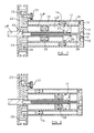
- the piston/cylinder unit shown in the drawings comprises a primary piston 11 operating in a primary cylinder zone, which it divides into chambers 12 and 13.
- the primary piston 11 is attached to a piston rod 11 a which is connected to the mechanism to be operated.
- a secondary piston operates in a secondary cylinder zone which it divides into chambers 15 and 16. It will be seen that the cylinder zones are co-axial, to reduce the overall length of the unit, but it is not essential that they be so.
- the chamber 12 is divided into two parts 12 a and 12 b by a tertiary piston 33, and the piston 33 is mounted on the piston rod 11 a so that the piston rod 11 a can move relative to the piston 33.
- One end cap 17 of the unit has apertures 18 and 19 for unions to provide pressure/exhaust connections for the chambers 13 and 16 respectively.
- the end cap 17 also has an aperture 34 for a union to provide a pressure/exhaust connection to the part 12 b of the chamber 12, the aperture 34 communicating with the part 12 b of the chamber 12 through a tube 38, a hollow interior 36 of the piston rod 11 a , and a drilling 37 in the piston 11.
- the tube 38 is secured to or is formed integrally with the end cap 17 and extends from the aperture 34 into the hollow interior 36 of the piston rod 11 a through a seal 39.
- the other end cap 21 includes a passageway 22 interconnecting the part 12 a of the chamber 12 and the chamber 15.
- the end cap 21 also includes a by-pass passageway 26 to by-pass the restriction provided by the valve 23.
- the by-pass passageway 26 is closable by a further shut off valve 28, which is also shown as a manually operated needle valve.
- valves 23, 25 and 28 need not be manually operated, but could be mechanically, pneumatically, hydraulically or electrically operated.
- the part 12 a of the chamber 12, the passageway 22, and the chamber 15 are filled with hydraulic fluid.
- variable restriction provided by the valve 23 controls the flow of hydraulic fluid, and hence the rate of displacement of the piston 11 and the piston rod 11 a after the piston 11 abuts the piston 33.
- the piston rod 11 a therefore advances rapidly at first and then at a controlled rate.
- the reverse operation is obtained by applying pneumatic pressure at aperture 19, while connecting apertures 18 and 34 to exhaust.
- Piston 14 is moved to the left towards a position shown in Figure 1, displacing hydraulic fluid through the passageway 22 past the valve 23.
- the hydraulic fluid in turn displaces the piston 33 which in turn displaces the piston 11 and the piston rod 11 a back towards the positions shown in Figure 1, at a rate controlled by the restriction provided by the valve 23.
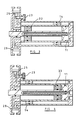
- Movement of the piston 33 may be arrested at, for example, the position shown in Figure 3, or at any other position, by closure of the valve 25.
- the primary piston 11 may then be returned to its starting position by applying pressure to the connection 34 and connecting aperture 18 to exhaust.
- the tertiary piston 33 is moved fully to the right (as shown in Figure 4) and the part 12 b of the chamber 12 is kept collapsed by connection to exhaust, so that the pistons 11 and 33 operate in unison.
- valve 28 is opened to open the by-pass passageway 26.
- valves 25 and 28 are both closed so that when the primary piston 11 abuts the tertiary piston 33, movement of the primary piston 11 will be arrested. If the piston/cylinder unit is used in this mode of operation, the position of the tertiary piston 33 can be varied with one or other of valves 25 and 28 open, by applying pneumatic pressure at aperture 34 with aperture 19 connected to exhaust, or by applying pneumatic pressure at aperture 19 with aperture 34 connected to exhaust.
- the piston/cylinder unit described above is extremely versatile and, as will be appreciated, can be operated in various different modes.
- the units may be single acting, with return springs incorporated, either in the unit itself, or in the mechanism to be operated.
Landscapes
- Engineering & Computer Science (AREA)
- Physics & Mathematics (AREA)
- Fluid Mechanics (AREA)
- Mechanical Engineering (AREA)
- General Engineering & Computer Science (AREA)
- Fluid-Pressure Circuits (AREA)
- Actuator (AREA)
- Supply Devices, Intensifiers, Converters, And Telemotors (AREA)
Applications Claiming Priority (2)
| Application Number | Priority Date | Filing Date | Title |
|---|---|---|---|
| GB888815449A GB8815449D0 (en) | 1988-06-29 | 1988-06-29 | Pneumatic cylinder |
| GB8815449 | 1988-06-29 |
Publications (2)
| Publication Number | Publication Date |
|---|---|
| EP0350190A2 true EP0350190A2 (fr) | 1990-01-10 |
| EP0350190A3 EP0350190A3 (fr) | 1990-11-14 |
Family
ID=10639564
Family Applications (1)
| Application Number | Title | Priority Date | Filing Date |
|---|---|---|---|
| EP19890306464 Withdrawn EP0350190A3 (fr) | 1988-06-29 | 1989-06-26 | Cylindre pneumatique |
Country Status (4)
| Country | Link |
|---|---|
| US (1) | US5009068A (fr) |
| EP (1) | EP0350190A3 (fr) |
| JP (1) | JPH0285506A (fr) |
| GB (2) | GB8815449D0 (fr) |
Cited By (3)
| Publication number | Priority date | Publication date | Assignee | Title |
|---|---|---|---|---|
| DE4414907A1 (de) * | 1994-04-28 | 1995-11-02 | Rexroth Mannesmann Gmbh | Mehrfachzylinder, insbesondere für Pressen |
| DE102004044962A1 (de) * | 2004-09-16 | 2006-04-06 | Liebherr-Aerospace Lindenberg Gmbh | Druckmittelbetätigte Stellvorrichtung |
| DE102006028878A1 (de) * | 2006-06-21 | 2007-12-27 | Zf Friedrichshafen Ag | Hydraulische Stelleinheit für ein Kraftfahrzeug |
Families Citing this family (13)
| Publication number | Priority date | Publication date | Assignee | Title |
|---|---|---|---|---|
| US5203250A (en) * | 1990-12-21 | 1993-04-20 | Deere & Company | Fluid cylinder mechanism |
| US5634764A (en) * | 1994-08-12 | 1997-06-03 | Replogle; Charles R. | Workpiece placement system and method having a vacuum holding the workpiece |
| US5819635A (en) * | 1996-12-19 | 1998-10-13 | Moonen; Raymond J. | Hydraulic-pneumatic motor |
| US6575019B1 (en) | 2000-01-14 | 2003-06-10 | Chandler Engineering Company Llc | Reciprocating drive/pump system and reciprocating capillary viscometer utilizing same |
| FI115925B (fi) * | 2000-03-21 | 2005-08-15 | Hydroll Oy | Hydraulijärjestelmä ja siihen sovitettava vaimennin |
| US6862972B2 (en) * | 2002-12-23 | 2005-03-08 | James Morrison | Additive injection device |
| US20040121747A1 (en) * | 2002-12-24 | 2004-06-24 | Sy-Kang Shen | Kit of a local oscillator of an airborne VHF multimode communication transceiver |
| US6895854B1 (en) | 2003-05-05 | 2005-05-24 | Wesley M. Plattner | Power cylinder apparatus for supplying varying actuation forces |
| US8746128B2 (en) * | 2011-03-01 | 2014-06-10 | Tonand Brakes Inc. | Variable displacement piston-in-piston hydraulic unit |
| US9784253B2 (en) * | 2014-07-31 | 2017-10-10 | Tonand Brakes Inc. | Variable displacement piston-in-piston hydraulic unit |
| GB2533320A (en) | 2014-12-16 | 2016-06-22 | Airbus Operations Ltd | Actuator |
| WO2020233744A1 (fr) * | 2019-05-17 | 2020-11-26 | Alfred Jäger GmbH | Cylindre pneumatique modulaire et utilisation de celui-ci dans une broche de moteur |
| RS20210872A1 (sr) * | 2021-07-09 | 2023-01-31 | Igor Karafilovski | Prečistač vazduha |
Family Cites Families (19)
| Publication number | Priority date | Publication date | Assignee | Title |
|---|---|---|---|---|
| US2605751A (en) * | 1949-08-10 | 1952-08-05 | Perry Fay Company | Fluid pressure tool slide control assembly |
| US2596471A (en) * | 1950-01-21 | 1952-05-13 | Richard M Densmore | Variable-stop hydraulic system |
| US2918902A (en) * | 1954-12-06 | 1959-12-29 | Vickers Inc | Single station variable length stroke motor control system |
| US2860604A (en) * | 1956-10-08 | 1958-11-18 | Samuel Krivit | Air and liquid operated apparatus for intermittently feeding a buffing bar to a buffing wheel |
| US3005444A (en) * | 1959-07-27 | 1961-10-24 | Dumore Company | Control means for fluid actuated work cylinders |
| US2976845A (en) * | 1959-12-18 | 1961-03-28 | Modernair Corp | Pneumatic-hydraulic drive cylinder |
| US3190077A (en) * | 1963-01-04 | 1965-06-22 | Harold W Scholin | Fluid motor |
| DE1502839C3 (de) * | 1963-05-29 | 1974-02-28 | Erhard 6800 Mannheimkaefertal Lehle | Lufthydraulischer Schubkolbentrieb |
| GB1183521A (en) * | 1966-05-16 | 1970-03-11 | P C Payne & Company Keynsham L | Improvements relating to pneumatic Actuators |
| FR1504765A (fr) * | 1966-10-26 | 1967-12-08 | Faiveley Sa | Vérin oléopneumatique à structure étagée |
| GB1242128A (en) * | 1968-11-26 | 1971-08-11 | George Engineering Company Ltd | Pressure-operated piston device |
| FR2080242A5 (fr) * | 1970-02-27 | 1971-11-12 | Int Harvester Co | |
| US3866727A (en) * | 1974-01-18 | 1975-02-18 | Dana Corp | Fluid operated clutch and brake with dashpot |
| DE2608904A1 (de) * | 1976-03-04 | 1977-09-08 | Willy Ehrhardt | Hydro-pneumatische vorschub-zylindereinheit |
| SU840511A1 (ru) * | 1979-05-07 | 1981-06-23 | Предприятие П/Я Г-4725 | Пневмогидравлический аккумул -TOP |
| GB2080419B (en) * | 1980-07-24 | 1983-12-14 | Ato Inc | An adjustable stroke cylinder |
| DE3030599A1 (de) * | 1980-08-11 | 1982-03-18 | A-T-O Inc., Willoughby, Ohio | Zylinder und mit kolben/zylinder-baugruppen mit regelbarem hub |
| DE8328461U1 (de) * | 1983-10-04 | 1986-01-16 | Gebr. Gierlich KG, 5300 Bonn | Hydropneumatische Vorschubvorrichtung |
| GB2178109A (en) * | 1985-07-25 | 1987-02-04 | David William Arnold | Actuator |
-
1988
- 1988-06-29 GB GB888815449A patent/GB8815449D0/en active Pending
-
1989
- 1989-06-22 GB GB8914339A patent/GB2221956B/en not_active Expired - Lifetime
- 1989-06-26 EP EP19890306464 patent/EP0350190A3/fr not_active Withdrawn
- 1989-06-27 US US07/372,054 patent/US5009068A/en not_active Expired - Fee Related
- 1989-06-29 JP JP1168234A patent/JPH0285506A/ja active Pending
Cited By (4)
| Publication number | Priority date | Publication date | Assignee | Title |
|---|---|---|---|---|
| DE4414907A1 (de) * | 1994-04-28 | 1995-11-02 | Rexroth Mannesmann Gmbh | Mehrfachzylinder, insbesondere für Pressen |
| DE102004044962A1 (de) * | 2004-09-16 | 2006-04-06 | Liebherr-Aerospace Lindenberg Gmbh | Druckmittelbetätigte Stellvorrichtung |
| DE102004044962B4 (de) * | 2004-09-16 | 2008-04-10 | Liebherr-Aerospace Lindenberg Gmbh | Druckmittelbetätigte Stellvorrichtung |
| DE102006028878A1 (de) * | 2006-06-21 | 2007-12-27 | Zf Friedrichshafen Ag | Hydraulische Stelleinheit für ein Kraftfahrzeug |
Also Published As
| Publication number | Publication date |
|---|---|
| GB2221956A (en) | 1990-02-21 |
| GB8914339D0 (en) | 1989-08-09 |
| EP0350190A3 (fr) | 1990-11-14 |
| JPH0285506A (ja) | 1990-03-27 |
| US5009068A (en) | 1991-04-23 |
| GB8815449D0 (en) | 1988-08-03 |
| GB2221956B (en) | 1992-06-17 |
Similar Documents
| Publication | Publication Date | Title |
|---|---|---|
| US5009068A (en) | Pneumatic cylinder with positioning, braking, and feed rate control | |
| US5385218A (en) | Rack and pinion pneumatic actuator with counter-pressure control and damping device | |
| US4907495A (en) | Pneumatic cylinder with integral concentric hydraulic cylinder-type axially compact brake | |
| US5161449A (en) | Pneumatic actuator with hydraulic control | |
| CA2211474C (fr) | Multiplicateur de pression pour fluides, notamment pour liquides hydrauliques | |
| US4172698A (en) | Pressure gas operated pump | |
| EP0304210B1 (fr) | Pompe à double membrane | |
| US5058385A (en) | Pneumatic actuator with hydraulic control | |
| US2478790A (en) | Controlled stroke cylinder | |
| US4241581A (en) | Synchronizer for hydraulic actuators | |
| US4790728A (en) | Dual-rigid-hollow-stem actuators in opposite-phase slurry pump drive having variable pumping speed and force | |
| US3796050A (en) | High energy rate actuator | |
| US5226346A (en) | Axial piston type pressure medium servomotor control device | |
| US5097747A (en) | Pilot adjuster-connector for adjusting the speed of pneumatic pressure cylinders | |
| US4240329A (en) | Fluid pressure servo detent mechanism | |
| US3315768A (en) | Hydraulic shaft positioning mechanism | |
| US4197785A (en) | Hydraulic actuator cushioning device | |
| US3733965A (en) | Control system for fluid cylinder | |
| EP0428406A1 (fr) | Moteur alternatif | |
| US4491055A (en) | Control of continuous reciprocation of a fluid power cylinder | |
| US6408739B1 (en) | Pneumatic cylinder with internal liquid dampening means | |
| US3610107A (en) | Torque cylinder | |
| US4463656A (en) | Pneumatic motor drive | |
| US4089172A (en) | Position controller | |
| US4627328A (en) | Hydraulic actuator-control arrangement for concrete pump |
Legal Events
| Date | Code | Title | Description |
|---|---|---|---|
| PUAI | Public reference made under article 153(3) epc to a published international application that has entered the european phase |
Free format text: ORIGINAL CODE: 0009012 |
|
| AK | Designated contracting states |
Kind code of ref document: A2 Designated state(s): AT DE FR GB IT SE |
|
| PUAL | Search report despatched |
Free format text: ORIGINAL CODE: 0009013 |
|
| RHK1 | Main classification (correction) |
Ipc: F15B 11/06 |
|
| AK | Designated contracting states |
Kind code of ref document: A3 Designated state(s): AT DE FR GB IT SE |
|
| 17P | Request for examination filed |
Effective date: 19910508 |
|
| STAA | Information on the status of an ep patent application or granted ep patent |
Free format text: STATUS: THE APPLICATION IS DEEMED TO BE WITHDRAWN |
|
| 18D | Application deemed to be withdrawn |
Effective date: 19921231 |