EP0350197B1 - Automatische Vorrichtung zum Brühen von Kaffee - Google Patents
Automatische Vorrichtung zum Brühen von Kaffee Download PDFInfo
- Publication number
- EP0350197B1 EP0350197B1 EP89306564A EP89306564A EP0350197B1 EP 0350197 B1 EP0350197 B1 EP 0350197B1 EP 89306564 A EP89306564 A EP 89306564A EP 89306564 A EP89306564 A EP 89306564A EP 0350197 B1 EP0350197 B1 EP 0350197B1
- Authority
- EP
- European Patent Office
- Prior art keywords
- reservoir
- coffee
- brewing
- cam
- bottom wall
- Prior art date
- Legal status (The legal status is an assumption and is not a legal conclusion. Google has not performed a legal analysis and makes no representation as to the accuracy of the status listed.)
- Expired - Lifetime
Links
Images




Classifications
-
- A—HUMAN NECESSITIES
- A47—FURNITURE; DOMESTIC ARTICLES OR APPLIANCES; COFFEE MILLS; SPICE MILLS; SUCTION CLEANERS IN GENERAL
- A47J—KITCHEN EQUIPMENT; COFFEE MILLS; SPICE MILLS; APPARATUS FOR MAKING BEVERAGES
- A47J31/00—Apparatus for making beverages
- A47J31/04—Coffee-making apparatus with rising pipes
- A47J31/057—Coffee-making apparatus with rising pipes with water container separated from beverage container, the hot water passing the filter only once i.e. classical type of drip coffee makers
- A47J31/0573—Coffee-making apparatus with rising pipes with water container separated from beverage container, the hot water passing the filter only once i.e. classical type of drip coffee makers with flow through heaters
-
- A—HUMAN NECESSITIES
- A47—FURNITURE; DOMESTIC ARTICLES OR APPLIANCES; COFFEE MILLS; SPICE MILLS; SUCTION CLEANERS IN GENERAL
- A47J—KITCHEN EQUIPMENT; COFFEE MILLS; SPICE MILLS; APPARATUS FOR MAKING BEVERAGES
- A47J31/00—Apparatus for making beverages
- A47J31/06—Filters or strainers for coffee or tea makers ; Holders therefor
- A47J31/0605—Filters or strainers for coffee or tea makers ; Holders therefor with a valve at the filter-outlet; Anti-drip devices
- A47J31/061—Filters or strainers for coffee or tea makers ; Holders therefor with a valve at the filter-outlet; Anti-drip devices activated by the beverage container
-
- A—HUMAN NECESSITIES
- A47—FURNITURE; DOMESTIC ARTICLES OR APPLIANCES; COFFEE MILLS; SPICE MILLS; SUCTION CLEANERS IN GENERAL
- A47J—KITCHEN EQUIPMENT; COFFEE MILLS; SPICE MILLS; APPARATUS FOR MAKING BEVERAGES
- A47J31/00—Apparatus for making beverages
- A47J31/44—Parts or details or accessories of beverage-making apparatus
- A47J31/50—Urns with devices for keeping beverages hot or cool
-
- A—HUMAN NECESSITIES
- A47—FURNITURE; DOMESTIC ARTICLES OR APPLIANCES; COFFEE MILLS; SPICE MILLS; SUCTION CLEANERS IN GENERAL
- A47J—KITCHEN EQUIPMENT; COFFEE MILLS; SPICE MILLS; APPARATUS FOR MAKING BEVERAGES
- A47J31/00—Apparatus for making beverages
- A47J31/44—Parts or details or accessories of beverage-making apparatus
- A47J31/52—Alarm-clock-controlled mechanisms for coffee- or tea-making apparatus ; Timers for coffee- or tea-making apparatus; Electronic control devices for coffee- or tea-making apparatus
-
- A—HUMAN NECESSITIES
- A47—FURNITURE; DOMESTIC ARTICLES OR APPLIANCES; COFFEE MILLS; SPICE MILLS; SUCTION CLEANERS IN GENERAL
- A47J—KITCHEN EQUIPMENT; COFFEE MILLS; SPICE MILLS; APPARATUS FOR MAKING BEVERAGES
- A47J31/00—Apparatus for making beverages
- A47J31/44—Parts or details or accessories of beverage-making apparatus
- A47J31/52—Alarm-clock-controlled mechanisms for coffee- or tea-making apparatus ; Timers for coffee- or tea-making apparatus; Electronic control devices for coffee- or tea-making apparatus
- A47J31/525—Alarm-clock-controlled mechanisms for coffee- or tea-making apparatus ; Timers for coffee- or tea-making apparatus; Electronic control devices for coffee- or tea-making apparatus the electronic control being based on monitoring of specific process parameters
- A47J31/5253—Alarm-clock-controlled mechanisms for coffee- or tea-making apparatus ; Timers for coffee- or tea-making apparatus; Electronic control devices for coffee- or tea-making apparatus the electronic control being based on monitoring of specific process parameters of temperature
Definitions
- This invention relates to automatic coffee brewing apparatus.
- US A-4,682,537 discloses a commercial vending machine which provides probes arranged at different levels for sensing the amount of brewed coffee remaining. When a tank containing the brewed coffee is approximately one-third full, a "coffee low" light is displayed and a new coffee making cycle may be initiated either automatically or manually.
- USA-4,621,571 provides a plurality of satellite receptacle units for the storage and dispensing of hot coffee which can be filled from a central brewing unit.
- a safety switch assembly assures that a brewing cycle cannot be initiated unless the brew chamber is properly aligned to discharge into a correspondingly aligned empty satellite unit.
- a sophisticated commercial expresso coffee machine which brews coffee pods placed in one or more extraction heads. It includes an electronic control system which operates all functions of the machine including maintaining careful monitoring and control of the water temperature and the volume of hot water delivered to each extraction head.
- the machine diagnoses itself for possible failures and depleted supplies by showing on a display in code the kind of failure or of needed supply, for example, coffee, water.
- Each step of an operation is controlled until completion and the machine proceeds to the next only upon confirmation of proper execution of the earlier step. In the absence of confirmation, subsequent operations are not performed. Instead, a digital code signal is displayed in the machine panel corresponding to the failure or depletion in the machine.
- Manually initiated coffee brewing apparatus including a mill mechanism and utilizes a heater circuit containing a cover switch and a pair of other switches which control the heater mechanism. If all switches are closed, once initiated, a brew cycle proceeds to conclusion. Otherwise the apparatus remains inoperative except to digitally display a difficulty, such as "LID", to indicate that the cover is open.
- a difficulty such as "LID”
- GB 1597834 discloses an apparatus, intended for making tea, which comprises a reservoir in which an electrical heating element is positioned, which reservoir can be removed from the apparatus, thus to disconnect the heating element.
- a reservoir in which an electrical heating element is positioned, which reservoir can be removed from the apparatus, thus to disconnect the heating element.
- water is heated in the reservoir it is supplied from the reservoir through a conduit directly into a vessel or tea pot in which the tea is brewed.
- Such an apparatus would need substantial modification to allow it to be used for brewing coffee in a conventional way, i.e. by passing hot water through ground coffee.
- the apparatus does comprise a tiltable platform, which is tilted when a full reservoir is pushed into its correct position, thus allowing the apparatus to operate only when a reservoir containing a required amount of water is in its correct position.
- the tiltable platform may become wedged, which may either prevent the apparatus from working or enable the heater to be actuated when the various components are not properly positioned.
- the apparatus relies on the temperature of the heating element to actuate the thermostatic control, so that should the conduit from the reservoir to the container be blocked, the apparatus will continue to heat the water until the reservoir has boiled dry and the temperature of the heater rises to an appropriate level.
- a coffee making apparatus which comprises a housing, a self contained water reservoir movable between a withdrawn position and an operative position in the housing, a brewing station, a supply conduit in communication with and extending between the brewing station and the reservoir when the reservoir is in its operative position to enable water to flow from the reservoir to the brewing station and an electrical hot water generator for heating water in the conduit between the reservoir and the brewing station as the water flows from the reservoir to the brewing station and a removable vessel for receiving brewed coffee from the brewing station and movable between a withdrawn position and a coffee receiving position.
- this apparatus does comprise a reservoir comprising an outlet section with an automatically closing valve, which closes on the reservoir being removed from its operative position, it does not comprise any means for preventing the apparatus operating if, for example, there is no vessel in position to receive the coffee or no water in the reservoir.
- the present invention provides automatic coffee brewing apparatus comprising: a housing a self-contained water reservoir movable between a withdrawn position and an operative position in the housing; a brewing station; a water supply conduit in communication with and extending between said brewing station and said reservoir when said reservoir is in said operative position to enable the flow of water from said reservoir to said brewing station; and an electrically energizable hot water generator intermediate the brewing station and the reservoir for heating water in said supply conduit to a sufficient extent as it flows from said reservoir to said brewing station to enable coffee to be brewed at said brewing station; a vessel for receiving brewed coffee from the brewing station and movable between a withdrawn position and a coffee receiving position characterized in that the apparatus comprises control means for initiating a brewing cycle and thereafter enabling the brewing cycle to proceed to its conclusion and including interrupt means for preventing the brewing cycle from proceeding in the event any one of the following operating conditions is not satisfied
- a coffee brewing system which enables a brew cycle to be initiated manually or automatically at a preset time, but which prevents a brew cycle from proceeding if the aforementioned required operating conditions are not satisfied. If, all operating conditions become satisfied again after a brew cycle, one underway, is interrupted, the brew cycle continues on to completion.
- Visual and audible signals indicate the current status of the brew cycle and/or of the brewing unit.
- An insulated carafe is used as the vessel to receive brewed coffee thereby eliminating the need for a keep warm plate.
- the unit may be mounted under a cabinet to thereby maximize usable counter top space and the coffee basket utilizes a dispensing valve which is opened by the carafe when inserted into position but which closes when the carafe is withdrawn.
- an electronic control system is used for initiating a brewing cycle and, thereafter, for enabling the brewing cycle to proceed to its conclusion. It allows for a brewing cycle to be initiated either manually or automatically at a preset time.
- the electronic control system also provides for interrupting a brewing cycle in the event any of the aforesaid operating conditions is not satisfied. Specifically, the brew cycle will not commence, or continue, in the event the water reservoir is not in its operating position, or if there is no water in the water reservoir, or if the carafe is not in its operating position. Also, the apparatus will not operate in the event of severe calcification of the system requiring cleaning in a known manner.
- This ability of the apparatus to interrupt a brew cycle unless all conditions are fulfilled eliminates possible damage to the apparatus, excessive waste of materials and energy, and avoids a soiled work area of the type which can occur in the event a carafe or other vessel for receiving the brewed coffee is not positioned to receive the coffee during the brew cycle.
- Another benefit of preferred embodiments is a significant increase achieved of usable counter space.
- an insulated carafe is used which obviates the necessity for a warmer plate beneath the coffee receiving vessel. Accordingly, the counter top itself is completely free for use.
- the carafe in its operative brewed coffee receiving position, is suspended from an upper rim. When not in use, the carafe can be removed, thereby further increasing the space between the countertop and the underside of the coffee brewing available for use for other purposes.
- Still another benefit of the preferred embodiment resides in its construction according to which insertion of the self-contained water reservoir to its operating position serves to manually reset the thermostat associated with the hot water generator and positioned at the rear of the apparatus.
- the resetting operation is achieved without the use of complex linkages or with the requirement of a manually operated mechanism representing still an additional operation to be performed by the user.
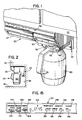
- the system 20 includes a main housing unit 22 which contains all of the necessary elements for brewing coffee, specifically, a self contained water reservoir 24, a water heating and pumping system 26, and a brewing station 28 including a coffee basket 30.
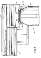
- the main housing unit (22) may be attached to the underside of a cabinet 32 or of any horizontal surface by means of an intermediate bracket 34 (Fig. 4) and secured with screws or other suitable mounting devices.
- the housing unit 22 In its mounted condition, especially as seen in Fig. 2, the housing unit 22 is of minimal height and provides a maximum of room above a countertop 36 and, especially, between the countertop and the cabinet 32.
- the lowest part of the housing unit 22 is located at its rearmost side adjacent a wall 38 and, therefore, substantially out of the way.
- a vessel for receiving brewed coffee is preferably in the form of an insulated carafe 40 which is an independent part of the coffee brewing system 20.
- the carafe is provided with a rim 42 at its upper regions which is supportively and slidably received by a pair of opposed support tracks 44.
- the carafe does not require bottom support while in its operative position. It can, therefore, be much taller than traditional coffee receiving vessels intended to be positioned under a cabinet thereby improving the ease with which coffee can be poured from it.
- the relationship between the rim 42 and the support 44 also enables the carafe to be readily moved from a withdrawn position to an operative position as illustrated in Figs. 1-4.
- the water reservoir 24 is self contained and is generally in the form of an enclosed drawer which is slidably received on a shelf 46 of the housing unit 22.
- a plurality of spaced parallel runners 48 integral with the reservoir 24 and extending downwardly therefrom serve to improve the slidability of the reservoir on the shelf 46.
- the reservoir 24 can be withdrawn from the housing unit 22, filled from a faucet with an amount of water equivalent to the number of cups of coffee desired, then reinserted into the unit.
- an outlet valve 50 which is normally biased closed is engaged by a needle 52 mounted within a fitting 54 located at an extreme end of the water heating and pumping system 26.
- the water heating and pumping system 26 includes a water supply conduit 56 which is in communication with and extends between the fitting 54 and the brewing station 28. It includes a descending leg 58, a transverse leg 60, and an ascending leg 64.
- the system 26 also includes an electrically energizable hot water generator 62 immediately adjacent the transverse leg 60 which operates in a known manner for heating of water in the supply conduit to a sufficient extent as it flows from the reservoir 24 to the brewing station 28 to enable coffee to be brewed at the brewing station.
- an electrically energizable hot water generator 62 immediately adjacent the transverse leg 60 which operates in a known manner for heating of water in the supply conduit to a sufficient extent as it flows from the reservoir 24 to the brewing station 28 to enable coffee to be brewed at the brewing station.
- water flows from the reservoir 24 through the descending leg 58, then across the transverse leg 60 where it is heated by the hot water generator 62. Thereafter, the resulting water and steam mixture rises through the ascending leg 64 to a shower plate 66 which overlies the coffee basket 30.
- a filter 68 of paper or other suitable material is positioned in the coffee basket 30 to receive fresh ground coffee 70.
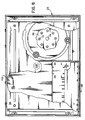
- Hot water pumped by the generator 62 through the ascending leg 64 passes through a plurality of suitably positioned openings 72, 74 (see Fig. 8) in the shower plate 66 onto and through the ground coffee 70 and filter 68 for eventual reception by the carafe 40 when in its operating position.
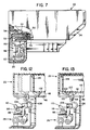
- the coffee basket 30 is seen to include a side wall 76 and a bottom wall 78 for supporting the filter 68 and ground coffee 70 therein.
- the bottom wall 78 is provided with at least one centrally disposed discharge opening 80 and generally slopes downwardly from the sidewall to the discharge opening.
- a generally disc shaped, contoured, cam plate 82 underlies the bottom wall 78 and is substantially coextensive therewith.
- the cam plate 82 has a concave surface which faces the bottom wall and a convex surface which faces away from the bottom wall.
- a pin member 84 is fixed to the cam plate 82 and extends in a transverse direction away from a central region of the concave surface of the cam plate, then freely through the discharge opening 80 in the bottom wall 78.
- a deformable valve member 86 composed of rubber or other suitable material is fixed to the pin member distant from the cam plate 82.
- a spider spring member 88 is interposed between the bottom wall 78 and the cam plate 82 and serves to bias the cam plate 82 away from the bottom wall 78.
- the spider spring member 88 includes a central ring 90 which is coaxially received over a circular rib 92 which protrudes outwardly from the bottom wall 78.
- a plurality of resilient legs 94 extend radially outwardly from the central ring 90 and also extend away from the bottom wall 78 when it assumes the relationship illustrated in Figs. 9 and 10. The central ring 90 bears against the bottom wall 78 while the extremities of the legs 94 bear against the concave surface of the cam plate 82.
- valve member 86 engages a valve seat defined as the intersection within the coffee basket of the bottom wall 78 and the discharge opening 80.
- coffee is normally prevented from issuing from the coffee basket.
- an upper lid 96 of the carafe engages the cam plate 82, unseating the valve member 86 and allowing coffee to flow, by gravity, into the carafe.
- the cam plate 82 returns to its relaxed position, the valve member again seals the discharge opening 80 and any liquid coffee remaining in the coffee basket 30 is prevented from dripping, undesirably, upon the countertop 36 or whatever else is located beneath the housing unit 22.
- a second circular rib 97 concentric with the first rib 92, similarly extends away from the bottom wall 78.
- the cam plate 82 terminates at an upturned circular rim 82A which is concentric with and proximate to the second rib 97.
- the circular rim and the second rib are mutually cooperable to guide the cam plate 82 between the first and second positions, the second rib being engageable with the cam plate and the circular rim being engageable with the extended surface of the bottom wall when the cam plate is in the valve unseating position.
- thermostat, or temperature sensitive switch, 98 is commonly available from numerous sources, but one example of a switch suitable for purposes is Model No. 1NT03 manufactured by Texas Instruments, Inc. of Austin, Texas being of a manual reset type, the switch 98 need only be pressed once, without the need of continuing to press the switch to maintain its actuation.
- An actuating mechanism 100 has been devised to accomplish this end result in combination with another operation which must also be performed.
- a pair of parallel, spaced, support ears 104 are suitably mounted on a housing encompassing the transverse leg 60 and the hot water generator 62.
- a stub shaft 106 extends between and is supported by the ears 104, and, in turn, supports an arcuate shaped, resilient, rocker cam 108 which extends between an actuator member 110 at one end and a cam member 112 fixed to its opposite end.
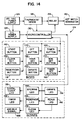
- the control system 124 operates to initiate a brewing cycle and, once the brewing cycle has been initiated, enabling it to proceed to its conclusion. However, the control system also operates to prevent the brewing cycle from proceeding in the event any one of a plurality of operating conditions are not implemented.
- the brewing system 20 is AC powered as represented by a customary 120 VAC power supply 126.
- the power supply 126 energizes a DC power supply 128 which in turn powers the electronic portion of the control system.
- a central component of the control system is a microcontroller 130 of known design, one example suitable for purposes of the invention being Model No. TMS 1000 manufactured by Texas Instruments, Inc. of Austin, Texas.
- the microcontroller serves to assure that a proper sequence of steps in the brew cycle is performed and if interrupted for failure of an operating condition to be implemented, will continue with the normal sequence of the brew cycle from the point left off when such an operating condition or conditions are once again implemented.
- a face plate or escutcheon 132 is provided on the housing unit 22 and indicates a number of inputs to the brewing system which can be performed by the user as well as a number of outputs for indicating the operating condition of the system.
- Table 1 which follows, provides a functional description of the operative, or input, components of the brewing system 20 and Table 2, which also follows, similarly provides a description of the informational, or output, components of the system.
- a digital clock 134 which, preferably, utilizes seven segment LED characters 135 (Fig. 14), flashes "12:00 AM".
- TOD time of day
- the clock 134 will display the correct time but all other functions of the brewing system remain in the dormant state until a start button 142 or a timer button 164 (to be described) has been pressed.
- a brew cycle may be initiated by the brewing system 20 either manually or automatically.
- the user actuates the start button 142 and if all operating conditions have been implemented, the microcontroller 130 will see to it that the brew cycle is performed to its conclusion resulting in an amount of brewed coffee within the carafe 40 consistent with the amount of fresh ground coffee 70 placed by the user in the coffee basket 30 and a corresponding amount of water introduced to the water reservoir 24.
- a brewing lamp 144 (Figs. 14 & 15) is lighted to indicate this fact.
- a ready lamp 146 becomes lighted and the brewing lamp 144 turns off.
- the operation of the ready lamp 146 and deactivation of the brewing lamp 144 to be delayed by a short period of time, for example, 40 seconds or in any event less than one minute in order to accommodate any remaining drippage of coffee from the coffee basket 30 into the carafe 40.
- the water reservoir 24 must be in its operative position with the valve 50 matingly engaged with the fitting 54 to assure its connection to the water supply conduit 56. In this operative position, the tab 102 will already have actuated the reset button 118 of the thermostat switch 98 to thereby move the thermostat switch to its closed position. However, not only must the reservoir 24 be in its operative position, but it must also contain a sufficient amount of water for a meaningful brew cycle to commence.
- a reservoir display means in the form of a lamp 148 (Fig. 14 and 15) is caused to be lighted to indicate this failed condition.
- the carafe 40 must be in the operative position (Figs. 1-3) engaged with a button 150 (see especially Figs. 5 and 10) slidably received on the housing unit 22 for selective engagement with an arm 152 of a microswitch 154. So long as the carafe is in its operative position, a carafe lamp 156 (Figs. 14 and 15) remains unlighted, but when the carafe is withdrawn from its operative position, the lamp is lighted to indicate that the condition is no longer implemented and the brew cycle is interrupted.
- a "clean" display means in the form of a lamp 158 which is lighted in response to operation of a sensing mechanism 160.
- the clean lamp 158 becomes lighted only after the ready lamp 146 becomes lighted at the end of the brew, that is, after the thermostat switch 98 opens.
- the clean lamp 158 serves to notify the user that the water supply conduit 56 needs cleaning in the known manner, but still permits a brew cycle to continue to its conclusion.
- the ready lamp 146 would not be activated, nor would the clean lamp 158 be activated, since the former drives the latter.
- the microcontroller 130 would be informed by the thermostat switch 98 (Fig. 14) that it is in the open position and would operate a relay 159 to open and thereby deenergize the hot water generator 62.
- the thermostat switch 98 would be caused to open because of the excessive heat generated in the absence of the cooling effect of water flowing through the supply conduit 56.
- the sensing mechanism 160 may be of the novel construction disclosed in our European Patent Application file herewith , , and entitled "Calcification Indicator".
- the sensing mechanism 160 operates on the principal that the presence of water in the supply conduit 56 upstream of the hot water generator 62 after the thermostat switch 98 opens is indicative of the presence of substantial mineral deposits located primarily in the transverse leg 60 which thereby prevents all the water initially in the reservoir 24 from being received at the brewing station 28 prior to completion of the brew cycle.
- the user For operating the brewing system 20 in the automatic mode, the user must set the timer for the clock 134 to the desired time for initiating a brew cycle.
- the time of brew may be set by pressing a timer set button 162 and, while holding it pressed, pressing in sequence the hour set button 138 and the minute set button 140. Time so chosen is displayed by the clock 134 so long as the timer set button 162 is held depressed.
- the timer button 164 in order to activate the automatic mode, the timer button 164 must be depressed which causes a timer lamp 166 to be lighted to indicate that the brewing system 20 has now been set for automatic operation. Depressing the timer button 164 also causes the clock 134 to display the preset time for the brew cycle to commence as previously set. Upon releasing the timer button 164, the clock 134 returns to its display of the time of day.
- the brew cycle will indeed commence and continue to its conclusion so long as all of the conditions continue to be so implemented. However, in the event a condition is not implemented at the preset time, a brewing cycle will not commence even if all conditions are implemented at some later time.
- an audible signal as, for example, a piezoelectric beeper is operated to cause a double beep at a one Hz rate to so inform the user.
- This audible signal is indicated in Fig. 14 by a reference numeral 168.
- an off button 170 may be momentarily depressed. This serves to return the brewing system 20 to a standby or waiting mode in which only the clock 134 continues to display the time of day.
- a microswitch 222 (Fig. 8) is arranged at the top of housing 22 and is closed when the water reservoir 24 is in its operative position.
- the microswitch 222 is connected to the microcontroller 130.
- a brewing cycle can only proceed when the microswitch 222 is closed.
Landscapes
- Engineering & Computer Science (AREA)
- Food Science & Technology (AREA)
- Apparatus For Making Beverages (AREA)
Claims (20)
- Automatische Vorrichtung zum Brühen von Kaffee mit:
einem Gehäuse (22);
einem zwischen einer zurückgezogenen Position und einer Betriebsposition in dem Gehäuse bewegbaren unabhängigen Wasserbehälter (24);
einer Brühstation (28);
einer Wasserzufuhr-Rohrleitung (56), die mit der Brühstation (28) und dem Behälter (24) in Verbindung steht und sich dazwischen erstreckt, wenn der Behälter (24) in der Betriebsposition ist, um den Wasserfluß von dem Behälter (24) zu der Brühstation (28) zu ermöglichen; und
einem elektrisch erregbaren Warmwassererzeuger (62) zwischen der Brühstation (28) und dem Behälter (24) zum Erwärmen von Wasser in der Zufuhrrohrleitung (56) in ausreichendem Maße, wenn es von dem Behälter (24) zu der Brühstation (28) fließt, um ein Brühen von Kaffee an der Brühstation (28) zu ermöglichen;
einem Gefäß (40) zum Aufnehmen von gebrühtem Kaffee von der Brühstation, das zwischen einer zurückgezogenen Position und einer Position zum Aufnehmen von Kaffee bewegbar ist;
dadurch gekennzeichnet, daß
die Vorrichtung eine Steuereinrichtung zum Starten eines Brühzyklus und um danach zu ermöglichen, daß der Brühzyklus bis zu seiner Beendigung fortschreitet, aufweist, wobei Unterbrechungseinrichtungen eingeschlossen sind, um den Brühzyklus in dem Fall, daß eine der folgenden Betriebsbedingungen nicht erfüllt ist, am Fortschreiten zu hindern(a) das Gefäß (40) ist in seiner Position zum Aufnehmen von Kaffee(b) der Behälter (24) ist in seiner Betriebsposition oder(c) in dem Behälter (24) befindet sich Wasser,
wobei die Unterbrechungseinrichtungen aufweisen(i) einen Karaffen-Schalter (154), der in einer offenen, abschaltenden Position ist, wenn das Gefäß (40) nicht in seiner Position zum Aufnehmen von Kaffee ist(ii) eine Behälter-Schaltereinrichtung, die in einer offenen, abschaltenden Position ist, wenn der Behälter (24) nicht in seiner Betriebsposition ist(iii) eine temperaturempfindliche Schaltereinrichtung (98), die in eine offene, abschaltende Position bewegt wird, wenn die Temperatur in der Zufuhrrohrleitung (56) wegen der Abwesenheit von Wasserfluß dort hindurch eine gewünschte Temperatur überschreitet. - Automatische Vorrichtung zum Brühen von Kaffee nach Anspruch 1, dadurch gekennzeichnet, daß die Steuereinrichtung einen Mikrokontroller (130) einschließt, der so wirkt, daß er in dem Fall, daß irgendeine der zuvor erwähnten Betriebsbedingungen nicht erfüllt ist, die Fortsetzung eines bereits im Fortschreiten befindlichen Brühzyklus verhindert, und daß er den Brühzyklus wieder aufnimmt und ermöglicht, daß der Brühzyklus bis zu seiner Beendigung fortschreitet, wenn alle der zuvor erwähnten Betriebsbedingungen wiederum erfüllt sind.
- Automatische Vorrichtung zum Brühen von Kaffee nach Anspruch 1 oder 2, dadurch gekennzeichnet, daß die Steuereinrichtung eine Zeitgeber (Timer)-Einrichtung (134, 162, 164) zum Starten eines Brühzyklus zu einer voreingestellten Aktivierungszeit einschließt, wobei die Unterbrechungseinrichtungen betriebsfähig sind, um den Start des Brühzyklus zu der voreingestellten Aktivierungszeit zu verhindern, wenn die zuvor erwähnten Betriebsbedingungen nicht erfüllt sind.
- Automatische Vorrichtung zum Brühen von Kaffee nach Anspruch 3, dadurch gekennzeichnet, daß die Zeitgebereinrichtung einschließt:
eine Uhr (134) zum Anzeigen der Tageszeit und Einrichtungen (136, 138, 140) zum Einstellen der angezeigten Zeit auf die korrekte lokale Zeit;
Speichereinrichtungen zum Speichern der voreingestellten Aktivierungszeit und Einrichtungen (162, 138, 140) zum Einstellen der Aktivierungszeit auf eine vorgewählte Zeit; und Signaleinrichtungen zum Erzeugen eines Aktivierungssignals bei Übereinstimmung der von der Uhr (134) angezeigten Tageszeit und der voreingestellten Aktivierungszeit, wenn alle die zuvor erwähnten Betriebsbedingungen erfüllt sind, und zum Erzeugen eines Inaktivierungssignals nach der voreingestellten Aktivierungszeit, wenn nicht alle der zuvor erwähnten Bedingungen erfüllt sind. - Automatische Vorrichtung zum Brühen von Kaffee nach Anspruch 4, dadurch gekennzeichnet, daß sie Zeitgeber-Anzeigeeinrichtungen einschließt, die auf die Speichereinrichtungen ansprechen, wenn eine voreingestellte Aktivierungszeit darin gespeichert worden ist, um dies anzuzeigen.
- Automatische Vorrichtung zum Brühen von Kaffee nach Anspruch 5, dadurch gekennzeichnet, daß sie eine Quelle für elektrische Leistung (126) einschließt, worin die Steuereinrichtung einschließt:
Leitereinrichtungen, die zwischen einem den Warmwassererzeuger (62) an die Quelle für elektrische Leistung (126) elektrisch koppelnden leitenden Zustand und einem nicht-leitenden Zustand veränderbar sind; und
Leistungsauswahleinrichtungen, die zum Verändern der Leitereinrichtungen in den leitenden Zustand auf das Aktivierungssignal ansprechen und zum Ändern der Leitereinrichtungen in den nicht-leitenden Zustand auf das Inaktivierungssignal ansprechen. - Automatische Vorrichtung zum Brühen von Kaffee nach Anspruch 6, dadurch gekennzeichnet, daß die Leitereinrichtungen ein Relais (159) einschließen, das zwischen einer geschlossenen Position zum elektrischen Koppeln des Warmwassererzeugers (62) an die Quelle für elektrische Leistung (126) und einer geöffneten Position zum Entkoppeln des Warmwassererzeugers (62) von der Quelle für elektrische Leistung (126) bewegbar ist.
- Automatische Vorrichtung zum Brühen von Kaffee nach einem der vorhergehenden Ansprüche, dadurch gekennzeichnet, daß sie eine Karaffen-Anzeigeeinrichtung (156) zum Anzeigen, daß das Gefäß (40) nicht in der Position zum Aufnehmen von Kaffee ist, einschließt.
- Automatische Vorrichtung zum Brühen von Kaffee nach einem der vorhergehenden Ansprüche, dadurch gekennzeichnet, daß sie eine auf die Position des Behälter-Schalters ansprechende Behälter-Anzeigeeinrichtung (148) einschließt, um anzuzeigen, daß der Behälter (24) nicht in der Betriebsposition ist.
- Automatische Vorrichtung zum Brühen von Kaffee nach einem der vorhergehenden Ansprüche, dadurch gekennzeichnet, daß die Steuereinrichtung einschließt:
eine Fühleinrichtung (160), die betriebsfähig ist, nachdem die temperaturempfindliche Schaltereinrichtung (98) sich in ihre geöffnete Position bewegt, zum Nachweisen des Vorliegens von Wasser in der Zufuhrrohrleitung (56) stromaufwärts des Warmwassererzeugers (62), wobei ein solches Vorliegen von Wasser ein Anzeichen für das Vorliegen von wesentlichen mineralischen Ablagerungen in der Zufuhrrohrleitung (56) ist, und wodurch verhindert wird, daß das gesamte anfangs in dem Behälter (24) befindliche Wasser an der Brühstation (28) aufgenommen wird, und wobei eingeschlossen ist:
eine Reinigen-Anzeigeeinrichtung (158), die auf den Nachweis von Wasser in der Zufuhrrohrleitung (56) durch die Fühleinrichtung anspricht, um die Notwendigkeit anzuzeigen, die Zufuhrrohrleitung (56) von den mineralischen Ablagerungen, die sich darin angesammelt haben, zu reinigen. - Automatische Vorrichtung zum Brühen von Kaffee nach Anspruch 10, dadurch gekennzeichnet, daß sie eine Brüh-Anzeigeeinrichtung (144) einschließt, die auf den Betrieb der Steuereinrichtung zum Starten eines Brühzyklus, auf das Ausbleiben des Betriebs der Unterbrechungseinrichtungen bzw. auf den in der geschlossenen Position befindlichen temperaturempfindlichen Schalter (98) anspricht, um anzuzeigen, daß der Brühzyklus fortschreitet.
- Automatische Vorrichtung zum Brühen von Kaffee nach einem der Ansprüche 10 und 11, dadurch gekennzeichnet, daß der Behälter (24) auf dem Gehäuse (22) zwischen seiner zurückgezogenen Position und seiner Betriebsposition zur Verbindung an die Wasserzufuhr-Rohrleitung (56) bewegbar ist und eine Betätigungsnase (102) darauf einschließt; und daß die Vorrichtung
eine Nockeneinrichtung in dem Gehäuse (22) aufweist, die von der Betätigungsnase (102) angreifbar ist, wenn der Behälter (24) auf seine Betriebsposition zu bewegt wird, um zu Anfang die temperaturempfindliche Schaltereinrichtung (98) in ihre geschlossene Position zu bewegen. - Automatische Vorrichtung zum Brühen von Kaffee nach Anspruch 12, dadurch gekennzeichnet, daß
die temperaturempfindliche Schaltereinrichtung (98) einen manuellen Rückstellschalter mit einem Betätigungsknopf (118) einschließt und
die Nockeneinrichtung einen schwenkbar montierten Nockenkipphebel (108) mit einem an einem ersten Ende befestigten Nockenbauteil (112) und einem an dem gegenüberliegenden zweiten Ende befestigten Betätigungsbauteil (110) aufweist, wobei das Nockenbauteil (112) im Weg der Betätigungsnase (102) liegt, wenn der Behälter (24) zwischen seiner zurückgezogenen und seiner Betriebsposition bewegt wird, und wobei das Bauteil (110) derart angeordnet ist, um an dem Betätigungsknopf (118) anzugreifen. - Vorrichtung zum Brühen von Kaffee nach Anspruch 13, dadurch gekennzeichnet, daß der Nockenkipphebel (108) von länglicher, bogenförmiger Gestalt ist und aus einem elastischen Material besteht, was seine Bewegung zwischen einer entspannten Position und einer ersten und einer zweiten extremen Position in der Bewegungsebene des Behälters (24) ermöglicht,
wobei beim Bewegen des Behälters (24) aus seiner zurückgezogenen Position in seine Betriebsposition die Betätigungsnase (102) an das Nockenbauteil (112) des Nockenkipphebels (108) angreift und ihn aus seiner entspannten Position in seine erste extreme Position bewegt, in der das Betätigungsbauteil (110) an den Betätigungsknopf (118) angreift, dann mit fortschreitender Bewegung das Nockenbauteil (112) freigibt, um den Nockenkipphebel (108) die Rückkehr in seine entspannte Position zu ermöglichen; und
wobei beim Bewegen des Behälters (24) von seiner Betriebsposition in seine zurückgezogene Position die Betätigungsnase (102) an das Nockenbauteil (112) angreift und den Nockenkipphebel (108) aus seiner entspannten Position in seine zweite extreme Position bewegt, in der das Betätigungsbauteil (110) von dem Betätigungsknopf (118) entfernt ist, dann mit fortschreitender Bewegung den Nockenkipphebel (108) zur Rückkehr in seine entspannte Position freigibt. - Automatische Vorrichtung zum Brühen von Kaffee nach einem der vorhergehenden Ansprüche, dadurch gekennzeichnet, daß die Brühstation (28) einschließt:
einen Kaffeekorb (30) einschließlich einer Seitenwand (76) und einer Bodenwand zum Halten von gemahlenem Kaffee darin, wobei die Bodenwand (78) eine Auslaßöffnung (80) darin hat, wobei der Kaffeekorb (30) sich zwischen dem Warmwassererzeuger (62) und dem Gefäß (40) zum Aufnehmen von gebrühtem Kaffee befindet, wodurch aufgeheiztes Wasser veranlaßt wird, durch den gemahlenen Kaffee über die Auslaßöffnung (80) zu dem Gefäß (40) zu fließen; und
ein Ventilbauteil (86), das in eine erste Position vorgespannt ist, um den Fluß von Kaffee durch die Auslaßöffnung (80) zu verhindern, und das in eine zweite, den Fluß von Kaffee durch die Auslaßöffnung (80) ermöglichende Position bewegbar ist. - Automatische Vorrichtung zum Brühen von Kaffee nach Anspruch 15, dadurch gekennzeichnet, daß die Auslaßöffnung (80) zentral in der Bodenwand (78) angeordnet ist, wobei die Bodenwand (78) von der Seitenwand (76) bis zur Auslaßöffnung (80) nach unten geneigt ist, wenn sich der Kaffeekorb (30) in der Betriebsposition befindet, wodurch unter der Schwerkraft ein Fluß von dem Kaffeekorb (30) durch die Auslaßöffnung (80) in das Gefäß (40) ermöglicht wird.
- Automatische Vorrichtung zum Brühen von Kaffee nach Anspruch 15 oder 16, dadurch gekennzeichnet, daß das Ventilbauteil (86) einschließt:
einen Ventilsitz am Schnittbereich innerhalb des Kaffeekorbes (30) zwischen der Bodenwand (78) und der Auslaßöffnung (80);
eine allgemein scheibenförmige Kurvenscheibe (82) mit einer konkaven Oberfläche gegenüber der Bodenwand (78) und einer konvexen Oberfläche, die von der Bodenwand (78) wegzeigt; ein an der Kurvenscheibe (82) befestigtes Stiftbauteil (84), das sich transversal dazu von einem Zentralbereich der konkaven Oberfläche weg erstreckt, wobei sich das Stiftbauteil (84) frei durch die Auslaßöffnung (80) in der Bodenwand (78) erstreckt;
ein von der Kurvenscheibe (82) entfernt an dem Stiftbauteil (84) befestigtes deformierbares Ventilbauteil (86), das zwischen einer dichtend an dem Ventilsitz angreifenden geschlossenen Position und einer von dem Ventilsitz gelösten geöffneten Position bewegbar ist; und
eine zwischen der Bodenwand (78) und der Kurvenscheibe (82) befindliche elastische Einrichtung (88), die die Kurvenscheibe (82) in die erste, von der Bodenwand (78) entfernte Position vorspannt, bei der das Ventilbauteil (86) dichtend an dem Ventilsitz angreift, wobei die Kurvenscheibe (82) bei Anwendung einer transversal gegen die konvexe Oberfläche gerichteten Kraft in die zweite Position bewegbar ist, bei der das Ventilbauteil (86) in der geöffneten Position ist. - Automatische Vorrichtung zum Brühen von Kaffee nach Anspruch 17, dadurch gekennzeichnet, daß die Kurvenscheibe (82) im wesentlichen kreisförmig und von gleichem Ausmaß wie die Bodenwand (78) ist; und daß das Stiftbauteil (84) an der Mitte der Kurvenscheibe (82) befestigt ist und senkrecht dazu ist.
- Automatische Vorrichtung zum Brühen von Kaffee nach Anspruch 18 oder 19, dadurch gekennzeichnet, daß die Bodenwand (78) einen äußere Oberfläche gegenüber der Kurvenscheibe (82) mit einer ersten erhöhten kreisförmigen Rippe (92) darauf hat, die konzentrisch zu der Auslaßöffnung (80) ist; und
worin die elastische Einrichtung (88) einschließt:
einen zu der ersten Rippe (92) konzentrischen Ring (90) mit einem im wesentlichen mit dem äußeren Durchmesser der ersten Rippe (92) übereinstimmenden inneren Durchmesser, welcher in einer Ebene parallel zu der Bodenwand (78) und daran angrenzend liegt; und
eine Anzahl von mit dem Ring (90) integrierten elastischen Beinen (94), die sich davon radial nach außen erstrecken, mit wachsendem bestand von dem Ring (90) von der Bodenwand (78) weg auf die Kurvenscheibe (82) zu, wobei jedes der Beine (94) ein sich gegen die konkave Oberfläche der Kurvenscheibe (82) stützendes Ende hat. - Automatische Vorrichtung zum Brühen von Kaffee nach Anspruch 19, dadurch gekennzeichnet, daß die äußere Oberfläche der Bodenwand (78) eine zweite erhöhte kreisförmige Rippe (97) hat, die mit der ersten Rippe (90) konzentrisch ist und sich in einer Richtung von der Auslaßöffnung (80) weg im bestand dazu befindet; und
worin sich die Kurvenscheibe (82) zu einem nach oben gewendeten kreisförmigen Rand (82A) erstreckt, der nahe der zweiten Rippe (97) und konzentrisch dazu ist, wobei der kreisförmige Rand (82A) und die zweite Rippe (97) wechselseitig zusammenwirken, um die Kurvenscheibe (82) zwischen der ersten und zweiten Rippe (97) zu führen, wobei die zweite Rippe (97) an die Kurvenscheibe (82) angreifbar ist und der kreisförmige Rand (82A) an die äußere Oberfläche der Bodenplatte (78) angreifbar ist, wenn die Kurvenscheibe in der zweiten Position ist.
Applications Claiming Priority (2)
| Application Number | Priority Date | Filing Date | Title |
|---|---|---|---|
| US07/216,409 US4833978A (en) | 1988-07-06 | 1988-07-06 | Intelligent coffee brewing system |
| US216409 | 1994-03-23 |
Publications (3)
| Publication Number | Publication Date |
|---|---|
| EP0350197A2 EP0350197A2 (de) | 1990-01-10 |
| EP0350197A3 EP0350197A3 (en) | 1990-06-06 |
| EP0350197B1 true EP0350197B1 (de) | 1993-03-31 |
Family
ID=22806954
Family Applications (1)
| Application Number | Title | Priority Date | Filing Date |
|---|---|---|---|
| EP89306564A Expired - Lifetime EP0350197B1 (de) | 1988-07-06 | 1989-06-28 | Automatische Vorrichtung zum Brühen von Kaffee |
Country Status (5)
| Country | Link |
|---|---|
| US (1) | US4833978A (de) |
| EP (1) | EP0350197B1 (de) |
| AU (1) | AU607886B2 (de) |
| CA (1) | CA1311219C (de) |
| DE (1) | DE68905686T2 (de) |
Families Citing this family (43)
| Publication number | Priority date | Publication date | Assignee | Title |
|---|---|---|---|---|
| US4997015A (en) * | 1988-10-17 | 1991-03-05 | Black & Decker, Inc. | Brew through lid for coffee maker |
| USD324972S (en) | 1988-12-21 | 1992-03-31 | Black & Decker Inc. | Combination coffeemaker and carafe |
| USD318204S (en) | 1989-01-09 | 1991-07-16 | Black & Decker Inc. | Thermal carafe |
| USD326582S (en) | 1989-04-26 | 1992-06-02 | Black & Decker Inc. | Wall mounted coffee brewer |
| DE4004656C1 (de) * | 1990-02-15 | 1991-05-02 | Melitta Haushaltsprodukte Gmbh & Co Kg, 4950 Minden, De | |
| IT1242613B (it) * | 1990-12-07 | 1994-05-16 | Cosmec Srl | Macchina da caffe' ad uso casalingo. |
| US5133247A (en) * | 1991-01-11 | 1992-07-28 | Mr. Coffee, Inc. | Coffee maker |
| US5150803A (en) * | 1991-07-25 | 1992-09-29 | Mr. Coffee, Inc. | Decanter and lid assembly for automatic drip coffee maker |
| US5417145A (en) * | 1993-09-17 | 1995-05-23 | National Controls Corporation | Control apparatus and method for coffee grinder and brewer |
| NL9302082A (nl) * | 1993-11-30 | 1995-06-16 | Smitdesign Bv | Koffiezetapparaat met wegneembaar anti-lekkage filter. |
| US5644972A (en) * | 1994-08-03 | 1997-07-08 | American Metal Ware Co. | System and method for brewing and dispensing a hot beverage |
| US5503060A (en) * | 1995-01-17 | 1996-04-02 | Hamilton Beach/Proctor-Silex, Inc. | Automatic drip coffeemaker and thermal carafe assembly |
| US5463932A (en) * | 1995-01-19 | 1995-11-07 | Olson; Allen W. | Coffee maker |
| US5660336A (en) * | 1995-02-10 | 1997-08-26 | National Controls Corporation | Control apparatus and method for coffee grinder and brewer |
| US5699719A (en) * | 1995-11-21 | 1997-12-23 | Healthometer, Inc. | Thermal carafe brewing device with brew-through lid |
| US7234389B1 (en) * | 1996-09-18 | 2007-06-26 | Food Equipment Technologies Company, Inc. | Brewer system with brew status indicator and method |
| US5862738A (en) * | 1996-12-31 | 1999-01-26 | Bloomfield Industries Canada Limited | Electronic brew control system |
| NL1005480C2 (nl) * | 1997-03-10 | 1998-09-14 | Smitdesign Bv | Inrichting voor het oploskoffie vullen van een voorraadkan alsmede een mengpijp bestemd voor plaatsing in een voorraadkan voor koffie. |
| US5964141A (en) * | 1998-04-10 | 1999-10-12 | Hp Intellectual Corp. | Coffeemaker |
| USD419028S (en) * | 1998-12-04 | 2000-01-18 | Amway Corporation | Thermal carafe |
| USD413479S (en) | 1998-12-04 | 1999-09-07 | Amway Corporation | Coffee maker and carafe |
| US6085638A (en) | 1998-12-04 | 2000-07-11 | Amway Corporation | Coffee maker |
| USD414071S (en) | 1998-12-04 | 1999-09-21 | Amway Corporation | Carafe |
| US6741180B2 (en) * | 2001-03-26 | 2004-05-25 | Food Equipment Technologies Company, Inc. | Beverage dispensing URN with electronic display |
| USD490794S1 (en) | 2003-05-30 | 2004-06-01 | Atlinks Usa, Inc. | Cordless telephone |
| US7250588B2 (en) * | 2005-02-17 | 2007-07-31 | Back To Basics Products, Llc | Combination bread toaster and steamer device |
| US7706671B2 (en) * | 2005-03-16 | 2010-04-27 | B2M Asset Management, Llc | Multi-function liquid container |
| ATE361017T1 (de) | 2005-03-29 | 2007-05-15 | Saeco Ipr Ltd | Verfahren zum detektieren des fehlens von kaffeebohnen in einem mahlwerk einer kaffeemaschine sowie kaffeemaschine zur durchführung des verfahrens |
| US20070169633A1 (en) * | 2005-08-09 | 2007-07-26 | Beesley Brian K | Method for making and selectively dispensing a beverage |
| US20070169632A1 (en) * | 2005-08-09 | 2007-07-26 | Beesley Brian K | Coffee maker with dual use pour and dispensing carafe |
| US20070041268A1 (en) * | 2005-08-18 | 2007-02-22 | Beesley Brian K | Beverage mixer with spigot and actuator |
| USD564280S1 (en) | 2006-06-01 | 2008-03-18 | Back To Basics Products, Llc | Coffee maker |
| US7504930B2 (en) * | 2006-12-15 | 2009-03-17 | Joseph William Beyda | Alarm clock synchronized with an electric coffeemaker |
| US7997187B2 (en) * | 2007-03-09 | 2011-08-16 | Hamilton Beach Brands, Inc | Brewed beverage maker |
| US20090229471A1 (en) * | 2008-03-17 | 2009-09-17 | Man Fai Lun | Two Cups Automatic Coffee Maker with Flow Control |
| US20110005398A1 (en) * | 2009-07-09 | 2011-01-13 | Wal-Mart Stores, Inc. | Method and System to Produce Gourmet Coffee |
| EP2467045B1 (de) | 2009-08-19 | 2014-03-05 | Nestec S.A. | Benutzerfreundlicher Hochfahrmodus eines Getränkeautomaten |
| BR112012017529A2 (pt) * | 2010-01-15 | 2019-09-24 | Nestec Sa | suporte ergonômico para ingrediente e coordenação de unidade de serviço |
| US9554668B2 (en) | 2013-03-12 | 2017-01-31 | Keurig Green Mountain, Inc. | Beverage carafe lid open/closed detection and system control |
| USD715586S1 (en) * | 2013-05-24 | 2014-10-21 | Target Brands, Inc. | Pitcher |
| US9173519B2 (en) | 2014-01-17 | 2015-11-03 | Keurig Green Mountain, Inc. | Method and apparatus for beverage carafe detection |
| FR3035316B1 (fr) * | 2015-04-22 | 2017-12-29 | Cie Mediterraneenne Des Cafes | Systeme de detection de coincement pour machine de production de boissons par infusion |
| KR101971569B1 (ko) * | 2016-07-27 | 2019-04-23 | 광동 메이디 컨슈머 일렉트릭스 매뉴팩쳐링 컴퍼니 리미티드 | 식품가공기의 오버플로우 방지 제어 방법과 식품가공기 |
Family Cites Families (13)
| Publication number | Priority date | Publication date | Assignee | Title |
|---|---|---|---|---|
| US4165681A (en) * | 1977-05-16 | 1979-08-28 | Kidde Consumer Durables, Corp. | Electrical water heater and dispenser |
| GB1597834A (en) * | 1978-03-08 | 1981-09-09 | Goblin Ltd B V C | Teamaking apparatus |
| US4579048A (en) * | 1979-09-14 | 1986-04-01 | Bunn-O-Matic Corporation | Beverage brewing apparatus |
| DE3263605D1 (en) * | 1981-01-22 | 1985-06-13 | Toshiba Kk | Coffee maker |
| GB2102547B (en) * | 1981-07-15 | 1985-01-03 | Philips Nv | Electrical appliance with detachable water reservoir |
| NL177077B (nl) * | 1982-02-18 | 1985-03-01 | Verheijen Bv | Inrichting voor het bereiden van dranken voorzien van kalkaanslagindicatiemiddelen. |
| IT1152110B (it) * | 1982-05-04 | 1986-12-31 | Illycaffe Spa | Macchina automatica per fare caffe' espresso |
| DE3416403A1 (de) * | 1984-05-03 | 1985-11-07 | Braun Ag, 6000 Frankfurt | Elektrische kaffeemaschine mit tropfschutzventil am filterboden |
| US4566802A (en) * | 1984-08-16 | 1986-01-28 | Worldtronics International, Inc. | Electronic cycle timer for a household appliance |
| DE3615158C2 (de) * | 1986-05-05 | 1990-11-15 | Cafina Ag | Verfahren zur Zubereitung einer Mehrzahl von Kaffeeportionen |
| DE8617286U1 (de) * | 1986-06-28 | 1986-10-30 | Black & Decker Inc., Newark, Del. | Filterbehälter für eine elektrische Kaffeemaschine |
| DE8705964U1 (de) * | 1987-04-24 | 1988-09-01 | Robert Krups Stiftung & Co KG, 5650 Solingen | Gerät zum Bereiten heißer Getränke, wie Kaffee, Tee od.dgl. |
| DE3736517C1 (en) * | 1987-10-28 | 1988-11-03 | Herbert Beesten | Coffee machine |
-
1988
- 1988-07-06 US US07/216,409 patent/US4833978A/en not_active Expired - Lifetime
-
1989
- 1989-06-22 AU AU36716/89A patent/AU607886B2/en not_active Ceased
- 1989-06-22 CA CA000603306A patent/CA1311219C/en not_active Expired - Fee Related
- 1989-06-28 DE DE8989306564T patent/DE68905686T2/de not_active Expired - Fee Related
- 1989-06-28 EP EP89306564A patent/EP0350197B1/de not_active Expired - Lifetime
Also Published As
| Publication number | Publication date |
|---|---|
| CA1311219C (en) | 1992-12-08 |
| AU607886B2 (en) | 1991-03-14 |
| EP0350197A3 (en) | 1990-06-06 |
| EP0350197A2 (de) | 1990-01-10 |
| US4833978A (en) | 1989-05-30 |
| AU3671689A (en) | 1990-01-11 |
| DE68905686D1 (de) | 1993-05-06 |
| DE68905686T2 (de) | 1993-07-08 |
Similar Documents
| Publication | Publication Date | Title |
|---|---|---|
| US4833978A (en) | Intelligent coffee brewing system | |
| US4872402A (en) | Carafe-operated coffee brewing system | |
| US6752069B1 (en) | Beverage brewer with pour over feature | |
| US6843164B2 (en) | Coffee brewer | |
| CA1217948A (en) | Beverage making machine with hot water faucet | |
| US4309939A (en) | Beverage brewing apparatus | |
| US10064515B2 (en) | Method of operating a coffee maker | |
| US5158793A (en) | Coffee machine with product selectivity | |
| EP0980222B1 (de) | Gerät zum zubereiten von getränken mit einer vorrichtung zum angeben des brühendes | |
| EP2040589B1 (de) | Gerät zur getränkeherstellung mit schwimmelement zur bestimmung des endzeitpunkts einer wasserpumphandlung | |
| EP0079235B1 (de) | Kaffeemaschine | |
| US2529672A (en) | Dispensing apparatus | |
| GB2101088A (en) | Beverage-dispensing machine | |
| US3425337A (en) | Coffee brewing device | |
| JP4393414B2 (ja) | コーヒー飲料製造装置 | |
| US20060021515A1 (en) | Control center for a beverage brewer, including a visual indicator of the operational status of the brewer | |
| JP3052854B2 (ja) | 電気貯湯容器 | |
| US2704506A (en) | Self-emptying coffee maker | |
| JPH067248A (ja) | 定量注出貯湯容器 | |
| CN215533652U (zh) | 冲泡机 | |
| US2826389A (en) | Automatic hot water weigher | |
| JP2004065851A (ja) | 飲料生成装置 | |
| JPH04364820A (ja) | 定量出湯装置 | |
| CA1173658A (en) | Beverage brewing apparatus | |
| IES61655B2 (en) | Coffee brewing and dispensing machine |
Legal Events
| Date | Code | Title | Description |
|---|---|---|---|
| PUAI | Public reference made under article 153(3) epc to a published international application that has entered the european phase |
Free format text: ORIGINAL CODE: 0009012 |
|
| AK | Designated contracting states |
Kind code of ref document: A2 Designated state(s): CH DE FR GB IT LI NL SE |
|
| PUAL | Search report despatched |
Free format text: ORIGINAL CODE: 0009013 |
|
| AK | Designated contracting states |
Kind code of ref document: A3 Designated state(s): CH DE FR GB IT LI NL SE |
|
| 17P | Request for examination filed |
Effective date: 19900824 |
|
| 17Q | First examination report despatched |
Effective date: 19910924 |
|
| GRAA | (expected) grant |
Free format text: ORIGINAL CODE: 0009210 |
|
| AK | Designated contracting states |
Kind code of ref document: B1 Designated state(s): CH DE FR GB IT LI NL SE |
|
| REF | Corresponds to: |
Ref document number: 68905686 Country of ref document: DE Date of ref document: 19930506 |
|
| PGFP | Annual fee paid to national office [announced via postgrant information from national office to epo] |
Ref country code: FR Payment date: 19930517 Year of fee payment: 5 Ref country code: CH Payment date: 19930517 Year of fee payment: 5 |
|
| PGFP | Annual fee paid to national office [announced via postgrant information from national office to epo] |
Ref country code: GB Payment date: 19930518 Year of fee payment: 5 |
|
| PGFP | Annual fee paid to national office [announced via postgrant information from national office to epo] |
Ref country code: SE Payment date: 19930525 Year of fee payment: 5 Ref country code: DE Payment date: 19930525 Year of fee payment: 5 |
|
| ITF | It: translation for a ep patent filed | ||
| ET | Fr: translation filed | ||
| PGFP | Annual fee paid to national office [announced via postgrant information from national office to epo] |
Ref country code: NL Payment date: 19930630 Year of fee payment: 5 |
|
| PLBE | No opposition filed within time limit |
Free format text: ORIGINAL CODE: 0009261 |
|
| STAA | Information on the status of an ep patent application or granted ep patent |
Free format text: STATUS: NO OPPOSITION FILED WITHIN TIME LIMIT |
|
| 26N | No opposition filed | ||
| PG25 | Lapsed in a contracting state [announced via postgrant information from national office to epo] |
Ref country code: GB Effective date: 19940628 |
|
| PG25 | Lapsed in a contracting state [announced via postgrant information from national office to epo] |
Ref country code: SE Effective date: 19940629 |
|
| ITTA | It: last paid annual fee | ||
| PG25 | Lapsed in a contracting state [announced via postgrant information from national office to epo] |
Ref country code: LI Effective date: 19940630 Ref country code: CH Effective date: 19940630 |
|
| PG25 | Lapsed in a contracting state [announced via postgrant information from national office to epo] |
Ref country code: NL Effective date: 19950101 |
|
| EUG | Se: european patent has lapsed |
Ref document number: 89306564.9 Effective date: 19950110 |
|
| NLV4 | Nl: lapsed or anulled due to non-payment of the annual fee | ||
| GBPC | Gb: european patent ceased through non-payment of renewal fee |
Effective date: 19940628 |
|
| PG25 | Lapsed in a contracting state [announced via postgrant information from national office to epo] |
Ref country code: FR Effective date: 19950228 |
|
| REG | Reference to a national code |
Ref country code: CH Ref legal event code: PL |
|
| PG25 | Lapsed in a contracting state [announced via postgrant information from national office to epo] |
Ref country code: DE Effective date: 19950301 |
|
| EUG | Se: european patent has lapsed |
Ref document number: 89306564.9 |
|
| REG | Reference to a national code |
Ref country code: FR Ref legal event code: ST |
|
| PG25 | Lapsed in a contracting state [announced via postgrant information from national office to epo] |
Ref country code: IT Free format text: LAPSE BECAUSE OF NON-PAYMENT OF DUE FEES;WARNING: LAPSES OF ITALIAN PATENTS WITH EFFECTIVE DATE BEFORE 2007 MAY HAVE OCCURRED AT ANY TIME BEFORE 2007. THE CORRECT EFFECTIVE DATE MAY BE DIFFERENT FROM THE ONE RECORDED. Effective date: 20050628 |