EP0350207A2 - Réseau local à fibre unique basé sur des émetteurs-récepteurs - Google Patents
Réseau local à fibre unique basé sur des émetteurs-récepteurs Download PDFInfo
- Publication number
- EP0350207A2 EP0350207A2 EP89306605A EP89306605A EP0350207A2 EP 0350207 A2 EP0350207 A2 EP 0350207A2 EP 89306605 A EP89306605 A EP 89306605A EP 89306605 A EP89306605 A EP 89306605A EP 0350207 A2 EP0350207 A2 EP 0350207A2
- Authority
- EP
- European Patent Office
- Prior art keywords
- optical
- network
- nodes
- node
- fiber
- Prior art date
- Legal status (The legal status is an assumption and is not a legal conclusion. Google has not performed a legal analysis and makes no representation as to the accuracy of the status listed.)
- Withdrawn
Links
- 239000000835 fiber Substances 0.000 title claims description 61
- 230000003287 optical effect Effects 0.000 claims abstract description 48
- 239000004065 semiconductor Substances 0.000 claims abstract description 8
- 239000013307 optical fiber Substances 0.000 claims description 23
- 230000008878 coupling Effects 0.000 claims description 14
- 238000010168 coupling process Methods 0.000 claims description 14
- 238000005859 coupling reaction Methods 0.000 claims description 14
- 230000001172 regenerating effect Effects 0.000 claims description 3
- 230000001131 transforming effect Effects 0.000 claims description 2
- 230000001902 propagating effect Effects 0.000 claims 1
- 230000005540 biological transmission Effects 0.000 description 6
- XUIMIQQOPSSXEZ-UHFFFAOYSA-N Silicon Chemical compound [Si] XUIMIQQOPSSXEZ-UHFFFAOYSA-N 0.000 description 1
- 239000006096 absorbing agent Substances 0.000 description 1
- 230000008901 benefit Effects 0.000 description 1
- 230000015572 biosynthetic process Effects 0.000 description 1
- 238000001514 detection method Methods 0.000 description 1
- 230000005670 electromagnetic radiation Effects 0.000 description 1
- 230000002452 interceptive effect Effects 0.000 description 1
- 238000000034 method Methods 0.000 description 1
- 230000008569 process Effects 0.000 description 1
- 230000035755 proliferation Effects 0.000 description 1
- 230000008929 regeneration Effects 0.000 description 1
- 238000011069 regeneration method Methods 0.000 description 1
- 229910052710 silicon Inorganic materials 0.000 description 1
- 239000010703 silicon Substances 0.000 description 1
- 238000001228 spectrum Methods 0.000 description 1
- 239000000758 substrate Substances 0.000 description 1
Images

Classifications
-
- H—ELECTRICITY
- H04—ELECTRIC COMMUNICATION TECHNIQUE
- H04B—TRANSMISSION
- H04B10/00—Transmission systems employing electromagnetic waves other than radio-waves, e.g. infrared, visible or ultraviolet light, or employing corpuscular radiation, e.g. quantum communication
- H04B10/40—Transceivers
- H04B10/43—Transceivers using a single component as both light source and receiver, e.g. using a photoemitter as a photoreceiver
-
- H—ELECTRICITY
- H04—ELECTRIC COMMUNICATION TECHNIQUE
- H04B—TRANSMISSION
- H04B10/00—Transmission systems employing electromagnetic waves other than radio-waves, e.g. infrared, visible or ultraviolet light, or employing corpuscular radiation, e.g. quantum communication
- H04B10/27—Arrangements for networking
-
- H—ELECTRICITY
- H04—ELECTRIC COMMUNICATION TECHNIQUE
- H04B—TRANSMISSION
- H04B10/00—Transmission systems employing electromagnetic waves other than radio-waves, e.g. infrared, visible or ultraviolet light, or employing corpuscular radiation, e.g. quantum communication
- H04B10/40—Transceivers
Definitions
- the present invention relates to an optical fiber-based local area network (LAN) and, more particularly, to a transceiver-based, single fiber LAN.
- LAN local area network
- LANs local area networks
- a token-passing ring LAN which is capable of supporting data, text, video and speech traffic is one such example.
- the token-passing protocol controls the communication flow by allowing only the station which has possession of the "token" to transmit information onto the network.
- LANs suffer from a number of limitations which may be solved by utilizing an optical fiber-based LAN.
- conventional electronic LANs may not perform adequately in industrial settings, where various forms of electromagnetic radiation may introduce noise and other spurious signals into the communication system.
- the number of electrical communication lines required to connect the various stations in the network may become physically overwhelming.
- Optical fibers in contrast, are so small that a complete doubling of the network size would place little or no burden on the physical size of the fiber interconnection.
- fiber networks offer an increase in transmission speed over their electrical counterparts.
- the various terminal devices on the network are grouped into sub-networks which are connected to a bus, with token passing or collision detection being localized to individual sub-networks, and with communication between sub-networks being conducted over the bus via non-interfering optical channels.
- each station on the network comprises a light transmitting element (LED or laser), a fiber coupled to the transmitting element, a light receiving element (photodiode), and a fiber coupled to the receiving element.
- LED light transmitting element
- photodiode photodiode
- the fibers coupled to the transmit and receive devices must be coupled together and then connected to the single transmitting fiber.
- Each of these connections introduces loss into the system, where in certain applications the amount of introduced signal attenuation becomes unacceptable.
- the present invention relates to an optical fiber-based local area network (LAN) and, more particularly to a transceiver-based single fiber LAN which utilizes a token passing protocol.
- LAN local area network
- the transmitting LED or laser is also used as the receiving optical device, thus eliminating the need for a separate photodetector and its package. Since the optical device cannot be in both states simultaneously, the system is inherently half-duplex. Therefore, the transmitter and receiver circuitry may be combined in a single integrated circuit.
- a backface monitor is included with the laser transmitter (the backface conventionally utilized to servo-control the laser drive current during transmission so that a fixed launch power is maintained) is utilized as the light receiving portion of the receiver circuitry, where in this mode the laser is biased near (but below) threshold so that the incoming light will be amplified and transferred to the backface monitor.
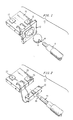
- Node 10 An exemplary information station, or node 10 formed in accordance with the present invention is illustrated in FIG. 1.
- Node 10 includes a surface-emitting LED 12 which is coupled to a multimode optical fiber 14 via a lensing element 16 such that the core region of fiber 14 is aligned with the active area of LED 12.
- LED 12 is further coupled to a transmit/receive integrated circuit 18, as shown in FIG. 1. It is to be understood that LED 12 may in fact be fabricated on the same substrate as the transmit/receive circuitry 18 so as to form a completely monolithic structure.
- surface-emitting LED 12 In its transmitting mode, surface-emitting LED 12 is connected to transmit circuitry 15 and will radiate an outgoing message signal M which passes through lens 16 and enters fiber 14.
- LED 12 is biased at zero volts (or alternatively, backbiased) and acts as a photodiode, transforming any received light signal R into an electronic equivalent. This electronic equivalent is then passed along to receive circuitry 17.
- surface-emitting LED 12 may be replaced by an edge-emitting LED.
- An exemplary information station 20 utilizing such an element is illustrated in FIG. 2.
- an edge-emitting LED 22 is coupled to a single mode fiber 24, where the end portion 26 of single mode fiber 24 is tapered to form a lensing/coupling element between edge-emitting LED 22 and single mode fiber 24.
- an integrated circuit 28 includes both the transmit circuitry 25 and receive circuitry 27, and may be further modified to include edge-emitting LED 22 as part of the monolithic structure.
- information station 20 functions in an identical manner as station 10 described above.
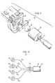
- an information station of the present invention may also utilize a semiconductor laser (and its associated backface monitor) as the lightwave transceiving element.
- a semiconductor laser 32 is connected to a single mode fiber 34 by an optical coupling device, in this particular example a silicon spherical lens 36 and a graded index (GRIN) rod lens 38 disposed in a confocal arrangement.
- a backface monitor 40 for example, a PIN photodiode, is positioned behind the rear facet of laser 32.
- An integrated circuit 42 including transmit circuitry 44 and receive circuitry 46, is illustrated in FIG. 3 as connected to both laser 32 and photodiode monitor 40.
- a local area network (LAN) formed with any of the above-described information stations may operate, for example, with the token-passing protocol.
- the operation of one such station using this type of protocol (a laser-based station) will be briefly described.
- protocol arrangements other than token passing may be used, and that the token-passing protocol is equally applicable to LED-based as well as laser-based information stations.
- a laser-based node 30 will usually be in its receiving, or listening mode, waiting for the reception of the token signal before beginning its transmission.
- incoming light signal from fiber 34 will be amplified by laser 32 and directed towards backface monitor 40.
- the output from backface monitor 40 which is an electrical signal, is subsequently transmitted to receive circuitry 46.
- the received signal may be either a received message signal R destined for node 30, or a message signal destined for another node in the network. Circuit 46 is so designed to be able to discriminate between these various signals.
- receiver circuit 46 When the token signal T is received by node 30, receiver circuit 46 will transmit a control signal C to transmit circuit 44, allowing node 30 to begin its transmission.
- control signal C causes circuit 44 to both bias laser 32 in the active mode and modulate the light output from laser 32 so as to form the broadcasted message signal M.
- transmitter circuit 44 may only activate laser 32 when the system token has been received.
- FIG. 4 illustrates an exemplary reflective star network 50 which is formed using a plurality of the nodes as described above in association with FIGs. 1, 2 or 3.
- the networks will employ laser-based information stations. However, it is to be understood that these networks may also use the LED-based stations illustrated in FIGs. 1 and 2.
- reflective star network 50 includes four information stations (hereinafter referred to as "nodes"), labeled 521, 522, 523, and 524. Each node has an associated communication fiber 541-544, respectively, exiting the node.
- Fibers 541-544 are coupled to a reflective star coupler 56, where coupler 56 comprises a lensing arrangement which is capable of receiving a lightwave signal transmitted along any of the fibers 541-544.
- coupler 56 comprises a lensing arrangement which is capable of receiving a lightwave signal transmitted along any of the fibers 541-544.
- reflective star coupler 56 includes a rear reflecting surface 58 upon which the received signal will impinge and be redistributed among all of the fibers attached to coupler 56.
- node 522 is designated as being in possession of the transmitting token T.
- node 522 transmits its message signal M2 along fiber 542 to reflective star coupler 56.
- Message signal M2 will then be redirected by reflecting surface 58 into all of the fibers 541-544 connected to coupler 56 and retransmitted (rebroadcast) into the network as a "received" signal R2 to all nodes on the network. As shown, signal R2 will also be transmitted back to node 522, which may either ignore this signal or check for errors in its broadcasted message. Once the broadcast from node 522 is completed, node 523 will receive token signal T and initiate its transmission. If this node has no information to transmit at that moment, the token will immediately be transferred to node 524, where the entire process will begin again.
- a reflective bus 60 includes a single fiber 62 coupled to a reflecting element 64, as opposed to the N fiber connection of the star configuration of FIG. 4.
- nodes designated 661-664
- fiber 682 terminates in a coupling device 70, where the remaining input to coupling device 70 is fiber 681 from node 661.
- Coupling device 70 functions to redirect message signal M2 along ouput fiber 72, where fiber 72 is subsequently applied as an input to a second coupling device 74. As shown in FIG. 5, the remaining input to second coupling device 74 is output fiber 683 from node 663. In a similar manner, second coupling device 74 functions to redirect any incoming message signal into output fiber 76. Output fiber 76, as shown, is then coupled as a first input to a third coupling device 78, where fiber 684 from node 664 is applied as the remaining input to third coupling device 78. The output from third coupling device 78 is the single fiber 62 defined above as coupled to reflecting element 64.
- message signal M2 from node 662 will pass through coupling devices 70, 74, 78 and fibers 72, 76 and 62, eventually being applied as an input to reflecting element 64.
- reflecting element 64 includes a reflecting surface 65 which merely reverses message signal M2 and redirects it (as received signal R2) back into fiber 62. Received signal R2 then travels the reverse path and is eventually received by each node 661-664.
- FIGs. 4 and 5 may both exhibit size limitations in terms of the number of nodes which may interact via a single reflecting element.
- This limitation is in reality a power budget limitation, since the power of the signal broadcast by the transmitting node must not only be sufficient to propagate back, but must also be sufficient to be divided and distributed through the transmission medium to the reflecting element and among the many nodes or receivers.
- any network with a large number of nodes would not be an appropriate candidate for either of the configurations illustrated in FIGs. 4 or 5.
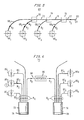
- An alternative configuration which is better suited for this type of network may be defined as a linked star network and is illustrated in FIG. 6.
- linked star network 70 of FIG. 6 overcomes the network size problem by utilizing a plurality of reflecting couplers, with linking means joining the couplers together.
- the linked star network 70 of FIG. 6 is illustrated as including only two such reflecting couplers. However, it is to be understood that any number N of such couplers could be linked together in a similar fashion.
- linked star 70 is seen to comprise a first reflecting coupler 72, with an associated reflecting surface 74, and a second reflecting coupler 76, with an associated reflecting surface 78.
- three nodes 801-803 are connected to first reflecting star 72 via their respective optical fibers 821-823.
- a set of three nodes 804-806 are connected to second reflecting star 76 via their respective optical fibers 824-826.
- a linking fiber 84 is utilized to couple first reflecting coupler 72 to second reflecting coupler 76, with a repeater 86 being inserted along fiber 84 to reshape the signal being transmitted between the couplers.
- linked star network 70 varies little from the reflective star described above in association with FIG. 4.
- node 802 will broadcast its message signal M2 which will enter first reflecting coupler 72 and be reflected into the plurality of fibers attached to first reflecting element 72, communication fibers 821-823 as well as linking fiber 84.
- message signal M2 will be received directly by nodes 801-803 and will enter repeater 86 inserted in fiber 84.
- message signal M2 will continue to propagate along linking fiber 84 and enter second reflecting coupler 76. As before, the signal will be reflected off of surface 78 and redirected into fibers 824-826 for reception by nodes 804-806.
- active star 90 of FIG. 7 comprises a plurality of nodes, designated 911-926, similar to those described above, where a plurality of fibers 941-946 exiting these nodes are coupled to a mixing rod 96.
- a reflecting surface 98 is disposed at the opposite end of mixing rod 96 and functions to redirect any incoming message signal into a photodiode 100.
- photodiode 100 will convert the incoming optical message signal into an electrical equivalent.
- This electrical equivalent is subsequently passed through a regenerator 102 and utilized to drive a laser 104.
- the regenerated message signal produced by laser 104 then propagates along a fiber 106 and reenters mixing rod 96 through reflecting surface 98.
- laser 104 operates at a different wavelength than the transceiving devices at the nodes.
- reflecting surface 98 may be a dichroic mirror which will reflect the incoming wavelength (into the photodiode) and fully pass the outgoing wavelength (from laser 104), with very little, if any, interference between the two signals.
- Another advantage to using a regenerating laser at a different wavelength is that it is possible to shift the frequency of the received message signal to a transceiver wavelength which is more efficient.
- a transceiving laser which broadcasts at 0.87 ⁇ m is not a very good photodetector at this wavelength. If laser 104 associated with active star 90 is designated to transmit at a lower frequency, 0.82 ⁇ m, for example, this will move the spectrum into an area which is a better absorber for the transceiving devices.
- a master/slave polled network 120 comprises a master node 122 and a plurality of slave nodes 1241-1244, interconnected by a 1xN splitter/combiner 126 (N being defined as the number of slave nodes connected to network 120).
- master node 122 is coupled via fiber 128 to splitter/combiner 126, where the output of splitter/combiner 126 is a plurality of fibers 1301-1304, each fiber coupled to its respective slave node 1241-1244.
- master node 122 polls slave nodes 1241-1244 one at a time, where the slave nodes respond in turn. In this particular configuration, therefore, a different message may be transmitted to each slave node.
- the linked star configuration of FIG. 6 may be replaced by a linked bus.
- the active star of FIG. 7 may be replaced by an active bus.
Landscapes
- Engineering & Computer Science (AREA)
- Physics & Mathematics (AREA)
- Electromagnetism (AREA)
- Computer Networks & Wireless Communication (AREA)
- Signal Processing (AREA)
- Computing Systems (AREA)
- Optical Communication System (AREA)
- Optical Couplings Of Light Guides (AREA)
- Led Device Packages (AREA)
- Small-Scale Networks (AREA)
- Semiconductor Lasers (AREA)
- Led Devices (AREA)
- Light Receiving Elements (AREA)
Applications Claiming Priority (2)
| Application Number | Priority Date | Filing Date | Title |
|---|---|---|---|
| US21583188A | 1988-07-06 | 1988-07-06 | |
| US215831 | 1988-07-06 |
Publications (1)
| Publication Number | Publication Date |
|---|---|
| EP0350207A2 true EP0350207A2 (fr) | 1990-01-10 |
Family
ID=22804577
Family Applications (1)
| Application Number | Title | Priority Date | Filing Date |
|---|---|---|---|
| EP89306605A Withdrawn EP0350207A2 (fr) | 1988-07-06 | 1989-06-29 | Réseau local à fibre unique basé sur des émetteurs-récepteurs |
Country Status (3)
| Country | Link |
|---|---|
| EP (1) | EP0350207A2 (fr) |
| JP (1) | JPH0265538A (fr) |
| KR (1) | KR920005215B1 (fr) |
Cited By (6)
| Publication number | Priority date | Publication date | Assignee | Title |
|---|---|---|---|---|
| EP0419710A1 (fr) * | 1989-09-28 | 1991-04-03 | Siemens Aktiengesellschaft | Système de télécommunication bidirectionnel à fibre optique à division de longueur d'onde entre un station de télécommunication central et un nombre de stations de télécommunication à distance |
| DE9111173U1 (de) * | 1991-09-09 | 1991-12-05 | AEG KABEL AG, 4050 Mönchengladbach | Anordnung zum Zusammenführen von elektrischen Hochfrequenz-Signalen |
| US5202943A (en) * | 1991-10-04 | 1993-04-13 | International Business Machines Corporation | Optoelectronic assembly with alignment member |
| US5610749A (en) * | 1994-03-09 | 1997-03-11 | Sharp Kabushiki Kaisha | Microcomputer control optical fiber transmission system |
| WO2000048340A1 (fr) * | 1999-02-12 | 2000-08-17 | Marconi Communications, Inc. | Procede et dispositif de conversion de signaux electriques en signaux optiques, destines a une communication bidirectionnelle sur une seule fibre optique |
| WO2003084102A1 (fr) * | 2002-04-03 | 2003-10-09 | Mitsubishi Denki Kabushiki Kaisha | Emetteur-recepteur de communication optique et procede permettant d'emettre/recevoir des donnees |
-
1989
- 1989-06-27 JP JP1162856A patent/JPH0265538A/ja active Pending
- 1989-06-29 EP EP89306605A patent/EP0350207A2/fr not_active Withdrawn
- 1989-07-04 KR KR1019890009449A patent/KR920005215B1/ko not_active Expired
Cited By (9)
| Publication number | Priority date | Publication date | Assignee | Title |
|---|---|---|---|---|
| EP0419710A1 (fr) * | 1989-09-28 | 1991-04-03 | Siemens Aktiengesellschaft | Système de télécommunication bidirectionnel à fibre optique à division de longueur d'onde entre un station de télécommunication central et un nombre de stations de télécommunication à distance |
| US5119223A (en) * | 1989-09-28 | 1992-06-02 | Siemens Aktiengesellschaft | Bidirectional light waveguide (LWG) telecommunication system and method for wavelength separation mode (bidirectional wavelength separation mode (WDM) between a central telecommunication location and plurality of decentralized telecommunication locations |
| DE9111173U1 (de) * | 1991-09-09 | 1991-12-05 | AEG KABEL AG, 4050 Mönchengladbach | Anordnung zum Zusammenführen von elektrischen Hochfrequenz-Signalen |
| US5202943A (en) * | 1991-10-04 | 1993-04-13 | International Business Machines Corporation | Optoelectronic assembly with alignment member |
| US5610749A (en) * | 1994-03-09 | 1997-03-11 | Sharp Kabushiki Kaisha | Microcomputer control optical fiber transmission system |
| WO2000048340A1 (fr) * | 1999-02-12 | 2000-08-17 | Marconi Communications, Inc. | Procede et dispositif de conversion de signaux electriques en signaux optiques, destines a une communication bidirectionnelle sur une seule fibre optique |
| US6535308B1 (en) | 1999-02-12 | 2003-03-18 | Marconi Communications, Inc. | Method and apparatus for converting electrical signals and optical signals for bidirectional communication over a single optical fiber |
| WO2003084102A1 (fr) * | 2002-04-03 | 2003-10-09 | Mitsubishi Denki Kabushiki Kaisha | Emetteur-recepteur de communication optique et procede permettant d'emettre/recevoir des donnees |
| CN100393006C (zh) * | 2002-04-03 | 2008-06-04 | 三菱电机株式会社 | 光通信收发机和用于收发数据的方法 |
Also Published As
| Publication number | Publication date |
|---|---|
| KR920005215B1 (ko) | 1992-06-29 |
| JPH0265538A (ja) | 1990-03-06 |
| KR900002586A (ko) | 1990-02-28 |
Similar Documents
| Publication | Publication Date | Title |
|---|---|---|
| US4712859A (en) | Distributed star network | |
| US4366565A (en) | Local area network optical fiber data communication | |
| US4781427A (en) | Active star centered fiber optic local area network | |
| US4317614A (en) | Fiber optic bus manifold | |
| US4233589A (en) | Active T-coupler for fiber optic local networks which permits collision detection | |
| JPS5899046A (ja) | 星形通信網 | |
| US4662715A (en) | Fiber optic network with reduced coupling losses | |
| JPH08317433A (ja) | 光ネットワーク内に実装される一次元の光データアレイ | |
| JPS61182347A (ja) | 光フアイバ回路網 | |
| US4551829A (en) | Wavelength division multiplexed fiber-optic cable system with non-unique terminal types | |
| EP0350207A2 (fr) | Réseau local à fibre unique basé sur des émetteurs-récepteurs | |
| US6567195B1 (en) | Optical network using remote optical powering of optoelectronic switch | |
| US5404241A (en) | Optical communication network | |
| GB2123236A (en) | Arrangement for locating faults in an optical transmission system | |
| Tamura et al. | Optical cascade star network-A new configuration for a passive distribution system with optical collision detection capability | |
| Kaminow | Photonic Multiple‐Access Networks: Topologies | |
| GB2247089A (en) | Optical fibre rotating joint with coupling lenses | |
| JPS6333810B2 (fr) | ||
| US5414785A (en) | Optical data bus having collision detection capability | |
| US4913509A (en) | Fail-safe port for use with an optical fiber | |
| US20050089332A1 (en) | Long reach optical transmission over a single fiber | |
| JP2001141967A (ja) | 光送受信装置 | |
| JP2930150B2 (ja) | 光通信ネットワーク | |
| JP3237464B2 (ja) | ループバック光通信システム | |
| JPS6253032A (ja) | 光フアイバ双方向伝送方式 |
Legal Events
| Date | Code | Title | Description |
|---|---|---|---|
| PUAI | Public reference made under article 153(3) epc to a published international application that has entered the european phase |
Free format text: ORIGINAL CODE: 0009012 |
|
| AK | Designated contracting states |
Kind code of ref document: A2 Designated state(s): DE ES FR GB NL SE |
|
| STAA | Information on the status of an ep patent application or granted ep patent |
Free format text: STATUS: THE APPLICATION HAS BEEN WITHDRAWN |
|
| 18W | Application withdrawn |
Withdrawal date: 19901207 |
|
| R18W | Application withdrawn (corrected) |
Effective date: 19901207 |