EP0350452A2 - Installation de combustion avec air-gaz-cheminée - Google Patents
Installation de combustion avec air-gaz-cheminée Download PDFInfo
- Publication number
- EP0350452A2 EP0350452A2 EP89810503A EP89810503A EP0350452A2 EP 0350452 A2 EP0350452 A2 EP 0350452A2 EP 89810503 A EP89810503 A EP 89810503A EP 89810503 A EP89810503 A EP 89810503A EP 0350452 A2 EP0350452 A2 EP 0350452A2
- Authority
- EP
- European Patent Office
- Prior art keywords
- air intake
- exhaust gas
- chimney
- air
- flow
- Prior art date
- Legal status (The legal status is an assumption and is not a legal conclusion. Google has not performed a legal analysis and makes no representation as to the accuracy of the status listed.)
- Granted
Links
Images
Classifications
-
- F—MECHANICAL ENGINEERING; LIGHTING; HEATING; WEAPONS; BLASTING
- F23—COMBUSTION APPARATUS; COMBUSTION PROCESSES
- F23L—SUPPLYING AIR OR NON-COMBUSTIBLE LIQUIDS OR GASES TO COMBUSTION APPARATUS IN GENERAL ; VALVES OR DAMPERS SPECIALLY ADAPTED FOR CONTROLLING AIR SUPPLY OR DRAUGHT IN COMBUSTION APPARATUS; INDUCING DRAUGHT IN COMBUSTION APPARATUS; TOPS FOR CHIMNEYS OR VENTILATING SHAFTS; TERMINALS FOR FLUES
- F23L3/00—Arrangements of valves or dampers before the fire
-
- F—MECHANICAL ENGINEERING; LIGHTING; HEATING; WEAPONS; BLASTING
- F23—COMBUSTION APPARATUS; COMBUSTION PROCESSES
- F23L—SUPPLYING AIR OR NON-COMBUSTIBLE LIQUIDS OR GASES TO COMBUSTION APPARATUS IN GENERAL ; VALVES OR DAMPERS SPECIALLY ADAPTED FOR CONTROLLING AIR SUPPLY OR DRAUGHT IN COMBUSTION APPARATUS; INDUCING DRAUGHT IN COMBUSTION APPARATUS; TOPS FOR CHIMNEYS OR VENTILATING SHAFTS; TERMINALS FOR FLUES
- F23L17/00—Inducing draught; Tops for chimneys or ventilating shafts; Terminals for flues
- F23L17/02—Tops for chimneys or ventilating shafts; Terminals for flues
- F23L17/04—Balanced-flue arrangements, i.e. devices which combine air inlet to combustion unit with smoke outlet
-
- F—MECHANICAL ENGINEERING; LIGHTING; HEATING; WEAPONS; BLASTING
- F24—HEATING; RANGES; VENTILATING
- F24B—DOMESTIC STOVES OR RANGES FOR SOLID FUELS; IMPLEMENTS FOR USE IN CONNECTION WITH STOVES OR RANGES
- F24B1/00—Stoves or ranges
- F24B1/18—Stoves with open fires, e.g. fireplaces
- F24B1/185—Stoves with open fires, e.g. fireplaces with air-handling means, heat exchange means, or additional provisions for convection heating ; Controlling combustion
- F24B1/189—Stoves with open fires, e.g. fireplaces with air-handling means, heat exchange means, or additional provisions for convection heating ; Controlling combustion characterised by air-handling means, i.e. of combustion-air, heated-air, or flue-gases, e.g. draught control dampers
- F24B1/19—Supplying combustion-air
-
- F—MECHANICAL ENGINEERING; LIGHTING; HEATING; WEAPONS; BLASTING
- F23—COMBUSTION APPARATUS; COMBUSTION PROCESSES
- F23J—REMOVAL OR TREATMENT OF COMBUSTION PRODUCTS OR COMBUSTION RESIDUES; FLUES
- F23J2211/00—Flue gas duct systems
- F23J2211/10—Balanced flues (combining air supply and flue gas exhaust)
- F23J2211/101—Balanced flues (combining air supply and flue gas exhaust) with coaxial duct arrangement
Definitions
- the present invention relates to a combustion system connected to an air-exhaust chimney to form a closed system and to a thin-walled chimney extension for use in such a combustion system.
- the furnace can e.g. a central heating system, a single fireplace or an open fireplace (chimney).
- LAS chimneys are chimneys in which a supply air duct runs parallel to the flue gas duct.
- the flue gas outlet and the inlet air inlets are locally separated at the chimney top, so that there is usually only a small pressure difference between these two openings in the wind. This reduces the risk of backflows, as is occasionally the case when the air inlet and outlet openings are further separated.
- the small distance between these two openings in the LAS system harbors the risk of recirculation, ie there is the major disadvantage that exhaust gas, especially in the case of wind, gets into the intake air. Depending on the influence of the wind, this can significantly impair the combustion process.
- the object of the present invention is, in particular, to create a central heating or chemo (open fireplace) firing system which is connected to a LAS chimney to form a closed firing system, in which this highly undesirable recirculation is avoided entirely, or at least up to now, even in the most extreme wind conditions acceptable level is reduced very much.
- chemo open fireplace
- a regulating member regulating the air intake volume flow is arranged in the air intake duct, and the latter is connected for regulating it to at least one exhaust gas or supply air sensor arranged in the exhaust duct and / or air intake duct.
- the at least one sensor can be designed, for example, to be responsive to the parameters prevailing in the exhaust gas flow, such as pressure and / or temperature and / or lambda number and / or flow velocity. The actual value determined is then compared in a comparison circuit with the corresponding target values and any difference for controlling this regulating element is evaluated.
- the exhaust gas outlet opening is dimensioned such that the exhaust gas outlet speed is at least 1.4 m / s, preferably at least 1.9 m / s.
- the present invention furthermore relates to a thin-walled chimney extension for use in a combustion system according to claim 1, with flow guiding elements projecting beyond and laterally distancing the exhaust outlet opening, a flow separating plate arranged at least 200 mm below the exhaust outlet opening and above at least one air suction opening and extending outward in the horizontal direction, a central exhaust duct and an air intake duct arranged concentrically to the latter and connected to the air intake opening.
- the flow guide elements are arranged at least approximately in at least one round and / or polygonal, preferably octagonal truncated cone and / or cylindrical surface, and these flow guide surfaces are preferably at least partially provided with throughflow openings.
- Chimney hats or flow control elements of this type are, for example, from AT-PS 375 455, CH-PS 350 063, PCT publication WO 86 / O6818, CH-PS (CH-application number 2047 / 87-2) or CH-PS (CH application no. 2103 / 87-3) is known.
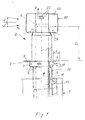
- the chimney extension 3 a so-called chimney hat, of a so-called thin-walled, sheet metal material stabilizing the outflow conditions in the most varied of wind inflow conditions, is superior in the case of the fireplace system 2 connected to a LAS chimney to form a closed firing system and laterally spacedly surrounding exhaust gas outlet opening 4 by a distance D, which in the present case is 200 mm, is arranged above a plurality of air intake openings 6 covered by a flow separating plate 5. Furthermore, the exhaust gas outlet opening 4 is designed and dimensioned such that the exhaust gas outlet velocity V is at least 0.5 m / s.
- the air intake openings 6 are adjusted with regard to the size of their opening cross section bar or the entire air intake part 7 can be adjusted slightly downwards along the outer tube 8, so that an annular suction gap 9 (dash-dotted line) is additionally drawn in below the flow separating plate 5 between the underside thereof and the upper edge of the annularly shaped air intake part 7.
- the air intake duct 11 thermally insulated from the exhaust duct 13 by means of an insulation layer 12.
- the flow separating plate 5 projects beyond the air intake openings 6 in the horizontal direction by at least 20 mm.
- a regulating member 14 which can regulate the flow of the air intake volumetric flow, is arranged in the lower end region of the air intake duct 11, which can be in the form of an iris diaphragm, a slide valve and / or a blower, for example .
- at least one exhaust gas sensor 15 is arranged in the exhaust gas duct 13 and is designed to determine exhaust gas parameters of interest in the exhaust gas flow, such as pressure and / or temperature and / or lambda number and / or flow velocity and / or the chimney temperature.
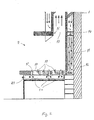
- the actual values determined in this way are compared in a comparison and evaluation circuit connected to the sensors 15 and 16 with the target values required for an optimal combustion process, and any differences for the control of the regulating member 14 are evaluated.
- the firing surface 17 of the fireplace 2 is chamber-shaped and this chamber 18 is connected to the lower end of the air intake duct 11.
- the top of this chamber 18, i.e. the firing surface 17 of the fireplace 2 is provided with air outlet openings 19, through which the supply air regulated via the LAS chimney 1 is supplied to the fireplace.
- the tubular passage openings 20 provided in the chamber 18 and closable at their upper ends serve to discharge the ashes accumulating on the firing surface 17 into a dustproof ash container 21 which is slidably and removably arranged below the chamber 18.
- the comparison and evaluation circuit connected to the sensors 15 and 16 can also be designed to be programmable in such a way that the regulating member 14 is regulated according to a different law when the fireplace 2 is started up than after the normal operating temperature has been reached.
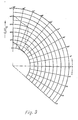
- curves represent measured recirculation values, curve A showing the exhaust gas recirculation behavior with an arrangement according to FIG. 1, but without the thin-walled chimney extension 21 and curve B showing the exhaust gas recirculation behavior with an arrangement according to FIG. 1, these curves representing measured values .
- the thin-walled chimney extension 21 was designed in accordance with PCT publication WO 86 / O6818, i.e. a chimney cap of the type Basten-Regulator-Extra from Inventina AG., Landquart (Switzerland) was used.
- the exhaust gas recirculation can be drastically reduced so far completely unexpectedly for the person skilled in the art when using the arrangement designed according to the invention, as is clearly and unambiguously evident with the aid of curve B.
- the air intake duct 11 required for the combustion process can also be used the amount of air to be supplied per unit of time / unit of time and thus of course the amount of warm exhaust gas (unit of time) to be discharged via the chimney 1 are reduced accordingly, which results in better thermal efficiency of the combustion system.
- the additional use of the supply air regulator 14 allows the combustion process in the furnace to be further stabilized and optimized.
Landscapes
- Engineering & Computer Science (AREA)
- Chemical & Material Sciences (AREA)
- Combustion & Propulsion (AREA)
- Mechanical Engineering (AREA)
- General Engineering & Computer Science (AREA)
- Chimneys And Flues (AREA)
- Incineration Of Waste (AREA)
Applications Claiming Priority (2)
| Application Number | Priority Date | Filing Date | Title |
|---|---|---|---|
| CH2538/88 | 1988-07-04 | ||
| CH2538/88A CH678223A5 (fr) | 1988-07-04 | 1988-07-04 |
Publications (3)
| Publication Number | Publication Date |
|---|---|
| EP0350452A2 true EP0350452A2 (fr) | 1990-01-10 |
| EP0350452A3 EP0350452A3 (fr) | 1991-03-27 |
| EP0350452B1 EP0350452B1 (fr) | 1995-01-18 |
Family
ID=4236047
Family Applications (1)
| Application Number | Title | Priority Date | Filing Date |
|---|---|---|---|
| EP89810503A Expired - Lifetime EP0350452B1 (fr) | 1988-07-04 | 1989-07-04 | Installation de combustion avec air-gaz-cheminée |
Country Status (4)
| Country | Link |
|---|---|
| EP (1) | EP0350452B1 (fr) |
| AT (1) | ATE117421T1 (fr) |
| CH (1) | CH678223A5 (fr) |
| DE (1) | DE58908899D1 (fr) |
Cited By (3)
| Publication number | Priority date | Publication date | Assignee | Title |
|---|---|---|---|---|
| FR2851324A1 (fr) * | 2003-02-19 | 2004-08-20 | Participation Gestion Dev Ind | Conduit terminal pour conduit de cheminee a double paroi |
| EP2530380A1 (fr) * | 2011-06-01 | 2012-12-05 | Poujoulat | Installation de chauffage comprenant un appareil de chauffage à bois, une sortie de bâtiment et un conduit de liaison |
| CN108507345A (zh) * | 2018-03-15 | 2018-09-07 | 杨支钢 | 一种带平衡窗的排烟管 |
Families Citing this family (1)
| Publication number | Priority date | Publication date | Assignee | Title |
|---|---|---|---|---|
| CN103047686B (zh) * | 2013-01-17 | 2016-02-10 | 黄爱国 | 生物质燃烧炉及进气方法 |
Family Cites Families (6)
| Publication number | Priority date | Publication date | Assignee | Title |
|---|---|---|---|---|
| DK108194C (da) * | 1960-07-06 | 1967-10-09 | Sten Wilhelm Larsvall | Opvarmningsanlæg for beboelsesejendomme og lignende bygninger. |
| DE2337615A1 (de) * | 1973-07-24 | 1974-02-07 | Jetmaster Pty | Heizvorrichtung, insbesondere kamin oder feuerstelle fuer wohnraeume |
| US4141336A (en) * | 1977-01-27 | 1979-02-27 | Fitch John C | Fireplace stove |
| US4262608A (en) * | 1979-06-14 | 1981-04-21 | Jackson Bert W | Method and apparatus for powered flue products exhaust and preheated combustion air supply |
| DE3435902A1 (de) * | 1984-09-29 | 1986-04-10 | Brown, Boveri & Cie Ag, 6800 Mannheim | Anordnung zum selbsttaetigen regeln des luftueberschusses einer verbrennung |
| AT387842B (de) * | 1985-05-14 | 1989-03-28 | Hefel Herbert | Schornsteinaufsatz |
-
1988
- 1988-07-04 CH CH2538/88A patent/CH678223A5/de not_active IP Right Cessation
-
1989
- 1989-07-04 DE DE58908899T patent/DE58908899D1/de not_active Expired - Fee Related
- 1989-07-04 AT AT89810503T patent/ATE117421T1/de not_active IP Right Cessation
- 1989-07-04 EP EP89810503A patent/EP0350452B1/fr not_active Expired - Lifetime
Cited By (5)
| Publication number | Priority date | Publication date | Assignee | Title |
|---|---|---|---|---|
| FR2851324A1 (fr) * | 2003-02-19 | 2004-08-20 | Participation Gestion Dev Ind | Conduit terminal pour conduit de cheminee a double paroi |
| EP1450101A1 (fr) * | 2003-02-19 | 2004-08-25 | Participation Gestion Développement Industriel - P.G.D.I.-S.A. | Conduit terminal pour conduit de cheminée à double paroi |
| EP2530380A1 (fr) * | 2011-06-01 | 2012-12-05 | Poujoulat | Installation de chauffage comprenant un appareil de chauffage à bois, une sortie de bâtiment et un conduit de liaison |
| FR2976050A1 (fr) * | 2011-06-01 | 2012-12-07 | Poujoulat | Installation de chauffage comprenant un appareil de chauffage a bois, une sortie de batiment et un conduit de liaison |
| CN108507345A (zh) * | 2018-03-15 | 2018-09-07 | 杨支钢 | 一种带平衡窗的排烟管 |
Also Published As
| Publication number | Publication date |
|---|---|
| DE58908899D1 (de) | 1995-03-02 |
| EP0350452A3 (fr) | 1991-03-27 |
| EP0350452B1 (fr) | 1995-01-18 |
| ATE117421T1 (de) | 1995-02-15 |
| CH678223A5 (fr) | 1991-08-15 |
Similar Documents
| Publication | Publication Date | Title |
|---|---|---|
| EP0036126B1 (fr) | Dispositif de réglage de l'écoulement d'air de combustion pour consommateurs de gaz de combustion | |
| EP0062854B1 (fr) | Dispositif de chauffage à gaz pour eau ou air | |
| DE102006062082B4 (de) | Zuluftvorrichtung und Verfahren zur Regelung der Luftströmungsmenge | |
| DE2545135C2 (fr) | ||
| EP0350452A2 (fr) | Installation de combustion avec air-gaz-cheminée | |
| DE19543018A1 (de) | Gasregeleinrichtung für einen Gasbrenner und Gasdüse hierfür | |
| DE3879124T2 (de) | Erhitzer. | |
| DE2429501A1 (de) | Vorrichtung zur regulierung der dem brenner eines gasdichten heizkessels mit kuenstlichem abzug zugefuehrten luftmenge | |
| DE19509746B4 (de) | Backofen | |
| EP1305553B1 (fr) | Systeme de combustion pour un appareil de cuisson et appareil de cuisson pourvu d'un tel systeme de combustion | |
| EP3460330A1 (fr) | Dispositif de mélange pour un appareil de chauffage et appareil de chauffage doté d'un tel dispositif de mélange | |
| DE1930972A1 (de) | Schornstein mit Zugregelung | |
| DE3306455A1 (de) | Verfahren und vorrichtung zur verringerung der staubbelastung der raumluft | |
| DE659099C (de) | Vorrichtung zur Feststellung der Faerbung von Verbrennungsgasen | |
| DE4010134A1 (de) | Luftzufuehrungsvorrichtung fuer die raumklimatisierung | |
| DE69828211T2 (de) | Belüftungseinheit | |
| DE2715835C2 (de) | Steuerungsanordnung für Klimaanlagen mit variablem Zuluft-Volumen | |
| AT404874B (de) | Sekundärluftsteuervorrichtung für eine heizeinrichtung | |
| DE1900762U (de) | Lueftungseinrichtung zur lueftung von raeumen in gebaeuden, insbesondere staellen. | |
| DE68906527T2 (de) | Luftverteilungsverfahren und vorrichtung dazu. | |
| AT212535B (de) | Vorrichtung zur Regelung der Verbrennung im Feuerraum eines mit flüssigem oder gasförmigem Brennstoff betriebenen Heizgerätes | |
| DE945789C (de) | Vorrichtung fuer die Mengenregelung stroemender Medien | |
| AT217185B (de) | Vorrichtung zur Regulierung der Verbrennung im Feuerraum eines Heizapparates | |
| DE1940680A1 (de) | Verfahren und Vorrichtung zum Verhindern der Versottung von Schornsteinen | |
| CH720474A1 (de) | Lüftungssystem enthaltend eine Druckprüfung |
Legal Events
| Date | Code | Title | Description |
|---|---|---|---|
| PUAI | Public reference made under article 153(3) epc to a published international application that has entered the european phase |
Free format text: ORIGINAL CODE: 0009012 |
|
| AK | Designated contracting states |
Kind code of ref document: A2 Designated state(s): AT BE DE FR GB NL SE |
|
| PUAL | Search report despatched |
Free format text: ORIGINAL CODE: 0009013 |
|
| AK | Designated contracting states |
Kind code of ref document: A3 Designated state(s): AT BE DE FR GB NL SE |
|
| 17P | Request for examination filed |
Effective date: 19910914 |
|
| 17Q | First examination report despatched |
Effective date: 19920117 |
|
| GRAA | (expected) grant |
Free format text: ORIGINAL CODE: 0009210 |
|
| AK | Designated contracting states |
Kind code of ref document: B1 Designated state(s): AT BE DE FR GB NL SE |
|
| REF | Corresponds to: |
Ref document number: 117421 Country of ref document: AT Date of ref document: 19950215 Kind code of ref document: T |
|
| REF | Corresponds to: |
Ref document number: 58908899 Country of ref document: DE Date of ref document: 19950302 |
|
| RAP2 | Party data changed (patent owner data changed or rights of a patent transferred) |
Owner name: PVA-PATENTVERWERTUNGSGESELLSCHAFT |
|
| PG25 | Lapsed in a contracting state [announced via postgrant information from national office to epo] |
Ref country code: SE Effective date: 19950418 |
|
| ET | Fr: translation filed | ||
| PGFP | Annual fee paid to national office [announced via postgrant information from national office to epo] |
Ref country code: FR Payment date: 19950529 Year of fee payment: 7 |
|
| GBT | Gb: translation of ep patent filed (gb section 77(6)(a)/1977) |
Effective date: 19950427 |
|
| PGFP | Annual fee paid to national office [announced via postgrant information from national office to epo] |
Ref country code: GB Payment date: 19950623 Year of fee payment: 7 |
|
| PGFP | Annual fee paid to national office [announced via postgrant information from national office to epo] |
Ref country code: NL Payment date: 19950731 Year of fee payment: 7 |
|
| PLBE | No opposition filed within time limit |
Free format text: ORIGINAL CODE: 0009261 |
|
| PGFP | Annual fee paid to national office [announced via postgrant information from national office to epo] |
Ref country code: BE Payment date: 19951120 Year of fee payment: 7 |
|
| 26N | No opposition filed | ||
| PG25 | Lapsed in a contracting state [announced via postgrant information from national office to epo] |
Ref country code: GB Effective date: 19960704 |
|
| PG25 | Lapsed in a contracting state [announced via postgrant information from national office to epo] |
Ref country code: BE Effective date: 19960731 |
|
| BERE | Be: lapsed |
Owner name: PVA-PATENTVERWERTUNGSGESELLSCHAFT Effective date: 19960731 |
|
| PG25 | Lapsed in a contracting state [announced via postgrant information from national office to epo] |
Ref country code: NL Effective date: 19970201 |
|
| GBPC | Gb: european patent ceased through non-payment of renewal fee |
Effective date: 19960704 |
|
| PG25 | Lapsed in a contracting state [announced via postgrant information from national office to epo] |
Ref country code: FR Effective date: 19970328 |
|
| NLV4 | Nl: lapsed or anulled due to non-payment of the annual fee |
Effective date: 19970201 |
|
| REG | Reference to a national code |
Ref country code: FR Ref legal event code: ST |
|
| PGFP | Annual fee paid to national office [announced via postgrant information from national office to epo] |
Ref country code: DE Payment date: 19970822 Year of fee payment: 9 |
|
| PGFP | Annual fee paid to national office [announced via postgrant information from national office to epo] |
Ref country code: AT Payment date: 19971205 Year of fee payment: 9 |
|
| PG25 | Lapsed in a contracting state [announced via postgrant information from national office to epo] |
Ref country code: AT Free format text: LAPSE BECAUSE OF NON-PAYMENT OF DUE FEES Effective date: 19980704 |
|
| PG25 | Lapsed in a contracting state [announced via postgrant information from national office to epo] |
Ref country code: DE Free format text: LAPSE BECAUSE OF NON-PAYMENT OF DUE FEES Effective date: 19990501 |