EP0350783A2 - Dispositif pour actionner les consommateurs raccordés au réseau de bord de courant continue d'une unité mobile - Google Patents
Dispositif pour actionner les consommateurs raccordés au réseau de bord de courant continue d'une unité mobile Download PDFInfo
- Publication number
- EP0350783A2 EP0350783A2 EP89112327A EP89112327A EP0350783A2 EP 0350783 A2 EP0350783 A2 EP 0350783A2 EP 89112327 A EP89112327 A EP 89112327A EP 89112327 A EP89112327 A EP 89112327A EP 0350783 A2 EP0350783 A2 EP 0350783A2
- Authority
- EP
- European Patent Office
- Prior art keywords
- interference suppression
- choke
- electrical system
- pulse
- iron powder
- Prior art date
- Legal status (The legal status is an assumption and is not a legal conclusion. Google has not performed a legal analysis and makes no representation as to the accuracy of the status listed.)
- Withdrawn
Links
Images
Classifications
-
- B—PERFORMING OPERATIONS; TRANSPORTING
- B60—VEHICLES IN GENERAL
- B60H—ARRANGEMENTS OF HEATING, COOLING, VENTILATING OR OTHER AIR-TREATING DEVICES SPECIALLY ADAPTED FOR PASSENGER OR GOODS SPACES OF VEHICLES
- B60H1/00—Heating, cooling or ventilating devices
- B60H1/00421—Driving arrangements for parts of a vehicle air-conditioning
- B60H1/00428—Driving arrangements for parts of a vehicle air-conditioning electric
-
- B—PERFORMING OPERATIONS; TRANSPORTING
- B60—VEHICLES IN GENERAL
- B60R—VEHICLES, VEHICLE FITTINGS, OR VEHICLE PARTS, NOT OTHERWISE PROVIDED FOR
- B60R16/00—Electric or fluid circuits specially adapted for vehicles and not otherwise provided for; Arrangement of elements of electric or fluid circuits specially adapted for vehicles and not otherwise provided for
- B60R16/02—Electric or fluid circuits specially adapted for vehicles and not otherwise provided for; Arrangement of elements of electric or fluid circuits specially adapted for vehicles and not otherwise provided for electric constitutive elements
- B60R16/03—Electric or fluid circuits specially adapted for vehicles and not otherwise provided for; Arrangement of elements of electric or fluid circuits specially adapted for vehicles and not otherwise provided for electric constitutive elements for supply of electrical power to vehicle subsystems or for
- B60R16/0315—Electric or fluid circuits specially adapted for vehicles and not otherwise provided for; Arrangement of elements of electric or fluid circuits specially adapted for vehicles and not otherwise provided for electric constitutive elements for supply of electrical power to vehicle subsystems or for using multiplexing techniques
-
- Y—GENERAL TAGGING OF NEW TECHNOLOGICAL DEVELOPMENTS; GENERAL TAGGING OF CROSS-SECTIONAL TECHNOLOGIES SPANNING OVER SEVERAL SECTIONS OF THE IPC; TECHNICAL SUBJECTS COVERED BY FORMER USPC CROSS-REFERENCE ART COLLECTIONS [XRACs] AND DIGESTS
- Y02—TECHNOLOGIES OR APPLICATIONS FOR MITIGATION OR ADAPTATION AGAINST CLIMATE CHANGE
- Y02T—CLIMATE CHANGE MITIGATION TECHNOLOGIES RELATED TO TRANSPORTATION
- Y02T10/00—Road transport of goods or passengers
- Y02T10/80—Technologies aiming to reduce greenhouse gasses emissions common to all road transportation technologies
- Y02T10/88—Optimized components or subsystems, e.g. lighting, actively controlled glasses
-
- Y—GENERAL TAGGING OF NEW TECHNOLOGICAL DEVELOPMENTS; GENERAL TAGGING OF CROSS-SECTIONAL TECHNOLOGIES SPANNING OVER SEVERAL SECTIONS OF THE IPC; TECHNICAL SUBJECTS COVERED BY FORMER USPC CROSS-REFERENCE ART COLLECTIONS [XRACs] AND DIGESTS
- Y10—TECHNICAL SUBJECTS COVERED BY FORMER USPC
- Y10S—TECHNICAL SUBJECTS COVERED BY FORMER USPC CROSS-REFERENCE ART COLLECTIONS [XRACs] AND DIGESTS
- Y10S323/00—Electricity: power supply or regulation systems
- Y10S323/908—Inrush current limiters
Definitions
- the invention is based on a device according to the preamble of claim 1.
- the invention is therefore based on the object of providing a device for operating high-power consumers connected to the on-board network of mobile units, especially motor vehicles, which on the one hand limits the current draw from the on-board network to the values required for the actual operation of the consumer , but on the other hand ensures that this does not result in a pulse load on the vehicle electrical system, even if, in the pulse width control provided here, the supply voltage for the consumer is switched with any desired, even high frequency.
- the invention solves this problem with the characterizing features of the main claim and has the front part that a practically loss-free power control of the on-board network of motor vehicles u.
- Connected motors, especially fan motors is possible, even if they work with currents that can be up to 10 amperes, possibly even more (20 amperes and more).
- the supply voltage to the (fan) motor is therefore suddenly switched on and off again via a semiconductor switching element (preferably a MOS-FET) connected in series with the motor, with a comparatively high frequency (10 kHz and above, if desired and cheap in the practical embodiment), the respective power output of the connected motor being determined from the ratio of the pulse pause to the pulse duration, that is to say the pulse duty factor of the actuating rectangular pulse train of the supply voltage (or of the supply current).
- a semiconductor switching element preferably a MOS-FET
- the particular advantage of the present invention lies in the fact that the interference suppression circuit associated with such control electronics is capable of absorbing considerable pulse strokes with very steep flanks and preventing pulse peaks from being transferred to the general on-board electrical system, namely by having a control electronics Suppressor choke is in series, which preferably has an iron powder core as a toroidal core choke, which ensures that the choke does not saturate under normal operating currents, preferably at least 50% of the inductance as a reserve Pulse damping are available.
- Such a special iron powder toroidal choke (typical data, for example, 40 ⁇ H, 20 A) has a good frequency response due to this iron powder core, so it can dampen frequencies and has a "saturation reserve", which ensures that even at maximum operating current in the switch-on phase of the Series semiconductor switch to the motor, the hysteresis curve determining the saturation behavior is only about half extended, i.e. a considerable inductance reserve remains available for damping the high switch-on and switch-off edges resulting from the pulse width control, so that, in conjunction with other capacitors, a previously unachievable level of interference suppression such a motor control results.
- the invention therefore makes it possible, for the first time, to control fan motors or other motors which draw high currents from the vehicle electrical system to which they are connected, with a pulse width control with current-controlled specification, and at the same time not to burden the vehicle electrical system with emerging pulse peaks and, moreover, the current draw from the vehicle electrical system without having to accept high power losses to the values that are effectively required for the operation of the connected motor.
- the invention therefore makes ballast resistors or other, energy in the form of power dissipation elements are completely unnecessary and is also easy and inexpensive to manufacture in terms of control electronics, since apart from the area of the series power semiconductor switching element, the components that are otherwise used can be integrated as desired.
- the spatial arrangement of the capacitors which are also required for interference suppression plays a role, in conjunction with a closed metal housing used in a continuous development of the present invention, which both the Interference suppression circuit as well as the control electronics and realizes the other connection points for the interference suppression capacitors with its own ground connection in a geometric distribution.
- the basic idea of the present invention is, in combination with a pulse width control by means of the clocked supply voltage guaranteed thereby, to set a connected consumer, which is hereinafter referred to exclusively, but not in a restrictive manner, as a fan motor, to different performance data and to design an associated interference suppression circuit so that the in Connection with capacitors of high capacitance, the series choke which forms the interference suppression circuit contains an iron powder core (not ferrite core) and is designed in such a way that a considerable inductance reserve is available for pulse damping even when the maximum operating current is applied.
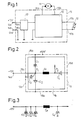
- control electronics comprise an electronic switch connected in series with the consumer 11, preferably in the form of a fan motor, which, as will be explained further below with reference to the illustration in FIG. 4, is switched from its conductive to its non-conductive state by rapid pulsed activation is switched.
- the control electronics comprise an electronic switch connected in series with the consumer 11, preferably in the form of a fan motor, which, as will be explained further below with reference to the illustration in FIG. 4, is switched from its conductive to its non-conductive state by rapid pulsed activation is switched.
- the control electronics comprise an electronic switch connected in series with the consumer 11, preferably in the form of a fan motor, which, as will be explained further below with reference to the illustration in FIG. 4, is switched from its conductive to its non-conductive state by rapid pulsed activation is switched.
- the control electronics comprise an electronic switch connected in series with the consumer 11, preferably in the form of a fan motor, which, as will be explained further below with reference to the illustration in FIG. 4, is switched from its conductive to its non-conductive state by rapid pulsed activation
- the different pulse duty factor is set with the aid of an arrangement 12 for specifying the setpoint value, which is usually a potentiometer or rotary resistor, which, practically without loss of power, feeds a comparator only a reference potential, from which the desired pulse duty factor of the supply voltage is then derived Rectangular pulse sequence results.
- an arrangement 12 for specifying the setpoint value which is usually a potentiometer or rotary resistor, which, practically without loss of power, feeds a comparator only a reference potential, from which the desired pulse duty factor of the supply voltage is then derived Rectangular pulse sequence results.
- Both circuits are located within a closed metal housing 15, which preferably consists of copper and accommodates an electronic circuit board or circuit board on the inside, on which the respective components of the control electronics or the interference suppression circuit are constructed.
- connection connections 16a, 16b for the controlled fan motor, the two signal lines 17a, 17b for the setpoint specification and of course the two input connections 18a, 18b leading to the vehicle electrical system connections are routed to the outside.
- the electrical-spatial structure of the control electronics / interference suppression circuit is preferably made as shown in FIG. 2, whereby in addition to the type and the electrical characteristic values, the mechanical position of the interference suppression components is also of considerable importance here. 2 shows the electronics board 19 located within the closed metal housing 15; the interference suppressors are on it sel Dr, preferably in the form of a ring core choke and four capacitors C1, C2 and C3, which are connected together with the one connection of the ring core choke Dr to the input connecting line 18a from the positive vehicle electrical system connection (+12 V).
- the capacitor C3 is connected with its other connection to the front wall 15c of the metal housing 15, while the fourth capacitor C4 is connected with its one connection to the opposite connection of the inductor Dr, thereby forming the circuit point P2, and with its other connection to the other free, last side wall 15d of the metal housing 15 abuts and is soldered to it.
- FIG. 3 shows the electrical circuit of the interference suppression elements from toroidal core choke Dr and the four capacitors C1, C2, C3 and C4, the capacitors being able to have the following values, for example: C1, C2 300 ⁇ F C3 150 ⁇ F C4 470 ⁇ F.
- These high capacities are useful for effective interference suppression and are also appropriate in connection with the toroidal choke used, and, as already mentioned, this toroidal core choke has a special iron powder core.
- the toroidal choke can have an inductance of 40 ⁇ H at 20 A, the iron powder core used ensuring that, in contrast to the known ferrite cores With the very high currents that occur here, magnetic supersaturation does not immediately occur, but an effective inductance reserve is kept available for interference suppression, i.e.
- the toroidal inductor has a hysteresis shape which, at maximum operating currents, still has at least 50% residual inductance, for example provides for pulse damping; it can therefore in no way be driven into saturation by the maximum currents characteristic of the respective connected consumer.
- the iron powder used should only have a very small grain size (in the range between about 4 - 5 ⁇ ) in order to be able to attenuate very high frequencies very effectively, with the binder used must insulate the individual iron powder granules as well as possible to prevent higher eddy current losses. Due to the iron powder used in a suitable binder combination, the desired magnetic behavior results that the toroidal choke cannot be magnetized into saturation by the operating current, but has the desired reserve for pulse damping.
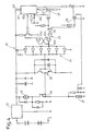
- control electronics which is only given by way of example in FIG. 4, can first be seen in an integrated switching module 20 which has a square-wave pulse sequence at its one output 20a and another output 20b at another generates a triangular voltage synchronous to this.
- the triangular voltage reaches one input of an operational amplifier 21 and is compared there with a voltage level which can be shifted in height.
- switching points are obtained which are connected via downstream circuit elements in the form of inverters connected or coupled to one another or NAND gates 23 at the input 24a of a driver stage 24 (consisting of a plurality of inverter / amplifiers connected in parallel)
- a driver stage 24 Consisting of a plurality of inverter / amplifiers connected in parallel
- generate a rectangular pulse control sequence which finally controls the semiconductor switching element 26 in the form of a MOS-FET via a downstream push-pull amplifier circuit 25, which is in series with the motor windings of the fan motor 11 '.
- a current feedback which comprises a current sensor 27 in series with the fan motor 11 'and the MOS-FET 26 in the form of a low-resistance resistor, the output voltage of which is fed back via an operational amplifier 28 to the one input of a NAND gate 29 whose other input is the output voltage resulting from the comparison of the triangular voltage and the reference voltage level Switching points of the operational amplifier 21 are supplied. This results in a control (and limitation) of the current drawn by the fan motor.
Landscapes
- Physics & Mathematics (AREA)
- Thermal Sciences (AREA)
- Engineering & Computer Science (AREA)
- Mechanical Engineering (AREA)
- Control Of Ac Motors In General (AREA)
- Control Of Electric Motors In General (AREA)
Applications Claiming Priority (2)
| Application Number | Priority Date | Filing Date | Title |
|---|---|---|---|
| DE3823778 | 1988-07-14 | ||
| DE3823778A DE3823778A1 (de) | 1988-07-14 | 1988-07-14 | Vorrichtung zum betrieb von an das bordnetz von mobilen einheiten angeschlossenen verbrauchern |
Publications (2)
| Publication Number | Publication Date |
|---|---|
| EP0350783A2 true EP0350783A2 (fr) | 1990-01-17 |
| EP0350783A3 EP0350783A3 (fr) | 1991-10-16 |
Family
ID=6358604
Family Applications (1)
| Application Number | Title | Priority Date | Filing Date |
|---|---|---|---|
| EP19890112327 Withdrawn EP0350783A3 (fr) | 1988-07-14 | 1989-07-06 | Dispositif pour actionner les consommateurs raccordés au réseau de bord de courant continue d'une unité mobile |
Country Status (3)
| Country | Link |
|---|---|
| US (1) | US5103147A (fr) |
| EP (1) | EP0350783A3 (fr) |
| DE (1) | DE3823778A1 (fr) |
Cited By (3)
| Publication number | Priority date | Publication date | Assignee | Title |
|---|---|---|---|---|
| EP0552487A3 (en) * | 1992-01-22 | 1995-04-12 | Bosch Gmbh Robert | Electronic control system for a electromagnetic actuator in a vehicle with a control device |
| EP0764567A3 (fr) * | 1995-09-20 | 1997-08-13 | Ford Werke Ag | Dispositif essuie-glace/lave-glace pour véhicules |
| WO1999005780A1 (fr) * | 1997-07-25 | 1999-02-04 | Robert Bosch Gmbh | Circuit de commande pour moteur a courant continu |
Families Citing this family (10)
| Publication number | Priority date | Publication date | Assignee | Title |
|---|---|---|---|---|
| DE4314056C2 (de) * | 1993-04-29 | 1998-05-28 | Bayerische Motoren Werke Ag | Schaltanordnung zum Herstellen einer oberwellenfreien Spannung aus der Bordnetzspannung von Kraftfahrzeugen |
| DE4444492A1 (de) * | 1994-12-14 | 1996-06-27 | Telefunken Microelectron | Steuerung der Drehzahl von Gleichstrommotoren durch getaktete Ansteuerung |
| US5661390A (en) * | 1995-06-23 | 1997-08-26 | Electric Power Research Institute, Inc. | Inverter-fed motor drive with EMI suppression |
| DE19724570A1 (de) * | 1997-06-11 | 1998-12-17 | Bayerische Motoren Werke Ag | Vorrichtung zur Stromversorgung elektrischer Hochleistungs-Verbraucher in Kraftfahrzeugen |
| FR2771866B1 (fr) * | 1997-12-03 | 2000-02-11 | Ecia Equip Composants Ind Auto | Systeme de commande de l'alimentation d'un moteur electrique d'activation d'un organe fonctionnel de vehicule automobile |
| FR2780548B1 (fr) * | 1998-06-29 | 2001-02-23 | Alsthom Gec | Ensemble d'alimentation electrique d'une charge a partir d'une source d'energie et locomotive equipee d'un tel ensemble |
| DE10049668A1 (de) * | 2000-10-06 | 2002-05-16 | Siemens Ag | Schaltungsanordnung zur Entstörung von Geräten mit stark schwankender Stromaufnahme |
| US8908350B2 (en) * | 2008-06-25 | 2014-12-09 | Core Wireless Licensing S.A.R.L. | Capacitor |
| DE102015226177A1 (de) * | 2015-12-21 | 2017-06-22 | Robert Bosch Gmbh | Entstörvorrichtung, elektronische Baugruppe und Verwendung einer Entstörvorrichtung |
| US10069448B2 (en) | 2016-06-10 | 2018-09-04 | Denso International America, Inc. | HVAC actuator |
Family Cites Families (13)
| Publication number | Priority date | Publication date | Assignee | Title |
|---|---|---|---|---|
| US4010401A (en) * | 1970-12-13 | 1977-03-01 | Matsushita Electric Industrial Co., Ltd. | Constant-voltage converter having beam current detector |
| US4017745A (en) * | 1976-02-11 | 1977-04-12 | American Laser Corporation | Switching regulator power supply |
| JPS5416664A (en) * | 1977-06-08 | 1979-02-07 | Nippon Kinzoku Co Ltd | Reactor |
| DE2813110A1 (de) * | 1978-03-25 | 1979-09-27 | Metabowerke Kg | Elektromotorisch angetriebenes geraet mit funkentstoerung |
| DE3106424A1 (de) * | 1981-02-20 | 1982-09-09 | Siemens AG, 1000 Berlin und 8000 München | Funkstoerfilter |
| US4504896A (en) * | 1981-03-18 | 1985-03-12 | Rca Corporation | Switching dc-to-dc converters |
| US4459537A (en) * | 1982-11-22 | 1984-07-10 | General Motors Corporation | Up-down voltage regulator |
| US4536700A (en) * | 1984-03-28 | 1985-08-20 | United Technologies Corporation | Boost feedforward pulse width modulation regulator |
| US4626766A (en) * | 1984-07-13 | 1986-12-02 | Siemens Aktiengesellschaft | Circuit arrangement for feeding electrical users |
| NL8500154A (nl) * | 1985-01-22 | 1986-08-18 | Koninkl Philips Electronics Nv | Zelf-oscillerende voedingsschakeling. |
| US4761722A (en) * | 1987-04-09 | 1988-08-02 | Rca Corporation | Switching regulator with rapid transient response |
| JPH0813171B2 (ja) * | 1987-06-26 | 1996-02-07 | 株式会社ユタカ電機製作所 | 安定化電源装置 |
| DE3727498A1 (de) * | 1987-08-18 | 1989-03-02 | Hella Kg Hueck & Co | Vorrichtung zum steuern der leistung eines elektrischen verbrauchers |
-
1988
- 1988-07-14 DE DE3823778A patent/DE3823778A1/de not_active Withdrawn
-
1989
- 1989-07-05 US US07/375,775 patent/US5103147A/en not_active Expired - Fee Related
- 1989-07-06 EP EP19890112327 patent/EP0350783A3/fr not_active Withdrawn
Cited By (4)
| Publication number | Priority date | Publication date | Assignee | Title |
|---|---|---|---|---|
| EP0552487A3 (en) * | 1992-01-22 | 1995-04-12 | Bosch Gmbh Robert | Electronic control system for a electromagnetic actuator in a vehicle with a control device |
| EP0764567A3 (fr) * | 1995-09-20 | 1997-08-13 | Ford Werke Ag | Dispositif essuie-glace/lave-glace pour véhicules |
| WO1999005780A1 (fr) * | 1997-07-25 | 1999-02-04 | Robert Bosch Gmbh | Circuit de commande pour moteur a courant continu |
| US6321031B1 (en) | 1997-07-25 | 2001-11-20 | Robert Bosch Gmbh | Control circuit for a dc motor |
Also Published As
| Publication number | Publication date |
|---|---|
| EP0350783A3 (fr) | 1991-10-16 |
| US5103147A (en) | 1992-04-07 |
| DE3823778A1 (de) | 1990-01-18 |
Similar Documents
| Publication | Publication Date | Title |
|---|---|---|
| DE102008034109B4 (de) | Schaltung zur Nachbildung einer elektrischen Last | |
| DE10019696B4 (de) | Schaltung zur Verringerung von Störstrahlung in Motorspeiseschaltungsanwendungen | |
| DE19732828A1 (de) | Schaltungsanordnung zur Ansteuerung eines Leuchtdioden-Arrays | |
| EP3334022B1 (fr) | Dispositif formant convertisseur de courant pour un véhicule automobile et véhicule automobile | |
| DE102016108232B4 (de) | Mechanisches Relais und Festkörperrelais zum Steuern von Heizelementen | |
| DE3823778A1 (de) | Vorrichtung zum betrieb von an das bordnetz von mobilen einheiten angeschlossenen verbrauchern | |
| DE102004062032A1 (de) | Schaltungsanordnung zur schnellen Reduzierung eines induzierten Stroms | |
| DE102018203605A1 (de) | Filtereinrichtung für ein Hochvoltbordnetz eines Kraftfahrzeugs, Hochvoltbordnetz sowie Kraftfahrzeug | |
| EP0815639B1 (fr) | Circuit de commande d'un moteur electrique | |
| DE10126236B4 (de) | Verstärker | |
| DE2506196A1 (de) | Gleichstrom-schaltvorrichtung | |
| DE8809011U1 (de) | Vorrichtung zum Betrieb von an das Bordnetz von mobilen Einheiten angeschlossenen Verbrauchern | |
| DE3209070A1 (de) | Verfahren und schaltungsanordnung zum schalten elektrischer lasten | |
| DE102005032093B4 (de) | Verstärkeranordnung | |
| DE19755653C2 (de) | Schaltung eines Kraftfahrzeug-Generators zum Aufladen einer Batterie | |
| DE112017002768T5 (de) | Elektrische energiewandlervorrichtung und elektrische servolenkvorrichtung unter verwendung derselben | |
| EP1016214B1 (fr) | Procede et dispositif de commande d'un etage amplificateur de puissance integre | |
| EP0613236B1 (fr) | Dispositif de mise en service d'un compresseur pour climatiseurs d'armoires électriques | |
| DE3819097A1 (de) | Schaltungsanordnung zum speisen eines reluktanzmotors | |
| DE19718814C2 (de) | Verfahren und Vorrichtung zur Leistungsssteuerung von an ein Wechselspannungs-Versorgungsnetz angeschlossenen elektrischen Verbrauchern | |
| DE2560608C2 (fr) | ||
| EP4699710A1 (fr) | Dispositif de commande d'un transducteur ultrasonore pour la production d'ondes ultrasonores | |
| DE102017113637A1 (de) | Phasenanschnittsteuerung | |
| DE2212286C3 (de) | Vorrichtung zur Steuerung des Stromes im Lastkreis einer Gleichstromquelle | |
| DE10009780B4 (de) | Vorrichtung zum Ansteuern eines elektronisch kommutierten Leistungsmotors |
Legal Events
| Date | Code | Title | Description |
|---|---|---|---|
| PUAI | Public reference made under article 153(3) epc to a published international application that has entered the european phase |
Free format text: ORIGINAL CODE: 0009012 |
|
| AK | Designated contracting states |
Kind code of ref document: A2 Designated state(s): AT BE CH DE ES FR GB GR IT LI LU NL SE |
|
| PUAL | Search report despatched |
Free format text: ORIGINAL CODE: 0009013 |
|
| AK | Designated contracting states |
Kind code of ref document: A3 Designated state(s): AT BE CH DE ES FR GB GR IT LI LU NL SE |
|
| 17P | Request for examination filed |
Effective date: 19911112 |
|
| 17Q | First examination report despatched |
Effective date: 19921104 |
|
| STAA | Information on the status of an ep patent application or granted ep patent |
Free format text: STATUS: THE APPLICATION IS DEEMED TO BE WITHDRAWN |
|
| 18D | Application deemed to be withdrawn |
Effective date: 19941101 |