EP0350824A2 - Dispositif de protection sélective contre la surintensité - Google Patents
Dispositif de protection sélective contre la surintensité Download PDFInfo
- Publication number
- EP0350824A2 EP0350824A2 EP89112548A EP89112548A EP0350824A2 EP 0350824 A2 EP0350824 A2 EP 0350824A2 EP 89112548 A EP89112548 A EP 89112548A EP 89112548 A EP89112548 A EP 89112548A EP 0350824 A2 EP0350824 A2 EP 0350824A2
- Authority
- EP
- European Patent Office
- Prior art keywords
- main
- current path
- short
- circuit breaker
- current
- Prior art date
- Legal status (The legal status is an assumption and is not a legal conclusion. Google has not performed a legal analysis and makes no representation as to the accuracy of the status listed.)
- Withdrawn
Links
- 230000007246 mechanism Effects 0.000 claims description 20
- 238000000034 method Methods 0.000 claims description 18
- 238000000926 separation method Methods 0.000 claims description 13
- 230000004913 activation Effects 0.000 claims description 4
- 230000001960 triggered effect Effects 0.000 claims description 4
- 230000005284 excitation Effects 0.000 claims description 3
- 238000009434 installation Methods 0.000 abstract 1
- 230000008569 process Effects 0.000 description 7
- 238000010586 diagram Methods 0.000 description 3
- 230000008901 benefit Effects 0.000 description 2
- 230000004044 response Effects 0.000 description 2
- 238000011144 upstream manufacturing Methods 0.000 description 2
- 230000007774 longterm Effects 0.000 description 1
- 230000001681 protective effect Effects 0.000 description 1
Images


Classifications
-
- H—ELECTRICITY
- H01—ELECTRIC ELEMENTS
- H01H—ELECTRIC SWITCHES; RELAYS; SELECTORS; EMERGENCY PROTECTIVE DEVICES
- H01H71/00—Details of the protective switches or relays covered by groups H01H73/00 - H01H83/00
- H01H71/10—Operating or release mechanisms
- H01H71/1081—Modifications for selective or back-up protection; Correlation between feeder and branch circuit breaker
-
- H—ELECTRICITY
- H02—GENERATION; CONVERSION OR DISTRIBUTION OF ELECTRIC POWER
- H02H—EMERGENCY PROTECTIVE CIRCUIT ARRANGEMENTS
- H02H3/00—Emergency protective circuit arrangements for automatic disconnection directly responsive to an undesired change from normal electric working condition with or without subsequent reconnection ; integrated protection
- H02H3/02—Details
- H02H3/06—Details with automatic reconnection
- H02H3/063—Details concerning the co-operation of many similar arrangements, e.g. in a network
-
- H—ELECTRICITY
- H02—GENERATION; CONVERSION OR DISTRIBUTION OF ELECTRIC POWER
- H02H—EMERGENCY PROTECTIVE CIRCUIT ARRANGEMENTS
- H02H7/00—Emergency protective circuit arrangements specially adapted for specific types of electric machines or apparatus or for sectionalised protection of cable or line systems, and effecting automatic switching in the event of an undesired change from normal working conditions
- H02H7/26—Sectionalised protection of cable or line systems, e.g. for disconnecting a section on which a short-circuit, earth fault, or arc discharge has occured
- H02H7/30—Staggered disconnection
Definitions
- the invention relates to a method and a device for carrying out the method for the selective control of overcurrents in electrical consumer networks, which are protected by main circuit breakers and each have downstream individually protected consumers.
- This device is a selective main circuit breaker, which is used for the selectively staggered protection of individually protected consumers of a consumer network against overcurrents in a consumer circuit, selectively with respect to the other consumers, and with a main current path and with a secondary current path connected in parallel with it, with a main contact point arranged in the main current path at least one fixed and one movable contact piece and one supplied has an ordered arc extinguishing device, with an electromagnetic quick release also arranged in the main current path, which works together with a main switching mechanism, which is in operative connection with the movable contact piece of the main contact point and with a manual control handle and with an overcurrent release arranged in the main current path and acts on the movable contact piece of the main contact point, and with one input-side and one output-side terminal is equipped.
- Overcurrent is understood here and in the following to mean any current that exceeds the specified nominal current.
- short-circuit currents are meant which can reach a multiple of the nominal current and whose control is pursued with the present invention.
- NH fuses The upstream protection of consumer networks that have individually protected consumers is still often provided by fuses (NH fuses). This type of protection has the disadvantage that if a short-circuit occurs in a consumer with a lack of selectivity, the entire consumer network is disconnected from the supply network by responding to the main fuse, and the user cannot replace the NH fuse.
- Such a selective main circuit breaker has become known from DE-PS 28 54 616, in which the short-circuit current is led into a high-resistance branch current path which is parallel to one of the two main contacts, which are opened by a coil through which the short-circuit current flows after a certain current has been exceeded .
- thermobimetal In the bypass current path there is a sensitive thermobimetal which is heated up by this iteratively effective short-circuit current and finally brings about the final contact opening.
- the method with which the object is achieved is characterized according to the invention in that when a short-circuit current occurs, which is caused in a consumer network connected downstream of the main circuit breaker, the main current path in the main circuit breaker is automatically interrupted and the short-circuit current is conducted via a secondary current path connected in parallel with it in such a way that thereupon a selectivity device is energized, which briefly interrupts the secondary current path and closes the main current path again after a predeterminable time during which the short-circuit current in the consumer network concerned is switched off by the associated circuit breaker, but which, in the event of a short circuit which is still present, the final interruption of the main current path and the Interruption of the secondary current path is effected and that the main circuit breaker must be operated manually to switch it on again.
- a selective main circuit breaker of the type mentioned at the outset is provided, which is characterized in accordance with the invention in that a latching device is provided in which the movable contact piece of the main contact point which is opened as a result of short-circuit current engages, that the bypass path connected to the connection terminals is connected to the main current path, has a selectivity device which cooperates with the latching device, that the selectivity device triggered by a short-circuit current acts on a separation point arranged in the secondary current path, opens and closes the secondary current path in a time-controlled manner, and releases the movable contact piece of the main contact point, and for safe purposes Shutdown of a still pending Short-circuit current, the selectivity device acts on the main switching mechanism, which triggers the permanent opening of the main contact point and the isolating point arranged in the secondary current path, as a result of which the consumer network is separated from the supply network.
- a short-circuit current which is still present is understood to be such a short-circuit current which has not yet been switched off during the first half-wave when it occurs, for. B. in the 50 Hz network> 10 ms.
- the selectivity device is formed from a coil switched on in the secondary current path, the armature of which acts on a time control device which in turn works together with a switching lock which serves to release the movable contact piece of the main contact point and both with the separation point in the Auxiliary current path and also in operative connection with the main switching mechanism.
- the coil of the selectivity device is designed as a voltage coil, i. H. Its number of turns is determined so that it forms a high resistance ( ⁇ 1 ⁇ ) similar to a choke coil and is only energized at a current that is above the nominal current for which the main circuit breaker is designed.
- the final separation of the consumer network from the supply network can only be lifted by manual intervention, ie by actuating the hand control located on the main circuit breaker.
- the aforementioned manual control handle which cooperates with the main switching mechanism, is also coupled to the time delay device of the selectivity device.
- the latching device is designed as a mechanical catching device for the moving parts of the main contact point, which holds the contacts in at least one position between the "on” and "off” position.
- the "off" position of the movable contact piece of the main contact point is achieved according to the embodiment of the invention both by triggering the switch due to a short circuit and with the help of the manual control handle.
- the time delay device of the selectivity device has an energy / time characteristic corresponding to the curve shape s (t) shown in FIG. It is provided that, according to the high-resistance design of the excitation coil of the selectivity device, this is only triggered when a current value is reached which is above the nominal current. With the triggering of the time delay device by the armature of the excitation coil of the selectivity device, a storage process takes place with a very steep increase to a fixed level, which is a for a certain time, for. B. is held for half a period. This is followed by an exponential discharge.
- the switching lock coupled to it actuates an unlatching device, whereby the unlatching of the movable contact pieces held in the latching device is triggered so that they close again and the normal operating state is restored .
- the timer is activated again during the second half-wave by temporarily closing the separation point in the bypass path between t3 and t4. This prevents their characteristic curve from dropping below the tripping level and thus closing the main contact point (FIG. 3).
- the time control device acts on the main switching mechanism via a switch lock. This puts the switch in the "OFF" position; d. H. the contacts in the main current path and the disconnection point in the secondary current path are open.
- the main contacts in particular in order to ensure safe operation of the switch when switching on to a short-circuit current, are held in an intermediate position and at the same time the isolating contact in the bypass path is closed, so that in the first instant after switching on, a current flows only via the bypass path and not via the main contact point.
- the electromagnetic quick release which is arranged in the main current path between the main contact point and the outgoing connection terminal, serves this purpose. Its anchor, which is attached as a hinged armature to the impact coil of the quick release and acts on the main switching mechanism when the critical short-circuit current is exceeded, opens the main contact point as well as the contact point in the secondary current path, which means that the short-circuit current is switched off immediately.
- the particular advantage of the invention is that the contacts of the main contact point are protected and the additional thermal trigger in the bypass path provided in the prior art can be omitted. This results in a significantly simplified structure of the arrangement according to the invention.
- FIG. 1 shows the arrangement of a self-switch cascade network 11 with a main circuit breaker 10 and downstream circuit breakers 12 which are arranged between consumers 14 and a supply network 16 for protection against overload and short-circuit currents. It is provided that several consumers 14 are individually protected by circuit breakers 12 and several consumer networks 13 thus formed are brought together in a common branching point 18, which is connected to the supply network 16 via the main circuit breaker 10.
- FIG. 1 shows two possibilities for the occurrence of short-circuit currents, designated by the letters A and B.
- A short-circuit current
- B short-circuit currents
- FIG. 2 shows the time profile of a time control device used in the main circuit breaker 10 according to the invention with the corresponding current profiles.
- the abscissa serves as a time axis, while the corresponding energy level is plotted on the ordinate. For the applied currents, it is the current strength.
- I K represents the short-circuit current curve in the main current path and I K 'represents the damped short-circuit current curve in the secondary current path.
- I B shows the operating current curve.
- the time course of the time control device is identified by s (t).
- FIG. 3 also shows the time course of the timing control device here, however, for a short-circuit current I K which is present for a longer period.
- the designation of the other curve profiles shown corresponds to that in FIG. 2.
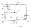
- the main circuit breaker 10 the circuit structure of which is shown in FIG. 4, has an input-side connection terminal 20 and an output-side connection terminal 22, which are connected to one another by a main current path 24.
- a main contact point 26 is arranged in this main current path 24.
- a main switching mechanism 28 is provided for actuating the main contact point 26 and can be acted upon by an electromagnetic quick release device 30 arranged in the main current path 24 behind the main contact point 26 in the energy flow direction.
- the solenoid 31 of the electromagnetic quick release is switched between the main contact point 26 and the outgoing connection terminal 22 in the main current path 24.
- an impact armature not shown here in the trigger coil 31 of the electromagnetic quick release 30, acts directly on the main contact point 26.
- an overcurrent release 32 is arranged in the main current path 24 between the access-side terminal 20 and the main contact point 26, which also cooperates with the main switching mechanism 28.
- a secondary current path 34 which is electrically connected in parallel with the main current path 24 and in the line path of which a coil 35 of a time control device 36 and a further contact point 40 are arranged.
- the further contact point 40 is operatively connected to the main switching mechanism 28 and to a switching lock 37.
- the main contact point 26 has a movable contact piece 27 which engages in a latching device 29 provided according to the invention when opened by the release coil 31 in a position between the closed and the open position.
- the switching lock 37 which belongs to the time control device 36 and is actuated by it.
- the key switch 37 serves u. a. for unlocking the movable contact piece 27.
- a manual control handle 42 is provided which is in operative connection with the main switching mechanism 28 and with the timing control device 36 and the latching device 29.
- the operating current I B flows from the connection terminal 20 on the access side, which is connected to the supply network 16, via the main current path 24 to the connection terminal 22 on the output side, to which the individual consumer networks 13 connect.
- the main contact point 26 is closed.
- a short-circuit current I K occurs , which, as indicated in FIG. 1, can be present both in a consumer 14 and between the main circuit breaker and the common branching point 18 from which the consumer networks 13 are fed
- the trigger coil 31 of the electromagnetic quick release device becomes 30 excited, whereby the main contact point 26 is opened immediately and the movable contact piece 27 engages in the latching device 29 during its opening movement.
- the main current path 24 is thus interrupted.
- the damped short-circuit current which is identified in FIGS. 2 and 3 by I K ', flows through the high-impedance branch current path 34, which is constructed from the electrical series connection of the coil 35, designed as a voltage coil, of the timing control element 36 and the contact point 40.
- the tripping behavior of the coil 35 of the timing control device 36 is characterized by the curve shape s (t) in FIGS. 2 and 3 as follows:
- a short-circuit current I K conducted as a result of a short circuit in the secondary current path 34 begins at t 1 the first half-wave, which is striving for a maximum value.
- the time control device 36 is accordingly activated by energizing the coil 35 and brought to a predetermined energy level with a steep increase, which is reached at t2.
- the timing control device 36 opens the isolating point 40 in the bypass circuit 34 via the switching mechanism 37 and the damped short-circuit current I K is switched off.
- the energy level is for a predetermined time, e.g. B. half a period.
- a discharge process of the timing control device 36 is initiated, which has an exponential course and which is shown in the curve in FIG. 2 as a continuous falling line.
- the separation point 40 is closed again, and the cascade network connected to the main circuit breaker is again live.
- the movable contact piece 27 is released from the main contact point 26, which is then closed.
- FIG. 3 shows the case in which the short-circuit current has not yet been switched off after the first half-wave. Therefore, with the second half-wave, which begins at t3 and similar to the time course of the first half-wave ends at t4, the discharge process of the timing device is stopped because the short-circuit current I K 'activates the timing device 36 from the coil 35 at t3 again and so the trigger level s for the switching mechanism 37 is not reached, the separation point 40 opens again at t4 and the unlocking of the movable contact piece 27 is prevented. Accordingly, the movable contact piece 27 of the main contact point 26 remains trapped in the latching device 29 and the main contact point 26 is opened.
- the instantaneous switch-off must be ensured. This is ensured with the help of the electromagnetic quick release, which works together with the main switching mechanism 28.
- the main switching mechanism is acted upon by the electromagnetic quick release 30, the main contact point 26 and the second contact point 40 in the secondary current path are opened immediately and the main circuit breaker 10 is thus switched off.
- the movable contact piece 27 of the main contact point 26 is held in the latching device 29.
- the hand control handle 42 is actuated, the further contact point 40 in the bypass path 34 is initially closed, while the main contact point 26 remains open, so that there cannot be a current flow through the main contact point 26 at the first moment of switching on, but only a current flow via the bypass path comes about.
- the latching device 29 is also unlocked by the switching lock 37. They are activated in accordance with the time profile of the time control device 36 described above, which is acted upon directly by the manual control handle 42.
- the coil 35 activates the time control device 36, which initially maintains the energy level it has reached according to its characteristic. If the short-circuit current is subsequently switched off by a downstream circuit breaker, the isolating point 40 in the secondary current path is first closed and then the movable contact piece 27 of the main contact point 26 is released by the switching mechanism 37, as previously described.
- the time control element 36 is reactivated by the coil 35 and reaches the original energy level again, so that the main contact point 26 is not closed and instead the main switching mechanism 28 is acted upon. As described above, this leads to the final shutdown of the main circuit breaker.
Landscapes
- Emergency Protection Circuit Devices (AREA)
Applications Claiming Priority (2)
| Application Number | Priority Date | Filing Date | Title |
|---|---|---|---|
| DE3824026 | 1988-07-15 | ||
| DE19883824026 DE3824026A1 (de) | 1988-07-15 | 1988-07-15 | Selektive ueberstromschutzeinrichtung |
Publications (2)
| Publication Number | Publication Date |
|---|---|
| EP0350824A2 true EP0350824A2 (fr) | 1990-01-17 |
| EP0350824A3 EP0350824A3 (fr) | 1991-07-17 |
Family
ID=6358748
Family Applications (1)
| Application Number | Title | Priority Date | Filing Date |
|---|---|---|---|
| EP19890112548 Withdrawn EP0350824A3 (fr) | 1988-07-15 | 1989-07-10 | Dispositif de protection sélective contre la surintensité |
Country Status (2)
| Country | Link |
|---|---|
| EP (1) | EP0350824A3 (fr) |
| DE (1) | DE3824026A1 (fr) |
Cited By (2)
| Publication number | Priority date | Publication date | Assignee | Title |
|---|---|---|---|---|
| FR2762156A1 (fr) * | 1997-04-15 | 1998-10-16 | Schneider Electric Sa | Declencheur electronique selectif, disjoncteur comportant un tel declencheur et procede de declenchement selectif |
| US7378761B2 (en) | 2002-08-02 | 2008-05-27 | Protectelec Pty Ltd | Control circuit and a method for electrically connecting a load to a power source |
Family Cites Families (5)
| Publication number | Priority date | Publication date | Assignee | Title |
|---|---|---|---|---|
| BE443889A (fr) * | 1940-09-25 | |||
| DE2854616C2 (de) * | 1978-12-18 | 1984-03-22 | Brown, Boveri & Cie Ag, 6800 Mannheim | Selektivschutzeinrichtung |
| DE2930960A1 (de) * | 1979-07-31 | 1981-02-19 | Bbc Brown Boveri & Cie | Selektivschutzeinrichtung |
| DE3137727A1 (de) * | 1981-09-22 | 1983-04-07 | Siemens AG, 1000 Berlin und 8000 München | Leitungsschutzschalteranordnung |
| DE3316230C2 (de) * | 1982-05-15 | 1985-04-25 | Hager Electro GmbH + Co, 6601 Ensheim | Schutzschalter gegen Überstrom und Kurzschluß |
-
1988
- 1988-07-15 DE DE19883824026 patent/DE3824026A1/de not_active Ceased
-
1989
- 1989-07-10 EP EP19890112548 patent/EP0350824A3/fr not_active Withdrawn
Cited By (4)
| Publication number | Priority date | Publication date | Assignee | Title |
|---|---|---|---|---|
| FR2762156A1 (fr) * | 1997-04-15 | 1998-10-16 | Schneider Electric Sa | Declencheur electronique selectif, disjoncteur comportant un tel declencheur et procede de declenchement selectif |
| EP0872939A1 (fr) * | 1997-04-15 | 1998-10-21 | Schneider Electric Sa | Déclencheur électronique sélectif, disjoncteur comportant un tel déclencheur et procédé de déclenchement sélectif |
| US6137665A (en) * | 1997-04-15 | 2000-10-24 | Schneider Electric Sa | Selective electronic trip unit, a circuit breaker comprising such a trip unit and a selective tripping process |
| US7378761B2 (en) | 2002-08-02 | 2008-05-27 | Protectelec Pty Ltd | Control circuit and a method for electrically connecting a load to a power source |
Also Published As
| Publication number | Publication date |
|---|---|
| DE3824026A1 (de) | 1990-01-18 |
| EP0350824A3 (fr) | 1991-07-17 |
Similar Documents
| Publication | Publication Date | Title |
|---|---|---|
| DE2649056A1 (de) | Motorschutzschalter | |
| CH653188A5 (de) | Selektive sicherheitsschalteinrichtung zum schutz einer leistungsverteilungsanlage. | |
| DE2854616C2 (de) | Selektivschutzeinrichtung | |
| DE1194959B (de) | Ausloeseanordnung fuer einen elektrischen Leistungsschalter | |
| EP0350829B1 (fr) | Dispositif sélectif de protection contre les courants de court-circuit | |
| DE2854711A1 (de) | Selektivschutzeinrichtung | |
| EP0534250B1 (fr) | Procédé et dispositif pour protéger un circuit courant alternatif | |
| CH623173A5 (fr) | ||
| DE2854637C2 (de) | Als Gruppenschutzschalter dienendes elektrisches Installationsschaltgerät | |
| EP0453776B1 (fr) | Mécanisme de couplage avec disjoncteur ou sectionneur de charge et fusible | |
| DE3316230A1 (de) | Leitungs- und/oder geraeteschutzschalter gegen ueberstrom und kurzschluss | |
| DE3824026A1 (de) | Selektive ueberstromschutzeinrichtung | |
| DE1197967B (de) | Mehrpoliger Netzschutzschalter fuer Nieder-spannungs-Hochstrom-Mehrphasenanlagen | |
| DE749161C (de) | UEberstromschutzanordnung fuer Drehstrommotoren und andere Stromverbraucher mit erhoehtem Anlaufstrom unter Tage | |
| AT408044B (de) | Fehlerstromschutzschalter | |
| DE1149772B (de) | Antriebssystem fuer Synchronschalter | |
| DE617225C (de) | Schutzschaltung gegen die beim Bruch vom Nulleiter auftretenden zu hohen Beruehrungsspannungen der Nulleiter innerhalb von Verteilungsnetzen | |
| DE254796C (fr) | ||
| DE744004C (de) | Schaltanordnung zur selbsttaetigen Steuerung der Schalter elektrischer Verteilungsanlagen | |
| DE69225127T2 (de) | Selektiver automatischer Sicherheitsschalter | |
| AT205573B (fr) | ||
| DE617144C (de) | Schutzschaltung fuer vermaschte Niederspannungsverteilungsnetze | |
| DE673208C (de) | Schutzschaltung fuer vermaschte Niederspannungsverteilungsnetze | |
| DE589378C (de) | Einrichtung zum selektiven Abschalten von Netzteilen | |
| DE593390C (de) | Schutzeinrichtung fuer parallele Drehstromleitungen |
Legal Events
| Date | Code | Title | Description |
|---|---|---|---|
| PUAI | Public reference made under article 153(3) epc to a published international application that has entered the european phase |
Free format text: ORIGINAL CODE: 0009012 |
|
| AK | Designated contracting states |
Kind code of ref document: A2 Designated state(s): AT BE CH DE FR GB IT LI |
|
| RIN1 | Information on inventor provided before grant (corrected) |
Inventor name: RUNTSCH, ERHARD Inventor name: GOEHLE, ROLF Inventor name: DYMKE, DIETMAR Inventor name: GREEFE, KLAUS Inventor name: SCHMITT, HERMANN Inventor name: VELTEN, WALTER |
|
| PUAL | Search report despatched |
Free format text: ORIGINAL CODE: 0009013 |
|
| AK | Designated contracting states |
Kind code of ref document: A3 Designated state(s): AT BE CH DE FR GB IT LI |
|
| 17P | Request for examination filed |
Effective date: 19910805 |
|
| 17Q | First examination report despatched |
Effective date: 19940303 |
|
| STAA | Information on the status of an ep patent application or granted ep patent |
Free format text: STATUS: THE APPLICATION IS DEEMED TO BE WITHDRAWN |
|
| 18D | Application deemed to be withdrawn |
Effective date: 19940702 |