EP0350853A1 - Procédé et appareil pour filtrer des dispersions gazeuses ou liquides - Google Patents
Procédé et appareil pour filtrer des dispersions gazeuses ou liquides Download PDFInfo
- Publication number
- EP0350853A1 EP0350853A1 EP89112642A EP89112642A EP0350853A1 EP 0350853 A1 EP0350853 A1 EP 0350853A1 EP 89112642 A EP89112642 A EP 89112642A EP 89112642 A EP89112642 A EP 89112642A EP 0350853 A1 EP0350853 A1 EP 0350853A1
- Authority
- EP
- European Patent Office
- Prior art keywords
- dispersion
- hollow
- flow channel
- threads
- porous
- Prior art date
- Legal status (The legal status is an assumption and is not a legal conclusion. Google has not performed a legal analysis and makes no representation as to the accuracy of the status listed.)
- Granted
Links
Images


Classifications
-
- B—PERFORMING OPERATIONS; TRANSPORTING
- B01—PHYSICAL OR CHEMICAL PROCESSES OR APPARATUS IN GENERAL
- B01D—SEPARATION
- B01D63/00—Apparatus in general for separation processes using semi-permeable membranes
- B01D63/02—Hollow fibre modules
- B01D63/026—Wafer type modules or flat-surface type modules
-
- B—PERFORMING OPERATIONS; TRANSPORTING
- B01—PHYSICAL OR CHEMICAL PROCESSES OR APPARATUS IN GENERAL
- B01D—SEPARATION
- B01D46/00—Filters or filtering processes specially modified for separating dispersed particles from gases or vapours
- B01D46/24—Particle separators, e.g. dust precipitators, using rigid hollow filter bodies
-
- B—PERFORMING OPERATIONS; TRANSPORTING
- B01—PHYSICAL OR CHEMICAL PROCESSES OR APPARATUS IN GENERAL
- B01D—SEPARATION
- B01D46/00—Filters or filtering processes specially modified for separating dispersed particles from gases or vapours
- B01D46/54—Particle separators, e.g. dust precipitators, using ultra-fine filter sheets or diaphragms
-
- B—PERFORMING OPERATIONS; TRANSPORTING
- B01—PHYSICAL OR CHEMICAL PROCESSES OR APPARATUS IN GENERAL
- B01D—SEPARATION
- B01D63/00—Apparatus in general for separation processes using semi-permeable membranes
- B01D63/02—Hollow fibre modules
- B01D63/04—Hollow fibre modules comprising multiple hollow fibre assemblies
- B01D63/043—Hollow fibre modules comprising multiple hollow fibre assemblies with separate tube sheets
-
- B—PERFORMING OPERATIONS; TRANSPORTING
- B01—PHYSICAL OR CHEMICAL PROCESSES OR APPARATUS IN GENERAL
- B01D—SEPARATION
- B01D2315/00—Details relating to the membrane module operation
- B01D2315/06—Submerged-type; Immersion type
Definitions
- the invention relates to a method and a device for filtering gaseous or liquid dispersions through the porous wall of hollow fibers by adjusting and maintaining a pressure difference between the dispersion side and the filtrate side (permeate side), in which the permeable components of the dispersion only through the pores of the wall of the hollow fibers stream.
- the invention thus relates to a so-called dead-end filtering method, also called a static filtering method, and a device suitable for this.
- This filtering process is characterized in that all permeable constituents of a dispersion to be filtered only pass through the filter medium, in the present case through the pores of the wall of hollow filaments, and the constituents of the dispersion retained by the filter medium, i.e. from the porous wall of the hollow filaments accumulate in front of the filter medium or deposit on it and form a so-called filter cake. This results in a gradual deterioration in the filter performance, which ultimately makes it necessary to clean the filter medium, for example by backwashing, or to replace the filter medium.
- hollow fibers with a porous wall have been used, which have a very high proportion of pores in relation to the hollow fiber wall surface.
- the hollow threads are arranged essentially parallel to the longitudinal axis of the flow channel for the dispersion to be filtered.
- a disadvantage of the known filtering methods and the devices used for this purpose is that in these the hollow fibers are essentially flowed through by the dispersion in their longitudinal direction.
- the length of the hollow threads essentially corresponds to the length of the filter unit, that is to say, for example, the so-called hollow thread filter candle.
- the length of such filter cartridges is often determined by the dimensions of already existing filter devices, because efforts are often made to leave an existing filter device essentially unchanged and merely to replace conventional filter cartridges with hollow fiber filter cartridges.
- the length of the porous hollow filaments had to be dimensioned relatively large in the case of the hollow filament filter candles known to date, which led to a relatively high flow resistance in the lumen of the hollow filaments, i.e. to a high pressure loss, and consequently to a considerable reduction in the filter performance.
- the present invention is therefore based on the object of providing a method and a device with which at least the disadvantages described above are eliminated and in particular an increase in their filter performance which is directly proportional to an extension of the hollow fiber filter candle is achieved.
- the dispersion to be filtered flows essentially parallel to the longitudinal axis of the device (filter candle) and the porous hollow fibers are transverse to this direction of flow - that is to say not parallel, and also not essentially parallel, to the longitudinal axis of the device - Arranged so that they are essentially transverse to the dispersion be flown to.
- the hollow filaments are preferably linear.
- the greatest length of the hollow filaments essentially corresponds to the (largest) diameter of the filter candle and thus the longest flow path for the permeated constituents of the dispersion in the hollow filaments corresponds essentially to only half (largest) diameter of the filter candle.
- the longest flow path for the permeated constituents of the dispersion is thus considerably shorter than the longest flow path of the dispersion when flowing around the hollow filaments before filtration, i.e. the Length of the flow channel filled with the porous hollow threads for the dispersion to be filtered.
- the porous hollow threads are arranged substantially perpendicular to the longitudinal axis of the flow channel for the dispersion to be filtered, so that the dispersion flows and flows around the porous hollow threads essentially perpendicular to their longitudinal axis.
- the filtrate (permeate) preferably emerges on the outer circumferential surface of the filter candle from the porous hollow threads into a filtrate collecting space or channel.
- the hollow fiber arrangement of the device according to the invention can be achieved by using a conventional hollow fiber sheet, for example a hollow thread mat, a hollow fiber fabric, a hollow fiber layer u.
- a conventional hollow fiber sheet for example a hollow thread mat, a hollow fiber fabric, a hollow fiber layer u.
- Individual filter elements are punched out and stacked on top of one another and this hollow fiber package thus obtained is now subjected to an embedding process in which the ends of the hollow fibers are embedded.
- the hollow fiber ends can then be exposed by removing part of the embedding, ie opened again.
- the porous hollow fibers can advantageously be arranged in parallel within a layer of the hollow fiber package. However, an irregular arrangement of the hollow threads is also possible.
- the hollow filaments of adjacent layers can also preferably cross.
- the filter elements can also be punched out with simultaneous welding of the interfaces.
- the cross section of the hollow fiber package can be any, in particular round, square or hexagonal.
- the porous hollow filaments can also have any cross section, for example a round, oval, lobal and the like cross section.
- porous hollow threads are suitable which cause a dispersion to be filtered when a driving force, for example a pressure gradient, is applied, the selection of the most suitable hollow threads being able to be carried out on the basis of simple preliminary tests.
- a driving force for example a pressure gradient
- All known organic and inorganic materials from which porous hollow threads can be produced are suitable for producing suitable porous hollow threads. The selection of the most suitable material for the hollow fibers depends on the chemical and physical properties of the dispersion to be filtered.
- Hollow threads are understood to mean tubular or tubular structures with any dimensions and wall thicknesses, that is to say, for example, so-called capillary membranes, hollow fibers, tubular membranes, tubes, pipes, tubes, etc. These can be flexible or more or less rigid.
- the inside thread diameter is generally 150 to 5500 ⁇ m.
- the wall thickness of the hollow filaments should be as small as possible without the hollow filaments collapsing at the required pressure difference.
- a wall thickness in the range from 50 to 1500 ⁇ m generally meets these requirements.
- the (nominal) diameter of the pores of the porous wall of the hollow fibers depends on the respective area of application and the specific requirements therefor and is usually in the range from 0.05 to 10 ⁇ m.
- the maximum length of the porous hollow filaments should be dimensioned taking into account their inner diameter, the ratio of hollow filament length to hollow filament inner diameter being advantageous up to a value of 1000. However, the maximum length of the porous hollow fibers should be at most half the length of the hollow fiber package.
- the method and the device according to the invention are suitable for filtering solid particles from a gas (mixture) or a liquid or a liquid mixture, including the sterile filtration of liquids and gases in the pharmaceutical, biotechnological and chemical industry, and the purest water production in the Electronics industry, sterilization filtration in the beverage industry (beer, wine, Juices), the filtering of fuels (eg for aircraft), the filtering of fluids to be analyzed in front of the analyzers, the exhaust gas and exhaust air purification and the like. the like
- inventive method and the inventive device are also suitable for separating liquid droplets from gases and liquids, e.g. for filtering oil droplets from compressor air, water droplets from fuels and the like. the like
- the hollow fiber package can be designed according to the invention in such a way that the packing density of the porous hollow fibers increases in the direction of flow for the dispersion to be filtered and / or the pore size (pore diameter) of the hollow fibers increases and / or the pore volume, that is to say the number of pores per unit area, increases and / or the hollow thread diameter decreases, in order to obtain more filter area per unit volume even with the packing density remaining the same, and / or the length of the porous hollow fibers increases.
- all of these configuration options can be selected individually or in any combination.
- the length of the hollow fiber filter cartridge can be extended without increasing the pressure loss in the hollow fibers and without appreciable increase in the total pressure loss of the filter cartridge.
- the extension of the hollow fiber filter candle leads to an increase in the filtering capacity which is directly proportional to the extension.
- a hollow fiber package with a high packing density can be achieved with a uniform flow.
- the filter performance can be measured differently in the direction of flow of the dispersion to be filtered, for example increasing or decreasing.
- the pressure loss in the porous hollow filaments is significantly lower than in conventional hollow filament filter cartridges with hollow filaments arranged parallel to the longitudinal axis of the filter candle.
- the thickness (wall thickness) of the tube formed from the investment material and enclosing the flow channel for the dispersion to be filtered is to be dimensioned such that it withstands the pressures used in operational use.
- a hollow fiber filter candle according to the invention can be obtained by stacking a corresponding number of hollow fiber layers on top of one another and then embedding the hollow fiber ends in a manner known per se.
- the individual sections can be connected to one another by gluing, welding, pressing together with interposed seals or in some other way.
- reinforcing agents such as support disks, support rings, perforated disks, textile or metallic fabrics and the like can be between individual hollow fiber layers and / or the individual sections. Like. Be arranged. These can also be arranged and embedded so that they reinforce the investment, e.g. a potting compound, formed wall of the flow channel for the dispersion to be filtered. In this way it is in fact possible under certain circumstances to reduce the wall thickness and in this way save embedding material and gain filter surface.
- Figure 1a shows a section 1 of the device according to the invention, in which the porous hollow threads 2 of a layer are arranged parallel to one another and the hollow threads 2 of adjacent layers intersect and, if necessary, touch at the crossing points.
- the hollow threads 2 open with their open ends on the circumferential surface of the embedding material 3 that surrounds the flow channel for the dispersion to be filtered.
- the flow channel is delimited by the embedding material 3, in which the ends of the porous hollow threads 2 are embedded.
- the feed for the dispersion to be filtered is located on the end faces of section 1 of the device, as indicated by the two arrows drawn vertically.
- the permeate (filtrate) first emerges through the pores of the hollow fibers 2 into the lumen of the hollow fibers 2 and then out of the open ends of the hollow fibers 2, as indicated by a few arrows.
- This embodiment shows very clearly that the length of section 1 of the device, ie the flow channel filled with hollow fibers 2 for the dispersion to be filtered, can be extended as desired without the length of the hollow fibers 2 increasing.
- a device according to the invention can be produced by stacking a plurality of the section 1 shown in FIG. 1a or by dimensioning the length of the flow channel filled with hollow fibers 2 for the dispersion to be filtered at least twice as long as the maximum length of the porous hollow fibers 2. The maximum length of the porous hollow fibers 2 is then at most half the length of the flow channel filled with porous hollow fibers 2 for the dispersion to be filtered, that is to say of the hollow fiber package.
- Figure 1b shows a device 1 according to the invention of any length in plan view.
- the porous hollow threads 2 are arranged one above the other in layers, the hollow threads 2 of a layer being arranged parallel to one another and at the same mutual distance from one another.
- the hollow threads 2 of adjacent layers intersect at an angle of 60 o or 120 o .
- the flow channel for the dispersion to be filtered is also circular, while the outer contour of the device (filter candle) 1 has a hexagonal cross section.
- the open ends of the porous hollow threads 2 also open here on the outer surface of the tubular, externally hexagonal investment material 3 for the porous hollow threads 2.
- This figure shows very clearly that with the present invention, a very uniform distribution and a very orderly arrangement of the hollow threads 2 can be achieved.
- the packing density can be increased in a simple manner, for example by reducing the mutual distance between the porous hollow fibers 2 and vice versa.
- FIG 2 the operation of the device according to the invention is shown in a simplified schematic representation.
- a filter candle 6 according to the invention is arranged in a container 4 filled with permeate (filtrate) 5.
- the device (filter candle) is closed on one end face, while the opposite end face is connected to a hose line 7, which forms the feed for a dispersion 8 to be filtered.
- the porous hollow threads 2 are also arranged essentially perpendicular to the longitudinal axis of the flow channel for the dispersion to be filtered and are flowed and flowed around by the dispersion essentially transversely, ie perpendicular to its longitudinal axis.
- the permeable Components of the dispersion (permeate; filtrate), which pass through the pores of the wall of the hollow fibers 2 into the lumen of the hollow fibers 2, leave the hollow fibers 2 in the manner and direction shown by the arrows 9.
- This embodiment clearly shows that, according to the invention, the longest flow path of the permeated constituents of the dispersion in the lumen of the hollow filaments 2 is considerably shorter than the longest flow path of the dispersion when flowing around the hollow filaments 2 before the filtration.
- the greatest length of the porous hollow fibers 2 is considerably smaller than the length of the flow channel filled with hollow fibers 2 for the dispersion to be filtered.
- a plurality of filter candles 6 can also be arranged in the container 4 and connected to a common or individual feed line 7.
- the device 1 is arranged in a closed housing 12 which has only one inlet opening for the dispersion 8 to be filtered and one outlet opening for the filtrate 9.
- the tubular investment 11 for the porous hollow filaments 2 is surrounded by a support grid 13.
- the filtrate emerging from the porous hollow threads 2 first passes through the support grid 13 into the collecting space 15, which surrounds the filter candle in the form of an annular channel.
- the remaining structure of the device 1 corresponds to that of the filter candle 6 shown in FIG. 2 and described above.
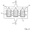
- a total of three filter candles 6 according to the invention are on one Common partition 10 is arranged, which separates the distribution space 16 for the dispersion 8 to be filtered from the collection space 15 for the filtrate 9 to be removed. Otherwise, the spaces 15 and 16 mentioned are delimited by the housing 14. The mode of operation of this device is evident from the description of FIGS. 2 and 3 and the statements made above.
- Figures 2 to 4 thus make it clear that the device according to the invention individually or in several copies in an open container (Figure 2), individually in a closed housing adapted to the size of the device (filter candle) ( Figure 3) or in several copies in one common closed housing ( Figure 4) can be arranged.
- An adaptation of the filter candle according to the invention to existing devices is thus possible without the length of the filter candle representing a performance-limiting variable.
Landscapes
- Chemical & Material Sciences (AREA)
- Chemical Kinetics & Catalysis (AREA)
- Separation Using Semi-Permeable Membranes (AREA)
- Filtering Materials (AREA)
Applications Claiming Priority (2)
| Application Number | Priority Date | Filing Date | Title |
|---|---|---|---|
| DE3823858 | 1988-07-14 | ||
| DE3823858A DE3823858A1 (de) | 1988-07-14 | 1988-07-14 | Verfahren und vorrichtung zum filtrieren von gasfoermigen oder fluessigen dispersionen |
Publications (2)
| Publication Number | Publication Date |
|---|---|
| EP0350853A1 true EP0350853A1 (fr) | 1990-01-17 |
| EP0350853B1 EP0350853B1 (fr) | 1993-06-16 |
Family
ID=6358647
Family Applications (1)
| Application Number | Title | Priority Date | Filing Date |
|---|---|---|---|
| EP89112642A Expired - Lifetime EP0350853B1 (fr) | 1988-07-14 | 1989-07-11 | Procédé et appareil pour filtrer des dispersions gazeuses ou liquides |
Country Status (5)
| Country | Link |
|---|---|
| EP (1) | EP0350853B1 (fr) |
| JP (1) | JPH0263528A (fr) |
| AU (1) | AU620627B2 (fr) |
| DE (2) | DE3823858A1 (fr) |
| DK (1) | DK347689A (fr) |
Cited By (6)
| Publication number | Priority date | Publication date | Assignee | Title |
|---|---|---|---|---|
| EP0443206A3 (en) * | 1990-02-17 | 1991-10-02 | Akzo N.V. | Process for preparing hollow filament stacks |
| EP0454918A1 (fr) * | 1989-03-24 | 1991-11-06 | The Standard Oil Company | Module de séparation à fibres creuses et méthode pour son utilisation |
| US5164081A (en) * | 1989-03-24 | 1992-11-17 | The Standard Oil Company | Apparatus for separation and for treatment of fluid feedstreams, wafers for use therein and related methods |
| US5174900A (en) * | 1989-03-24 | 1992-12-29 | The Standard Oil Company | Apparatus for separation and for treatment of fluid feedstreams, wafers for use therein and related methods |
| WO2006081059A2 (fr) | 2005-01-26 | 2006-08-03 | Celgard Llc | Module à fibres creuses |
| CN101933784A (zh) * | 2009-06-30 | 2011-01-05 | 杨刚 | 水过滤式手提吸尘器 |
Families Citing this family (3)
| Publication number | Priority date | Publication date | Assignee | Title |
|---|---|---|---|---|
| JPH0745008B2 (ja) * | 1990-05-25 | 1995-05-17 | ザ スタンダード オイル カンパニー | 流体分離装置とその方法 |
| DE19913416A1 (de) * | 1999-03-25 | 2000-10-05 | Jostra Medizintechnik Ag | Vorrichtung mit mindestens einer in Form einer Hohlfaser vorliegenden Membran zum Filtrieren von Flüssigkeiten |
| JP2007159444A (ja) * | 2005-12-12 | 2007-06-28 | Nippon Chemicals Hanbai Kk | 果汁製造方法、及びバナナ濃縮果汁 |
Citations (2)
| Publication number | Priority date | Publication date | Assignee | Title |
|---|---|---|---|---|
| DE1642811B2 (de) * | 1964-12-09 | 1977-07-14 | Cordis Dow Corp, Miami, Fla. (V-StA.) | Diffusionszelle |
| GB2135902A (en) * | 1983-02-28 | 1984-09-12 | Kuraray Co | Membrane fibre filtration apparatus |
Family Cites Families (6)
| Publication number | Priority date | Publication date | Assignee | Title |
|---|---|---|---|---|
| US3198335A (en) * | 1965-08-03 | Permeation apparatus | ||
| DE890299C (de) * | 1951-12-18 | 1953-09-17 | Draegerwerk Ag | Gasfilteranlage |
| FR2222134A1 (en) * | 1973-03-19 | 1974-10-18 | Rhone Poulenc Sa | Appts for permeation through hollow fibres - allows simple construction and efficient separation and mixing processes |
| FR2236537B1 (fr) * | 1973-07-11 | 1977-12-23 | Rhone Poulenc Ind | |
| DE2935622C2 (de) * | 1979-09-04 | 1985-04-11 | Friedrich 6000 Frankfurt Wolff | Vorrichtung zur Erhöhung oder Verminderung des Sauerstoffanteils der Luft sowie Verwendung dieser Vorrichtung |
| DE3733542A1 (de) * | 1986-10-13 | 1988-07-14 | Akzo Gmbh | Vorrichtung zum stoffaustausch |
-
1988
- 1988-07-14 DE DE3823858A patent/DE3823858A1/de not_active Withdrawn
-
1989
- 1989-07-11 DE DE8989112642T patent/DE58904695D1/de not_active Expired - Fee Related
- 1989-07-11 EP EP89112642A patent/EP0350853B1/fr not_active Expired - Lifetime
- 1989-07-13 DK DK347689A patent/DK347689A/da not_active Application Discontinuation
- 1989-07-14 AU AU38156/89A patent/AU620627B2/en not_active Ceased
- 1989-07-14 JP JP1180669A patent/JPH0263528A/ja active Pending
Patent Citations (2)
| Publication number | Priority date | Publication date | Assignee | Title |
|---|---|---|---|---|
| DE1642811B2 (de) * | 1964-12-09 | 1977-07-14 | Cordis Dow Corp, Miami, Fla. (V-StA.) | Diffusionszelle |
| GB2135902A (en) * | 1983-02-28 | 1984-09-12 | Kuraray Co | Membrane fibre filtration apparatus |
Cited By (10)
| Publication number | Priority date | Publication date | Assignee | Title |
|---|---|---|---|---|
| EP0454918A1 (fr) * | 1989-03-24 | 1991-11-06 | The Standard Oil Company | Module de séparation à fibres creuses et méthode pour son utilisation |
| US5164081A (en) * | 1989-03-24 | 1992-11-17 | The Standard Oil Company | Apparatus for separation and for treatment of fluid feedstreams, wafers for use therein and related methods |
| US5174900A (en) * | 1989-03-24 | 1992-12-29 | The Standard Oil Company | Apparatus for separation and for treatment of fluid feedstreams, wafers for use therein and related methods |
| EP0443206A3 (en) * | 1990-02-17 | 1991-10-02 | Akzo N.V. | Process for preparing hollow filament stacks |
| US5126053A (en) * | 1990-02-17 | 1992-06-30 | Akzo N.V. | Method for manufacturing hollow fiber piles |
| AU629457B2 (en) * | 1990-02-17 | 1992-10-01 | Akzo N.V. | A method for manufacturing hollow fibre piles |
| WO2006081059A2 (fr) | 2005-01-26 | 2006-08-03 | Celgard Llc | Module à fibres creuses |
| US7628916B2 (en) | 2005-01-26 | 2009-12-08 | Celgard Llc | Hollow fiber module |
| CN101933784A (zh) * | 2009-06-30 | 2011-01-05 | 杨刚 | 水过滤式手提吸尘器 |
| CN101933784B (zh) * | 2009-06-30 | 2015-03-25 | 杨刚 | 水过滤式手提吸尘器 |
Also Published As
| Publication number | Publication date |
|---|---|
| AU620627B2 (en) | 1992-02-20 |
| EP0350853B1 (fr) | 1993-06-16 |
| DE3823858A1 (de) | 1990-02-22 |
| DE58904695D1 (de) | 1993-07-22 |
| AU3815689A (en) | 1990-01-18 |
| JPH0263528A (ja) | 1990-03-02 |
| DK347689D0 (da) | 1989-07-13 |
| DK347689A (da) | 1990-01-15 |
Similar Documents
| Publication | Publication Date | Title |
|---|---|---|
| DE69906109T2 (de) | Filter und verfahren zum filtrieren eines fluids | |
| EP0371189B1 (fr) | Module à fibres creuses, procédé de fabrication dudit module et appareil pour la mise en oeuvre dudit procédé de fabrication | |
| DE68916233T2 (de) | Querstromfilteranordnung und verfahren zur herstellung. | |
| EP0609275B1 (fr) | Element ceramique de filtrage a courant tangentiel de liquides et de gaz | |
| DE3851167T2 (de) | Spiralförmig gewickelte, konische Filterpatrone und Verfahren zu ihrer Herstellung. | |
| DE4319261C2 (de) | Schraubenförmig umwickeltes Filterelement | |
| DE68909463T2 (de) | Spiralig gewickeltes Filterelement. | |
| DE2457289C3 (de) | Trennanordnung für ein öl-Wasser-Gemisch | |
| DE3500368C2 (fr) | ||
| DE69130393T2 (de) | Modulare, mikroporöse filteranlagen | |
| DE2441333C3 (de) | Verfahren zur Herstellung einer Anordnung aus Hohlfasern | |
| DE2614336A1 (de) | Rohrfoermiges filterelement und verfahren zu seiner herstellung | |
| CH638689A5 (de) | Verfahren zur herstellung eines filterelements, nach dem verfahren hergestelltes filterelement und vorrichtung zur durchfuehrung des verfahrens. | |
| EP3436183B1 (fr) | Dispositif d'échange de substance et procédé de fabrication | |
| EP0350853B1 (fr) | Procédé et appareil pour filtrer des dispersions gazeuses ou liquides | |
| DE69515773T2 (de) | Monolitischer, poröser Träger für Filtrationsmembrane | |
| WO1990009229A1 (fr) | Filtre a spirale | |
| DE4308850A1 (de) | Hohlfadenmatte | |
| DE3805361A1 (de) | Integralfilter fuer fluide aus mehreren ineinander geschachtelten filterelementen mit unterschiedlichem rueckhaltevermoegen und gehaeuse dafuer | |
| DE3519620A1 (de) | Einrichtung und verfahren zur steuerung der diffusion von fluidkomponenten | |
| DE2814326A1 (de) | Poroese abstuetzung zur verwendung in einer trenneinrichtung mit hohlfasern | |
| DE2950426A1 (de) | Vorrichtung zum trennen von stroemungsmitteln | |
| DE2529977B2 (de) | Vorrichtung mit Membranen auf rohrförmigen Abstützungen zum Behandeln von Fluiden | |
| DE3733542A1 (de) | Vorrichtung zum stoffaustausch | |
| DE3805299C2 (fr) |
Legal Events
| Date | Code | Title | Description |
|---|---|---|---|
| PUAI | Public reference made under article 153(3) epc to a published international application that has entered the european phase |
Free format text: ORIGINAL CODE: 0009012 |
|
| AK | Designated contracting states |
Kind code of ref document: A1 Designated state(s): AT BE CH DE ES FR GB GR IT LI LU NL SE |
|
| 17P | Request for examination filed |
Effective date: 19900709 |
|
| 17Q | First examination report despatched |
Effective date: 19920206 |
|
| ITF | It: translation for a ep patent filed | ||
| RBV | Designated contracting states (corrected) |
Designated state(s): DE FR IT NL |
|
| GRAA | (expected) grant |
Free format text: ORIGINAL CODE: 0009210 |
|
| AK | Designated contracting states |
Kind code of ref document: B1 Designated state(s): DE FR IT NL |
|
| REF | Corresponds to: |
Ref document number: 58904695 Country of ref document: DE Date of ref document: 19930722 |
|
| ET | Fr: translation filed | ||
| PLBE | No opposition filed within time limit |
Free format text: ORIGINAL CODE: 0009261 |
|
| STAA | Information on the status of an ep patent application or granted ep patent |
Free format text: STATUS: NO OPPOSITION FILED WITHIN TIME LIMIT |
|
| RAP2 | Party data changed (patent owner data changed or rights of a patent transferred) |
Owner name: AKZO NOBEL N.V. |
|
| PGFP | Annual fee paid to national office [announced via postgrant information from national office to epo] |
Ref country code: FR Payment date: 19940601 Year of fee payment: 6 |
|
| 26N | No opposition filed | ||
| PGFP | Annual fee paid to national office [announced via postgrant information from national office to epo] |
Ref country code: DE Payment date: 19940610 Year of fee payment: 6 |
|
| PGFP | Annual fee paid to national office [announced via postgrant information from national office to epo] |
Ref country code: NL Payment date: 19940731 Year of fee payment: 6 |
|
| PG25 | Lapsed in a contracting state [announced via postgrant information from national office to epo] |
Ref country code: NL Effective date: 19960201 |
|
| NLV4 | Nl: lapsed or anulled due to non-payment of the annual fee |
Effective date: 19960201 |
|
| PG25 | Lapsed in a contracting state [announced via postgrant information from national office to epo] |
Ref country code: DE Effective date: 19960402 |
|
| PG25 | Lapsed in a contracting state [announced via postgrant information from national office to epo] |
Ref country code: FR Effective date: 19960430 |
|
| REG | Reference to a national code |
Ref country code: FR Ref legal event code: ST |
|
| REG | Reference to a national code |
Ref country code: FR Ref legal event code: ST |
|
| REG | Reference to a national code |
Ref country code: FR Ref legal event code: ST |
|
| PG25 | Lapsed in a contracting state [announced via postgrant information from national office to epo] |
Ref country code: IT Free format text: LAPSE BECAUSE OF NON-PAYMENT OF DUE FEES;WARNING: LAPSES OF ITALIAN PATENTS WITH EFFECTIVE DATE BEFORE 2007 MAY HAVE OCCURRED AT ANY TIME BEFORE 2007. THE CORRECT EFFECTIVE DATE MAY BE DIFFERENT FROM THE ONE RECORDED. Effective date: 20050711 |