EP0350968A1 - Magasin d'outils pour machines-outils - Google Patents
Magasin d'outils pour machines-outils Download PDFInfo
- Publication number
- EP0350968A1 EP0350968A1 EP89115053A EP89115053A EP0350968A1 EP 0350968 A1 EP0350968 A1 EP 0350968A1 EP 89115053 A EP89115053 A EP 89115053A EP 89115053 A EP89115053 A EP 89115053A EP 0350968 A1 EP0350968 A1 EP 0350968A1
- Authority
- EP
- European Patent Office
- Prior art keywords
- tool
- holes
- storing device
- tools
- base plate
- Prior art date
- Legal status (The legal status is an assumption and is not a legal conclusion. Google has not performed a legal analysis and makes no representation as to the accuracy of the status listed.)
- Ceased
Links
- 239000011248 coating agent Substances 0.000 claims abstract description 14
- 238000000576 coating method Methods 0.000 claims abstract description 14
- 239000000463 material Substances 0.000 claims abstract description 8
- 239000004033 plastic Substances 0.000 claims abstract description 5
- 238000005299 abrasion Methods 0.000 claims description 3
- 230000007723 transport mechanism Effects 0.000 abstract 1
- 230000037431 insertion Effects 0.000 description 2
- 238000003780 insertion Methods 0.000 description 2
- 238000010276 construction Methods 0.000 description 1
- 238000004519 manufacturing process Methods 0.000 description 1
- 239000011159 matrix material Substances 0.000 description 1
- 230000002035 prolonged effect Effects 0.000 description 1
Images
Classifications
-
- B—PERFORMING OPERATIONS; TRANSPORTING
- B23—MACHINE TOOLS; METAL-WORKING NOT OTHERWISE PROVIDED FOR
- B23Q—DETAILS, COMPONENTS, OR ACCESSORIES FOR MACHINE TOOLS, e.g. ARRANGEMENTS FOR COPYING OR CONTROLLING; MACHINE TOOLS IN GENERAL CHARACTERISED BY THE CONSTRUCTION OF PARTICULAR DETAILS OR COMPONENTS; COMBINATIONS OR ASSOCIATIONS OF METAL-WORKING MACHINES, NOT DIRECTED TO A PARTICULAR RESULT
- B23Q3/00—Devices holding, supporting, or positioning work or tools, of a kind normally removable from the machine
- B23Q3/155—Arrangements for automatic insertion or removal of tools, e.g. combined with manual handling
- B23Q3/1552—Arrangements for automatic insertion or removal of tools, e.g. combined with manual handling parts of devices for automatically inserting or removing tools
- B23Q3/15526—Storage devices; Drive mechanisms therefor
-
- B—PERFORMING OPERATIONS; TRANSPORTING
- B23—MACHINE TOOLS; METAL-WORKING NOT OTHERWISE PROVIDED FOR
- B23Q—DETAILS, COMPONENTS, OR ACCESSORIES FOR MACHINE TOOLS, e.g. ARRANGEMENTS FOR COPYING OR CONTROLLING; MACHINE TOOLS IN GENERAL CHARACTERISED BY THE CONSTRUCTION OF PARTICULAR DETAILS OR COMPONENTS; COMBINATIONS OR ASSOCIATIONS OF METAL-WORKING MACHINES, NOT DIRECTED TO A PARTICULAR RESULT
- B23Q3/00—Devices holding, supporting, or positioning work or tools, of a kind normally removable from the machine
- B23Q3/155—Arrangements for automatic insertion or removal of tools, e.g. combined with manual handling
- B23Q3/157—Arrangements for automatic insertion or removal of tools, e.g. combined with manual handling of rotary tools
- B23Q3/15713—Arrangements for automatic insertion or removal of tools, e.g. combined with manual handling of rotary tools a transfer device taking a single tool from a storage device and inserting it in a spindle
-
- E—FIXED CONSTRUCTIONS
- E05—LOCKS; KEYS; WINDOW OR DOOR FITTINGS; SAFES
- E05F—DEVICES FOR MOVING WINGS INTO OPEN OR CLOSED POSITION; CHECKS FOR WINGS; WING FITTINGS NOT OTHERWISE PROVIDED FOR, CONCERNED WITH THE FUNCTIONING OF THE WING
- E05F15/00—Power-operated mechanisms for wings
- E05F15/40—Safety devices, e.g. detection of obstructions or end positions
-
- E—FIXED CONSTRUCTIONS
- E05—LOCKS; KEYS; WINDOW OR DOOR FITTINGS; SAFES
- E05Y—INDEXING SCHEME ASSOCIATED WITH SUBCLASSES E05D AND E05F, RELATING TO CONSTRUCTION ELEMENTS, ELECTRIC CONTROL, POWER SUPPLY, POWER SIGNAL OR TRANSMISSION, USER INTERFACES, MOUNTING OR COUPLING, DETAILS, ACCESSORIES, AUXILIARY OPERATIONS NOT OTHERWISE PROVIDED FOR, APPLICATION THEREOF
- E05Y2999/00—Subject-matter not otherwise provided for in this subclass
Definitions
- the invention relates to a storage plate for machine tools, preferably equipped with an automatic tool changing device, in which each of a plurality of tools is pulled down from the storage plate by means of a tool transport device having a gripper-like tool transport device and containing a tool magazine containing at least one essentially horizontally arranged, corresponding tool receiving holes and handed over to a work unit and, after use, pulled down from the work unit, brought back to the storage disk and inserted from below into one of the tool receiving holes, the tool receiving holes being arranged with means for frictionally holding the tools in the substantially vertical position.
- a storage plate of the aforementioned type which consists of two perforated plates shaped elements, one of which is thinner than the other.
- the two plate-shaped elements are fastened to one another and have holes arranged in a matrix.
- One plate also has wavy grooves, the depth of which is less than the material thickness of this plate.
- Spring wires lie in the grooves in such a way that they engage in the holes and exert a friction on the section of the tools protruding into the holes, which prevent the tools which are inserted from below from falling out.
- This solution has the disadvantage of being relatively expensive to produce.
- the spring wires can also not always ensure a reliable fit of the tools.
- the object of the invention is to provide a storage disk of the generic type of simpler construction and more reliable and permanent functionality.
- a base plate on the top with a coating of resilient, preferably abrasion-resistant material, e.g. Plastic or rubber is provided, which has openings associated with the tool receiving holes and slightly narrower than at least part of their length.
- Such a storage disk is very easy to manufacture and reliable and durable in its function. Only a single base plate is required, the coating of which holds the respective holding shank of the tools used in a frictional manner.
- the holding shank of the respective tool with little play receiving tool holes are at a be special configuration of the inventive concept on its underside, preferably conical, expanded. In this way, the tools can easily be inserted from below into the corresponding tool receiving holes with automatic centering, even if the gripper of the tool transport device is not exactly below the corresponding tool receiving hole.
- the openings on the side of the coating facing the upper side of the base plate have approximately the same diameter as or only a slightly larger diameter than the adjoining tool-holding holes and are directed away from the base plate, preferably conically, except for taper a diameter that is smaller than the smallest diameter of the tool receiving holes. This prevents the coating from being lifted off the base plate from below when the tools are inserted into the tool receiving holes.
- the preferably conical tapering of the diameter of the openings ensures an easy insertion of the tool holding shaft with a secure, friction-locked mounting.
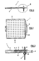
- the storage plate 1 having a grip strip 9 consists essentially of a base plate 6, which is essentially square in FIG. 1, with a coating 5 made of elastic, resilient, preferably abrasion-resistant plastic or rubber material.
- the base plate 6 is equipped with a rectangular grid of holes 3 for receiving tools 2, in the case shown drills. 3, the tools 2 are inserted from below with their holding shank 8 pointing upwards into the corresponding tool receiving hole 3 until a stop 10 comes to rest on the underside of the base plate 6. The insertion is facilitated in that the tool receiving holes 3 are flared downwards.
- the coating 5 applied and fixed on the upper side 4 of the base plate 6, for example glued on, has openings 7 assigned to the tool receiving holes 3.
- the openings 7 adjacent to the base plate have the same diameter as the tool receiving holes 3 at this point, or they are slightly larger in diameter .
- the openings 7 also taper slightly upwards, so that the diameter of the through Refractions 7 above is in any case smaller than the smallest diameter of the tool receiving holes 3.
- the taper is made such that the frictional forces exerted by the coating 5 made of plastic or rubber material on the surface of the holding shank 8 are sufficient to hold the tool 2 despite its weight to hold the corresponding tool holder hole 3.
- the tool 2 can be seen from its storage position shown in FIG. 3 with a gripper down again from the storage plate 1.
- the openings 7 which had previously been widened in accordance with the cross section of the holding shaft 8 and which are exciting around the holding shaft 8 assume the shape which originally tapered upwards. If the material of the coating 5 becomes tired after prolonged use, it can easily be exchanged for a new coating.
Landscapes
- Engineering & Computer Science (AREA)
- Mechanical Engineering (AREA)
- Workshop Equipment, Work Benches, Supports, Or Storage Means (AREA)
- Automatic Tool Replacement In Machine Tools (AREA)
Applications Claiming Priority (3)
| Application Number | Priority Date | Filing Date | Title |
|---|---|---|---|
| DE3539295 | 1985-11-06 | ||
| DE19853539295 DE3539295A1 (de) | 1985-11-06 | 1985-11-06 | Speicherplatte fuer werkzeugmaschine |
| EP86114911A EP0224714B1 (fr) | 1985-11-06 | 1986-10-27 | Machine-outil avec une plaque de stockage |
Related Parent Applications (1)
| Application Number | Title | Priority Date | Filing Date |
|---|---|---|---|
| EP86114911.0 Division | 1986-10-27 |
Publications (1)
| Publication Number | Publication Date |
|---|---|
| EP0350968A1 true EP0350968A1 (fr) | 1990-01-17 |
Family
ID=6285260
Family Applications (1)
| Application Number | Title | Priority Date | Filing Date |
|---|---|---|---|
| EP89115053A Ceased EP0350968A1 (fr) | 1985-11-06 | 1986-10-27 | Magasin d'outils pour machines-outils |
Country Status (2)
| Country | Link |
|---|---|
| EP (1) | EP0350968A1 (fr) |
| DE (1) | DE3539295A1 (fr) |
Cited By (1)
| Publication number | Priority date | Publication date | Assignee | Title |
|---|---|---|---|---|
| CN102873571A (zh) * | 2011-07-13 | 2013-01-16 | 深南电路有限公司 | 数控钻孔机刀库及其制作方法 |
Families Citing this family (2)
| Publication number | Priority date | Publication date | Assignee | Title |
|---|---|---|---|---|
| DE8708517U1 (de) * | 1987-06-19 | 1987-09-03 | Schmoll Maschinen GmbH, Werkzeug- und Vorrichtungsbau, 61476 Kronberg | Speicherplatte für Werkzeugmaschinen |
| CN103538049A (zh) * | 2013-10-27 | 2014-01-29 | 江国辉 | 一种汽车零件的工位器具 |
Citations (3)
| Publication number | Priority date | Publication date | Assignee | Title |
|---|---|---|---|---|
| DE1808705A1 (de) * | 1967-11-15 | 1969-07-03 | Molins Machine Co Ltd | Werkzeug-Haltevorrichtung |
| DE8227236U1 (de) | 1981-09-29 | 1983-05-05 | Adriansen, Ove Ravn, 7000 Fredericia | Werkzeughalter |
| DE3301036A1 (de) * | 1982-09-01 | 1984-03-01 | Posalux S.A., 2504 Bienne | Werkzeugmaschine |
Family Cites Families (1)
| Publication number | Priority date | Publication date | Assignee | Title |
|---|---|---|---|---|
| US3365761A (en) * | 1965-10-07 | 1968-01-30 | Leander E. Kalvig | Shaft holding device |
-
1985
- 1985-11-06 DE DE19853539295 patent/DE3539295A1/de active Granted
-
1986
- 1986-10-27 EP EP89115053A patent/EP0350968A1/fr not_active Ceased
Patent Citations (3)
| Publication number | Priority date | Publication date | Assignee | Title |
|---|---|---|---|---|
| DE1808705A1 (de) * | 1967-11-15 | 1969-07-03 | Molins Machine Co Ltd | Werkzeug-Haltevorrichtung |
| DE8227236U1 (de) | 1981-09-29 | 1983-05-05 | Adriansen, Ove Ravn, 7000 Fredericia | Werkzeughalter |
| DE3301036A1 (de) * | 1982-09-01 | 1984-03-01 | Posalux S.A., 2504 Bienne | Werkzeugmaschine |
Cited By (2)
| Publication number | Priority date | Publication date | Assignee | Title |
|---|---|---|---|---|
| CN102873571A (zh) * | 2011-07-13 | 2013-01-16 | 深南电路有限公司 | 数控钻孔机刀库及其制作方法 |
| CN102873571B (zh) * | 2011-07-13 | 2015-10-28 | 深南电路有限公司 | 数控钻孔机刀库及其制作方法 |
Also Published As
| Publication number | Publication date |
|---|---|
| DE3539295C2 (fr) | 1991-02-14 |
| DE3539295A1 (de) | 1987-05-07 |
Similar Documents
| Publication | Publication Date | Title |
|---|---|---|
| DE3422831C2 (de) | Haltevorrichtung | |
| DE3502263C2 (de) | Haltevorrichtung für Leiterplatten | |
| DE3140981C2 (de) | Klemmvorrichtung für Wendeschneidplatten-Drehhalter | |
| DE3610075C2 (fr) | ||
| CH649039A5 (de) | Elektrische druckvorrichtung fuer eine schreibmaschine oder einen drucker, mit einer druckeinheit, die mit einem typenelement versehen ist. | |
| DE8531303U1 (de) | Speicherplatte für Werkzeugmaschine | |
| DE1302677B (fr) | ||
| DE3145133A1 (de) | Vorrichtung zum befestigen von zahnaerztlichen bohr- bzw. fraeswerkzeugen im oberteil von turbinen fuer zahnaerztliche handstuecke | |
| DE3134925C2 (fr) | ||
| EP0350968A1 (fr) | Magasin d'outils pour machines-outils | |
| DE2657448C3 (de) | Handschutz | |
| DE3153325C2 (de) | Vorrichtung zur Befestigung einer Schneidmeißelwerkzeugaufnahme auf einem Schrämkettenglied | |
| DE19859118A1 (de) | Schleifblattarretierungsvorrichtung | |
| EP0295665B1 (fr) | Plaque de magasinage pour machines-outils | |
| DE3630061A1 (de) | Traegerplatte fuer werkstuecke, werkstuecktraeger oder -halter u.dgl. | |
| DE2801828C3 (de) | Lösbarer Klemmhalter mit einem Handgriff zum Aufsetzen auf den Spindelhals einer Handbohrmaschine, eines Bohrhammers o.dgl. | |
| DE20105961U1 (de) | Schaltrad-Schraubenschlüssel | |
| DE2226472A1 (de) | Verfahren und Vorrichtung zur Befestigung von Schneidplatten an einem Werkzeugträger | |
| DE3909425C1 (en) | Holder for picks for machines for excavating mineral substances | |
| EP0229278A1 (fr) | Dispositif pour attacher l'assise de godets à une courroie | |
| EP0740031B1 (fr) | Outil pour la finition des joints remplis avec un jointage, en particulier avec un jointage élastique permanent | |
| DE3919264C2 (de) | Drehschlagbohrer für ein von Hand führbares Bohrgerät | |
| CH681753A5 (fr) | ||
| CH615624A5 (fr) | ||
| CH649679A5 (de) | Handgeraet zum schneiden von blumenstielen und zum entdornen von rosenstielen. |
Legal Events
| Date | Code | Title | Description |
|---|---|---|---|
| PUAI | Public reference made under article 153(3) epc to a published international application that has entered the european phase |
Free format text: ORIGINAL CODE: 0009012 |
|
| AC | Divisional application: reference to earlier application |
Ref document number: 224714 Country of ref document: EP |
|
| AK | Designated contracting states |
Kind code of ref document: A1 Designated state(s): AT BE CH DE ES FR GB GR IT LI LU NL SE |
|
| 17P | Request for examination filed |
Effective date: 19900622 |
|
| 17Q | First examination report despatched |
Effective date: 19920302 |
|
| STAA | Information on the status of an ep patent application or granted ep patent |
Free format text: STATUS: THE APPLICATION HAS BEEN REFUSED |
|
| 18R | Application refused |
Effective date: 19930430 |