EP0351010B1 - Stollmaschine - Google Patents
Stollmaschine Download PDFInfo
- Publication number
- EP0351010B1 EP0351010B1 EP89201811A EP89201811A EP0351010B1 EP 0351010 B1 EP0351010 B1 EP 0351010B1 EP 89201811 A EP89201811 A EP 89201811A EP 89201811 A EP89201811 A EP 89201811A EP 0351010 B1 EP0351010 B1 EP 0351010B1
- Authority
- EP
- European Patent Office
- Prior art keywords
- plate
- rods
- hinge
- machine
- hinges
- Prior art date
- Legal status (The legal status is an assumption and is not a legal conclusion. Google has not performed a legal analysis and makes no representation as to the accuracy of the status listed.)
- Expired - Lifetime
Links
Images

Classifications
-
- C—CHEMISTRY; METALLURGY
- C14—SKINS; HIDES; PELTS; LEATHER
- C14B—MECHANICAL TREATMENT OR PROCESSING OF SKINS, HIDES OR LEATHER IN GENERAL; PELT-SHEARING MACHINES; INTESTINE-SPLITTING MACHINES
- C14B1/00—Manufacture of leather; Machines or devices therefor
- C14B1/40—Softening or making skins or leather supple, e.g. by staking, boarding, or crippling machines, by dry mills
Definitions
- the present invention relates to a pallet, that is to say a tanning machine comprising two plates provided with teeth and arranged one above the other, which plates alternately approach or move away from it. one of the other.
- Pallids are used at the end of the drying operation in order to pull the skin in all directions with violent stresses, so that said skin can regain flexibility and softness.
- the other plate Opposite each of the teeth of one of the plates, the other plate has a recess inside which the abovementioned tooth penetrates during the phase during which the two plates are closest together.
- one of the two plates is fixed by being made integral with the structure of the machine, while the other is assigned the role of performing the entire alternative race.
- Such a device is described in GB-A-1 448 355.
- the system most often used to move the movable plate is formed by a rod-crank type device arranged at one of the two edges of said plate.
- Such a device has the serious disadvantage of requiring very robust connecting rods, of large dimensions, since it is essential that the movable plate be applied against the fixed plate with high pressure; hence the obligation to have to move considerable masses which are difficult to balance, so that the working speed is necessarily limited, which affects the productivity of the machine itself.
- the present invention proposes to make a pallet equipped with an animation system thanks to which it is possible to exceed the limitations devices of known type.
- the pallet according to the invention is defined in claim 1.
- the displacement of the bottom plate of the palisson is obtained using one or more pairs of rods oriented substantially vertically, which, at their opposite ends are respectively articulated to the base of the machine and the movable plate and which at their other ends brought into reciprocal contact, are themselves articulated to each other.
- the movable plate is guided so that its movements can be carried out alternately upwards and downwards.
- the pairs of rods are arranged in two distinct groups, each of these comprising one of the arms indicated above and being placed in lateral position with respect to two eccentric elements, provided at the central part of the machine and to each of which is articulated an auxiliary arm itself articulated by its end opposite to one of the aforementioned arms.
- the movement of the eccentric elements determines the horizontal translation of the arms, which causes the arms to reconcile and move apart alternately and therefore generates the inclination of the rods relative to the vertical and, in the final analysis, the lowering and the raising alternate of the bottom plate.
- the device according to the invention makes it possible to obtain very simply the balancing of the masses in movement, so that the working speed of the machine can turn out to be much higher than that which can be obtained with conventional devices.
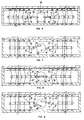
- the palisson comprises an upper plate 1 superimposed on a lower plate 2, these two plates having in correspondence on their faces opposite the teeth 3 to which correspond on the opposite plate cavities 4.
- the skin is intended to pass into the space between the two plates and is then subjected to a tensioning action exerted by the teeth 3 of said plates.
- the upper plate 1 is fixed by being made integral with the support structure 10 of the machine, while the lower plate 2 is movable.
- the displacement of this lower plate is obtained by means of one or more pairs of rods 5 'and 5'', oriented substantially vertically below said plate.
- the lower rod 5 '' is articulated at 6 to the fixed structure 10 of the machine, as well as at 7 at the lower end of the upper rod 5 '.
- the latter is itself articulated at 8 by its end opposite to the lower plate 2.
- a guide support 9 integral with the structure 10 of the machine and suitable for allowing said lower plate only a reciprocating movement oriented vertically.
- the fundamental condition for the functioning of the device lies in the fact that the upper rods, like the lower rods, must be arranged in parallel.
- the essential characteristic of the invention consists in the fact that the lower rods 5 '' are forced to perform an alternating movement centered on the hinge 6, so that the hinge 7 travels a short arc.
- the presence of the arm 11, in the case where more than one pair of rods has been provided, is essential to guarantee the concordance of the phases between the different pairs of rods, as well as to allow the setting in movement by means of a single device.
- a flywheel 12 is placed on which articulate at 13, symmetrically with respect to the axis of said flywheel, two auxiliary arms 14 whose opposite ends are articulated at 15 to the arms 11.
Landscapes
- Engineering & Computer Science (AREA)
- Manufacturing & Machinery (AREA)
- Mechanical Engineering (AREA)
- Chemical & Material Sciences (AREA)
- Organic Chemistry (AREA)
- Gripping Jigs, Holding Jigs, And Positioning Jigs (AREA)
- Transmission Devices (AREA)
- Fuel Cell (AREA)
- Press Drives And Press Lines (AREA)
- Disintegrating Or Milling (AREA)
- Spray Control Apparatus (AREA)
- Manipulator (AREA)
Claims (4)
- Stollmaschine, bestehend aus einer oberen Platte (1), die über einer unteren Platte (2) angeordnet ist, wobei die beiden Platten auf der Ebene ihrer einander gegenüberliegenden Flächen Zähne (3) enthalten, denen eine Reihe von Vertiefungen (4) auf der gegenüberliegenden Platte entsprechen, wobei die untere Platte (2) durch mindestens ein Paar unter dieser Platte vorgesehene Stangen (5' und 5'') im wesentlichen senkrecht zur Maschine verschiebbar ist, und wobei die Stange (5') ihrerseits durch ein Scharnier (8) mit der unteren Fläche der unteren Platte (2) verbunden ist, dadurch gekennzeichnet, daß die untere Stange (5'') durch ein Scharnier (6) mit der Fußplatte der Maschine verbunden ist, während sie mit ihrem oberen Ende mittels eines Scharniers (7) zur Führung der genannten Platte (2) mit der oberen Stange (5') verbunden ist, indem sie lediglich dieser Platte (2) gestattet, sich im senkrechten Sinne zu verschieben, wobei ein einzelner horizontal ausgerichteter Arm (11) vorgesehen ist, in den die verschiedenen Scharniere (7) eingesetzt sind, um die beiden Stangen (5' und 5'') eines Paares zu verbinden, wobei ein an zwei Hilfsarmen (14) befestigtes Schwungrad (12) dazu dient, eine abwechselnde Bewegung der Stange (5'') um das Scharnier (6) auszuführen, so daß das Scharnier (7) abwechselnd einen kurzen Kreisbogen durchläuft.
- Stollmaschine nach Anspruch 1, dadurch gekennzeichnet, daß sie unterhalb der beweglichen Platte (2) Mittel (16) besitzt, die dazu bestimmt sind, die Platte (2) gegen die obere Platte (1) zu drücken.
- Stollmaschine nach Anspruch 2, dadurch gekennzeichnet, daß die verschiedenen Paare von Stangen (5' und 5'') in zwei Gruppen unterteilt sind, die beidseitig des mittleren Teils der Maschine angeordnet sind, wobei die Stangenpaare jeder dieser Gruppen gegenseitig untereinander mittels eines Armes (11) verbunden sind, der die Scharniere (7) enthält, die die Stangen desselben Paares mit den im mittleren Teil der Maschine vorgesehen Mitteln (12, 13, 14, 15) verbinden, um die abwechselnde Bewegung der Annäherung und Entfernung beider Arme (11) durchzuführen.
- Stollmaschine nach Anspruch 3, dadurch gekennzeichnet, daß im mittleren Teil der Maschine ein Schwungrad (12) angeordnet ist, das sich um eine Horizontalachse dreht und an dem mittels Scharnieren (13), die symmetrisch in bezug auf die Achse des Schwungrades angeordnet sind, zwei Hilfsarme (14) befestigt sind, deren entgegengesetzte Enden durch Scharniere (15) mit den Enden der Arme (11) verbunden sind.
Applications Claiming Priority (2)
| Application Number | Priority Date | Filing Date | Title |
|---|---|---|---|
| IT8885615A IT1225579B (it) | 1988-07-15 | 1988-07-15 | Palissone. |
| IT8561588 | 1988-07-15 |
Publications (3)
| Publication Number | Publication Date |
|---|---|
| EP0351010A2 EP0351010A2 (de) | 1990-01-17 |
| EP0351010A3 EP0351010A3 (en) | 1990-07-11 |
| EP0351010B1 true EP0351010B1 (de) | 1994-09-28 |
Family
ID=11329025
Family Applications (1)
| Application Number | Title | Priority Date | Filing Date |
|---|---|---|---|
| EP89201811A Expired - Lifetime EP0351010B1 (de) | 1988-07-15 | 1989-07-07 | Stollmaschine |
Country Status (5)
| Country | Link |
|---|---|
| EP (1) | EP0351010B1 (de) |
| AT (1) | ATE112321T1 (de) |
| DE (1) | DE68918513T2 (de) |
| ES (1) | ES2063811T3 (de) |
| IT (1) | IT1225579B (de) |
Families Citing this family (2)
| Publication number | Priority date | Publication date | Assignee | Title |
|---|---|---|---|---|
| IT1280605B1 (it) * | 1995-11-06 | 1998-01-23 | Michele Zanette | Testa e macchina palissonatrice modulare, particolarmente per stirare ed ammorbidire pelli industriali e prodotti similari |
| IT1308153B1 (it) * | 1999-05-10 | 2001-11-29 | Cartigliano Off Spa | Macchina palissonatrice a piastre battenti. |
Family Cites Families (2)
| Publication number | Priority date | Publication date | Assignee | Title |
|---|---|---|---|---|
| DE282507C (de) * | ||||
| GB1448355A (en) * | 1975-03-07 | 1976-09-08 | Badische Maschf Gmbh | Sheet material processing |
-
1988
- 1988-07-15 IT IT8885615A patent/IT1225579B/it active
-
1989
- 1989-07-07 AT AT89201811T patent/ATE112321T1/de not_active IP Right Cessation
- 1989-07-07 ES ES89201811T patent/ES2063811T3/es not_active Expired - Lifetime
- 1989-07-07 DE DE68918513T patent/DE68918513T2/de not_active Expired - Fee Related
- 1989-07-07 EP EP89201811A patent/EP0351010B1/de not_active Expired - Lifetime
Also Published As
| Publication number | Publication date |
|---|---|
| IT8885615A0 (it) | 1988-07-15 |
| EP0351010A3 (en) | 1990-07-11 |
| DE68918513T2 (de) | 1995-04-20 |
| IT1225579B (it) | 1990-11-22 |
| DE68918513D1 (de) | 1994-11-03 |
| EP0351010A2 (de) | 1990-01-17 |
| ES2063811T3 (es) | 1995-01-16 |
| ATE112321T1 (de) | 1994-10-15 |
Similar Documents
| Publication | Publication Date | Title |
|---|---|---|
| FR2598347A1 (fr) | Tete de coupe et lame pour le decoupage de matieres en feuille | |
| FR2596319A1 (fr) | Appareil de bombage pour plieuse | |
| FR2596496A1 (fr) | Perfectionnements aux tetes de montage orientables et legeres, notamment pour appareils de prises de vue | |
| EP0366506A1 (de) | Zur Schleifbearbeitung von zylindrischen Lagerflächen von Werkstücken, insbesondere für die Bearbeitung von Kurbelwellen- und Kurbelzapfen mittels Bandschleifer | |
| CN218540648U (zh) | 一种建筑工程施工用液压振动夯实机 | |
| EP0070221B1 (de) | Druckverteilungseinrichtung für einen Werkzeugschlitten auf seine Führungsschiene | |
| EP0351010A2 (de) | Stollmaschine | |
| FR2693278A1 (fr) | Dispositif comportant un vibrateur fixé à un véhicule pour produire des vibrations sismiques. | |
| NL1029042C2 (nl) | Inrichting voor het tot voorbij de elasticiteitsgrens oprekken van de schalmen van een transmissieketting. | |
| EP0100926B1 (de) | Fahrzeug zur Handhabung von Materialien mit orientierbarem Ausleger und eingebautem Stabilisiergestell | |
| CN210649125U (zh) | 一种座椅型材焊接装置 | |
| FR2600634A1 (fr) | Dispositif de commande d'articulation de deux bras d'un e ngin | |
| EP0084504B1 (de) | Apparat zum Schleifen von Glaskanten | |
| CN207959103U (zh) | 扫雪刷举升装置 | |
| BE1001531A4 (fr) | Machine de sciage a cadre vertical. | |
| FR2467169A1 (fr) | Grue a tour | |
| SU927503A1 (ru) | Гидромеханический опрокидыватель дл подъема т желых опрокидных форм | |
| JPS6120116Y2 (de) | ||
| CN217675828U (zh) | 可调节的离型膜加工装置 | |
| CN113279443B (zh) | 一种铣槽机及铣槽机应用的成槽方法 | |
| FR2691127A1 (fr) | Appareil pour la rééducation ou le renforcement du sens de l'équilibre. | |
| CN210128830U (zh) | 一种自行车前叉用扭力测试设备 | |
| KR200371873Y1 (ko) | 이동형 운동기구 | |
| FR2594374A1 (fr) | Manipulateur pour pieces, charges et objets divers | |
| CN121231098A (zh) | 一种叉车转向桥耐久性试验台架及其试验方法 |
Legal Events
| Date | Code | Title | Description |
|---|---|---|---|
| PUAI | Public reference made under article 153(3) epc to a published international application that has entered the european phase |
Free format text: ORIGINAL CODE: 0009012 |
|
| AK | Designated contracting states |
Kind code of ref document: A2 Designated state(s): AT BE CH DE ES FR GB GR IT LI LU NL SE |
|
| PUAL | Search report despatched |
Free format text: ORIGINAL CODE: 0009013 |
|
| AK | Designated contracting states |
Kind code of ref document: A3 Designated state(s): AT BE CH DE ES FR GB GR IT LI LU NL SE |
|
| 17P | Request for examination filed |
Effective date: 19901214 |
|
| 17Q | First examination report despatched |
Effective date: 19921013 |
|
| RAP1 | Party data changed (applicant data changed or rights of an application transferred) |
Owner name: OFFICINE DI CARTIGLIANO S.P.A. |
|
| GRAA | (expected) grant |
Free format text: ORIGINAL CODE: 0009210 |
|
| AK | Designated contracting states |
Kind code of ref document: B1 Designated state(s): AT BE CH DE ES FR GB GR IT LI LU NL SE |
|
| PG25 | Lapsed in a contracting state [announced via postgrant information from national office to epo] |
Ref country code: NL Effective date: 19940928 Ref country code: GR Free format text: LAPSE BECAUSE OF FAILURE TO SUBMIT A TRANSLATION OF THE DESCRIPTION OR TO PAY THE FEE WITHIN THE PRESCRIBED TIME-LIMIT Effective date: 19940928 Ref country code: GB Effective date: 19940928 Ref country code: AT Effective date: 19940928 |
|
| REF | Corresponds to: |
Ref document number: 112321 Country of ref document: AT Date of ref document: 19941015 Kind code of ref document: T |
|
| REF | Corresponds to: |
Ref document number: 68918513 Country of ref document: DE Date of ref document: 19941103 |
|
| ITF | It: translation for a ep patent filed | ||
| PG25 | Lapsed in a contracting state [announced via postgrant information from national office to epo] |
Ref country code: SE Effective date: 19941228 |
|
| REG | Reference to a national code |
Ref country code: ES Ref legal event code: FG2A Ref document number: 2063811 Country of ref document: ES Kind code of ref document: T3 |
|
| NLV1 | Nl: lapsed or annulled due to failure to fulfill the requirements of art. 29p and 29m of the patents act | ||
| GBV | Gb: ep patent (uk) treated as always having been void in accordance with gb section 77(7)/1977 [no translation filed] |
Effective date: 19940928 |
|
| PLBE | No opposition filed within time limit |
Free format text: ORIGINAL CODE: 0009261 |
|
| STAA | Information on the status of an ep patent application or granted ep patent |
Free format text: STATUS: NO OPPOSITION FILED WITHIN TIME LIMIT |
|
| PG25 | Lapsed in a contracting state [announced via postgrant information from national office to epo] |
Ref country code: LU Free format text: LAPSE BECAUSE OF NON-PAYMENT OF DUE FEES Effective date: 19950731 Ref country code: LI Effective date: 19950731 Ref country code: CH Effective date: 19950731 Ref country code: BE Effective date: 19950731 |
|
| 26N | No opposition filed | ||
| BERE | Be: lapsed |
Owner name: OFFICINE DI CARTIGLIANO S.P.A. Effective date: 19950731 |
|
| REG | Reference to a national code |
Ref country code: CH Ref legal event code: PL |
|
| PG25 | Lapsed in a contracting state [announced via postgrant information from national office to epo] |
Ref country code: FR Effective date: 19960430 |
|
| REG | Reference to a national code |
Ref country code: FR Ref legal event code: ST |
|
| REG | Reference to a national code |
Ref country code: FR Ref legal event code: ST |
|
| REG | Reference to a national code |
Ref country code: FR Ref legal event code: ST |
|
| PGFP | Annual fee paid to national office [announced via postgrant information from national office to epo] |
Ref country code: ES Payment date: 20050706 Year of fee payment: 17 |
|
| PGFP | Annual fee paid to national office [announced via postgrant information from national office to epo] |
Ref country code: DE Payment date: 20050728 Year of fee payment: 17 |
|
| PGFP | Annual fee paid to national office [announced via postgrant information from national office to epo] |
Ref country code: IT Payment date: 20060731 Year of fee payment: 18 |
|
| PG25 | Lapsed in a contracting state [announced via postgrant information from national office to epo] |
Ref country code: DE Free format text: LAPSE BECAUSE OF NON-PAYMENT OF DUE FEES Effective date: 20070201 |
|
| REG | Reference to a national code |
Ref country code: ES Ref legal event code: FD2A Effective date: 20060708 |
|
| PG25 | Lapsed in a contracting state [announced via postgrant information from national office to epo] |
Ref country code: ES Free format text: LAPSE BECAUSE OF NON-PAYMENT OF DUE FEES Effective date: 20060708 |
|
| PG25 | Lapsed in a contracting state [announced via postgrant information from national office to epo] |
Ref country code: IT Free format text: LAPSE BECAUSE OF NON-PAYMENT OF DUE FEES Effective date: 20070707 |