EP0351060B1 - Bedienungspultsystem für Türsprechanlagen - Google Patents
Bedienungspultsystem für Türsprechanlagen Download PDFInfo
- Publication number
- EP0351060B1 EP0351060B1 EP19890305981 EP89305981A EP0351060B1 EP 0351060 B1 EP0351060 B1 EP 0351060B1 EP 19890305981 EP19890305981 EP 19890305981 EP 89305981 A EP89305981 A EP 89305981A EP 0351060 B1 EP0351060 B1 EP 0351060B1
- Authority
- EP
- European Patent Office
- Prior art keywords
- panel
- box
- control panel
- entryphones
- blocks
- Prior art date
- Legal status (The legal status is an assumption and is not a legal conclusion. Google has not performed a legal analysis and makes no representation as to the accuracy of the status listed.)
- Expired - Lifetime
Links
- 238000009434 installation Methods 0.000 claims description 17
- 230000009471 action Effects 0.000 claims description 4
- 238000005304 joining Methods 0.000 claims description 3
- 238000006073 displacement reaction Methods 0.000 claims description 2
- 230000000875 corresponding effect Effects 0.000 description 12
- 239000004020 conductor Substances 0.000 description 7
- 238000010276 construction Methods 0.000 description 4
- 238000004140 cleaning Methods 0.000 description 2
- 230000008878 coupling Effects 0.000 description 2
- 238000010168 coupling process Methods 0.000 description 2
- 238000005859 coupling reaction Methods 0.000 description 2
- 239000011521 glass Substances 0.000 description 2
- 238000005286 illumination Methods 0.000 description 2
- 238000010348 incorporation Methods 0.000 description 2
- 238000005192 partition Methods 0.000 description 2
- 230000001105 regulatory effect Effects 0.000 description 2
- 239000000470 constituent Substances 0.000 description 1
- 230000002596 correlated effect Effects 0.000 description 1
- 230000007812 deficiency Effects 0.000 description 1
- 230000000694 effects Effects 0.000 description 1
- 238000004519 manufacturing process Methods 0.000 description 1
- 230000000873 masking effect Effects 0.000 description 1
- 239000002184 metal Substances 0.000 description 1
- 239000000203 mixture Substances 0.000 description 1
- 230000000717 retained effect Effects 0.000 description 1
- 238000000926 separation method Methods 0.000 description 1
- 238000003860 storage Methods 0.000 description 1
Images



Classifications
-
- H—ELECTRICITY
- H04—ELECTRIC COMMUNICATION TECHNIQUE
- H04M—TELEPHONIC COMMUNICATION
- H04M11/00—Telephonic communication systems specially adapted for combination with other electrical systems
- H04M11/02—Telephonic communication systems specially adapted for combination with other electrical systems with bell or annunciator systems
- H04M11/025—Door telephones
-
- H—ELECTRICITY
- H04—ELECTRIC COMMUNICATION TECHNIQUE
- H04M—TELEPHONIC COMMUNICATION
- H04M1/00—Substation equipment, e.g. for use by subscribers
- H04M1/02—Constructional features of telephone sets
- H04M1/0291—Door telephones
Definitions
- This invention is concerned with a control panel system for entryphones.
- control panels for entryphones it is desirable, on one hand, to attain adequate functional characteristics, in the sense of providing a simple assembly and ease of technical manipulation, as well as a sufficient capacity of buttons, in acceptable dimensions while on the other hand there is importance to attain an aesthetic appearance in tune with the places in which the panels are to be situated, which is usually in the entrances of buildings.
- This proposal results in a compact structure, but one which is not properly speaking modular, since, as a function of the arrangement which each installation requires and of the number of buttons, it relies on distinct support profiles, of greater or lesser length, which creates a real manufacturing and storage problem. Also, this proposal has, inherently, only one button in each line of each column, so that for installations in buildings with many residences the control panel has to be very large.
- the present invention provides a control panel system for entryphones having a front panel of substantially constant cross-section with openings or windows for cardholders and push-buttons, or other working units of the entryphone, the panel being hinged on an installation box, characterised by caps, which secure the panel to the installation box by means of fasteners, the caps having covers which conceal the fasteners, and which are resiliently mounted on the caps so as to be displaceable relative thereto to allow access to the fasteners, and fastening means for holding the covers in position to conceal the fasteners.
- the system comprises pivotal members which provide lateral hinging of the panel on the box, so that said panel can swing sideways to give access to connections and elements inside the box.
- Advantageously studs are provided on the covers by which the covers are mounted on the caps for limited displacement under the action of resilient means and the fastening means.
- the panel is preferably composed from modular blocks which are joined together by means of rods which pass through the modular blocks, a laminar intermediate piece being provided between adjacent blocks, which piece separates the respective blocks and provides outside surface continuity for the front panel.
- the installation box is preferably formed from modular parts provided at their sides with hooking studs and casing recesses interengageable in such a way that the box can be assembled from the parts, the box further having recesses in the sides for the joining and housing of cable ducts, through which different boxes may be connected in parallel.
- the system may thus provide a simple control panel, in which all the integral parts are modular pieces or units, so that with a reduced number of distinct modular components, the construction and assembly of all the necessary kinds of control panels may be achieved in accordance with the multiplicity of different requirements for application installations.
- the panel offers moreover the possibility of a simple manipulation, both in assembly and for any necessary later adjustment in the integral working elements, since the opening by swinging towards the side allows easy access to all the internal elements, the necessary length of the connecting cables being minimal and without the panel being submitted at any time to unnecessary loads, as are produced in traditional arrangements, in which the panel is pivoted in a vertical plane.
- the particular constitution of the modular blocks which make up the card holders and buttons offers the possibility of installation of a large number of different buttons within a panel of considerably reduced size, which is extremely practical and very useful for buildings which contain a large number of residences with the same main entrance.
- buttons which may be made up with a grid-like box and a touch key which moves within the same, said key having a push spring, which is provided with internal touch conducting means and functions as a contact element, establishing at the point of contact a self-cleaning action which assures durable working, while said spring moreover fulfils the function of a collaborator in an opening for a connection in which a conductor cable must be clamped, thus facilitating connection of said cable.
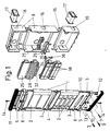
- FIG. 1 show a control panel system for an entryphone, in which a front panel is made essentially from a single section divided into modular blocks (1) of the desired length, said blocks having in front appropriate openings or windows (2) for the incorporation of cardholders and push-buttons, as well as for light and sound units, or whatever else has to be provided on the panel.
- each two adjacent modular section blocks (1) are joined together to form an integral structure, by means of longitudinal rods (3) long enough to link them at the sides, and inserted between each two adjacent modular section blocks (1) is a laminar intermediate piece (4), which by means of the rods (3) remains between the blocks, serving as a separation between the respective groups of the same, each intermediate piece (4) having on its outer edge a finish in harmony with the external face of the blocks (1), so that the panel, when assembled, offers surface continuity as if it were made from one piece.
- caps (5) by which a rigid connection of the structure is achieved, including on such caps (5) hinge members (6), which are mounted in such a way that on one of the sides (the left-hand side in Fig. 1) of the control panel they are pivoted to a rod (3) to swing on the rod.
- Each of the hinge members (6) is held by a screw (9) on a corresponding installation box (8), to which the control panel is thus attached like a door, able to be opened in a horizontal movement towards the side by turning on the pivots of the hinge members (6), while the configuration of these allows levelling of the control panel, by means of screws (7) which allow the position of the control panel to be regulated, both in its lateral “swinging", as well as in its projection towards the front, so that it is aligned and levelled.
- the caps (5) are provided with respective covering frames (11), which are mounted over the caps (5), engaging in them with studs (12) and with the interposition of springs (13), and secured by means of fixing screws (14), in such a way that when said screws (14) are tightened to their maximum, the springs (13) are compressed and the frames (11) cover the respective caps (5) hiding the heads of the fixing screws (9) and of other screws which pass through the same; but when the screws (14) are slackened, the frames (11) come away by themselves, as a result of the pressure from the springs (13), exposing the heads of the screws which were previously hidden, in order to effect opening of the panel, when access to the elements and connections inside is required or for other necessary operations.
- the installation box (8) is in its turn made up from modular units, whose joining together is achieved by means of a simple assembly of various pieces, their mutual attachment being assured, by the engaging of respective studs (15) of each one, in corresponding recesses in the other; while said modular units making up the box (8), have, in the sides, some recesses (16), in which are housed cable ducts (17), through which is achieved the colateral union between the different parallel boxes.
- Cardholders and call-buttons to be incorporated in the panel are integrated in modular blocks (18), each one of these blocks comprising a set number of cardholders and in relation to each one of these a pair of buttons at either side, making thus four push-buttons for each block (18).
- Said modular blocks (18) are composed, see Figure 2, of a structural body or frame (19), which has at its ends lugs (20) for fixing in the corresponding blocks (1) making up the panel, to whose frame is attached at the front a respective cover (21) which serves to hold the corresponding keys (22) of the push-buttons which project through it, each cover (21) defining between the respective openings for the keys (22) corresponding glasses (23) for the cardholders; while at the back the aforementioned frame (19) is closed in by cardholder backplates (24) of translucent plastic.
- each backplate (24) has a tongue (46) whose resilient housing in a recess (47) of one wall of those existing at the sides of a central partition of the frame (19) provides, in addition to some small flanges (49), for fixing of the cardholder backplates (24).
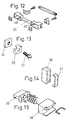
- this central partition there are also individual openings (45) into which penetrate, with a resilient coupling, studs (48) of a lampholder (25) shown in Figure 12, thus fixing the lampholder (25) centrally between the cardholders.
- the lampholders (25) are selectively distributed to establish adequate illumination of the cardholders.
- each block (18) defines housings (27) for the corresponding electrical connecting contacts.
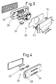
- the loudspeaker (28) and the light unit (29), are made up equally in respective modular blocks mountable in respective windows (2) of one of the blocks (1) of the constituent profile of the panel, see Figure 1, the respective bodies (30 and 31) of said units (28 and 29) having for that purpose appropriate fixing lugs (20) in a corresponding section of the profile (1), see Figures 3 and 4.
- a push-button (32) and that unit may comprise two potentiometers (51), see Figure 3, through which may be regulated the volume of sound both in the panel-telephone direction, and the opposite direction.
- the light unit (29) is provided in its case with its own appropriate lampholder (25), as that of the lampholders (25) of each of the different cardholders (23), so that thus on one hand, the necessary illumination for said cardholders (23) is obtained and, through the light unit (29) are illuminated signs or symbols such as the number of the door, name of a single family household, etc.
- the necessary blocks (18) and the units (28 and 29), or whatever else may be necessary are connected to the aforementioned blocks (18), by means of the contacts, see Figure 13, constituted by a screw (33) and a nut (34), between which is held a captive plate (35) like a box provided with appropriate recesses for the passage of the cables or terminals.
- said push spring (39) for the key (22) may extend along respective sections (40 and 41) in its ends, in such a way that one of said extensions, for example, section (40), is in a position to make contact with the conductor element (42) which makes up one of the connection terminals, when the key (22) is pressed; while the other section (41) exits through the bottom of the frame (19) and establishes a relation with the other connection terminal (43) formed by a screw and a captive plate, so that in said terminal (43) the aforementioned section (41) acts as a resilient collaborator to separate the captive plate from its seat when the screw is slackened, thus facilitating the introduction of the conductor cable (44) which is to be connected, while at the same time by means of said section (41), the spring (39) is for its part connected also to the aforementioned terminal (43).
- each key (22) comprises a one-piece plastic body which has a raised interior, to position and retain the spring (39) in reciprocity with a projection in the base of the housing which for the key (22) defines the frame (19).
- each key (22) may have a cover (50), made from a metal laminate which is positioned over the key (22) covering it up; this cover (50) is retained in its mounting by means of hooking established by the engagement of both of its side flanges, in respective housings in the key (22).
- FIG 15 is shown a push-button (32), which is provided in the unit (28), to illustrate its incorporation in a frame (38) according to a modular conception and how a spring is incorporated in an analogous solution to that of the call-buttons.
Landscapes
- Engineering & Computer Science (AREA)
- Signal Processing (AREA)
- Casings For Electric Apparatus (AREA)
- Bay Windows, Entrances, And Structural Adjustments Related Thereto (AREA)
Claims (5)
- Bedienfeldsystem für Eingangs-Sprechanlagen, das eine Vorderplatte (1) von im wesentlichen einheitlichem Querschnitt aufweist, die mit Öffnungen oder Fenstern (2) für Kartenhalter und Drucktasten oder sonstige Bedienelementen der Sprechanlage versehen ist, wobei die Platte (1) mit Schamieren an einem Installationskasten (8) befestigt ist, der gekennzeichnet ist durch Kappen (5) , die die Platte (1) am Installationskasten (8) mittels Befestigungsschrauben (7, 9) festhalten, wobei die Kappen (5) Abdeckungen (11), die die Befestigungsschrauben (7, 9) verdecken und die elastisch an den Kappen (5) angebracht sind, so daß sie von ihnen abgenommen werden können, um den Zugang zu den Befestigungsschrauben zu ermöglichen, sowie Befestigungsmittel (14) aufweisen, mit denen die Kappen (11) in einer Stellung gehalten werden, in der sie die Befestigungsschrauben (7, 9) verdecken.
- Bedienfeldsystem für Eingangs-Sprechanlagen nach Anspruch 1, gekennzeichnet durch Drehzapfen (6), die ein seitliches Einhängen der Platte am Kasten ermöglichen, so daß besagte Platte zur Seite gedreht werden und damit den Zugang zu den Anschlüssen und Elementen im Innern des Kastens freigeben kann.
- Bedienfeldsystem für Eingangs-Sprechanlagen nach Anspruch 1 oder 2, gekennzeichnet durch Stifte (12) auf den Abdeckungen (11), mittels derer die Abdeckungen auf den Kappen (5) so befestigt sind, daß sie durch die Betätigung des elastischen Mittels (13) und des Befestigungsmittels (14) in begrenztem Maße beiseitegedrückt werden können.
- Bedienfeldsystem für Eingangs-Sprechanlagen nach Anspruch 2 oder 3, gekennzeichnet dadurch, daß die Platte (1) aus modularen Blöcken besteht, die mittels durch die Modulblöcke geführten Stäben (3) zusammengehalten werden, wobei ein lamellenförmiges Zwischenstück (4) zwischen benachbarten Blöcken angebracht ist, wobei dieses Stück (4) die jeweiligen Blöcke voneinander trennt und der Vorderplatte (1) eine gleichmäßige Außenoberfläche verleiht.
- Bedienfeldsystem für Eingangs-Sprechanlagen nach jedem der vorhergehenden Ansprüche, gekennzeichnet dadurch, daß der Installationskasten (8) aus modularen Teilen gebildet wird, die an ihren Seiten mit Hakenstiften (15) und Gehäuseaussparungen versehen sind, die so ineinandergreifen, daß der Kasten (8) aus den Einzelteilen zusammengesetzt werden kann, wobei Kasten (8) weiterhin mit seitlichen Aussparungen (16) zur Befestigung und Umhüllung der Kabelstränge (17) versehen ist, mittels derer verschiedene Kästen parallel geschaltet werden können.
Applications Claiming Priority (2)
| Application Number | Priority Date | Filing Date | Title |
|---|---|---|---|
| ES8802179 | 1988-07-12 | ||
| ES8802179A ES2009616A6 (es) | 1988-07-12 | 1988-07-12 | Sistema de placa botonera para porteros automaticos. |
Publications (3)
| Publication Number | Publication Date |
|---|---|
| EP0351060A2 EP0351060A2 (de) | 1990-01-17 |
| EP0351060A3 EP0351060A3 (de) | 1991-03-06 |
| EP0351060B1 true EP0351060B1 (de) | 1994-12-14 |
Family
ID=8257264
Family Applications (1)
| Application Number | Title | Priority Date | Filing Date |
|---|---|---|---|
| EP19890305981 Expired - Lifetime EP0351060B1 (de) | 1988-07-12 | 1989-06-13 | Bedienungspultsystem für Türsprechanlagen |
Country Status (3)
| Country | Link |
|---|---|
| EP (1) | EP0351060B1 (de) |
| DE (1) | DE68919928T2 (de) |
| ES (1) | ES2009616A6 (de) |
Families Citing this family (7)
| Publication number | Priority date | Publication date | Assignee | Title |
|---|---|---|---|---|
| IT1223916B (it) * | 1988-11-18 | 1990-09-29 | Urmet Spa | Pulsantiera ad elementi modulari componibili particolarmente per impianti citofonici e videocitofonici |
| DE29717646U1 (de) * | 1997-10-05 | 1999-02-04 | HEWI Heinrich Wilke GmbH, 34454 Bad Arolsen | Informations- und Kommunikationseinrichtung |
| US6169651B1 (en) | 1998-06-05 | 2001-01-02 | General Electric Company | Protective relay with modular control panel |
| ES1046897Y (es) * | 2000-08-02 | 2001-12-16 | Guinaz S L | Elemento portador de conjunto de pulsadores para placa de portero automatico. |
| DE10316270B3 (de) * | 2003-04-08 | 2004-10-07 | Polo Industrie Gmbh | Mehrteilige Abdeckung für Elektroinstallationseinsätze |
| DE102007045870B4 (de) * | 2007-09-25 | 2012-01-05 | Albrecht Jung Gmbh & Co. Kg | Elektrisches/elektronisches Installationsgerät |
| JP7300289B2 (ja) * | 2019-03-22 | 2023-06-29 | アイホン株式会社 | インターホン機器 |
Family Cites Families (4)
| Publication number | Priority date | Publication date | Assignee | Title |
|---|---|---|---|---|
| FR2248563A1 (en) * | 1973-10-17 | 1975-05-16 | Diela | Entry phone system for blocks of flats - has separate call button microphone and loud speaker units joined together |
| ES237750Y (es) * | 1978-08-11 | 1979-03-16 | Cuerpo botonera perfeccionado, para porteros automaticos diovisuales | |
| DE3214435C1 (de) * | 1982-04-20 | 1983-08-11 | Ritto-Werk Loh GmbH & Co KG, 6348 Herborn | Sprechstelle für eine Sprechanlage |
| DE3441446A1 (de) * | 1983-11-21 | 1985-05-30 | LT Terraneo S.p.A., Erba, Como | Schalttafel nach dem baukastensystem |
-
1988
- 1988-07-12 ES ES8802179A patent/ES2009616A6/es not_active Expired
-
1989
- 1989-06-13 EP EP19890305981 patent/EP0351060B1/de not_active Expired - Lifetime
- 1989-06-13 DE DE1989619928 patent/DE68919928T2/de not_active Expired - Fee Related
Also Published As
| Publication number | Publication date |
|---|---|
| EP0351060A3 (de) | 1991-03-06 |
| DE68919928D1 (de) | 1995-01-26 |
| EP0351060A2 (de) | 1990-01-17 |
| ES2009616A6 (es) | 1989-10-01 |
| DE68919928T2 (de) | 1995-04-27 |
Similar Documents
| Publication | Publication Date | Title |
|---|---|---|
| US5658067A (en) | Modular light unit | |
| US7122740B2 (en) | Screwless switch plate assembly | |
| US4578739A (en) | Quick disconnect and function change radio assembly | |
| CN1061479A (zh) | 用于电脑外壳的门闩 | |
| US20060191697A1 (en) | Structured wiring box | |
| US3881071A (en) | Housing for a telephone unit | |
| EP0351060A2 (de) | Bedienungspultsystem für Türsprechanlagen | |
| US5475566A (en) | Interlocking housing and case assembly having a circuit board disposed parallel to a front panel | |
| US5402322A (en) | Modular wall-mounted equipment enclosure | |
| US4887972A (en) | Snap-together enclosure for a telephone jack receptacle | |
| US20030168881A1 (en) | Lock control assembly for a motor vehicle opening panel and opening panel equipped with same | |
| JP2001015788A (ja) | 太陽電池モジュールの配線構造 | |
| US3247352A (en) | Modular electrical components having means for side-by-side physical and electrical inter-connection | |
| KR20010021238A (ko) | 태양전지모듈의 배선구조 | |
| EP0849984A1 (de) | Modularer Schaltschrank | |
| EP0291524A1 (de) | Wandmontagesystem für datenübertragungsverbinder | |
| KR101800730B1 (ko) | 일체형 다중 스위치 | |
| CN218866537U (zh) | 一种防雨水门禁装置 | |
| CN217405845U (zh) | 一种装饰地插面板 | |
| CN210129368U (zh) | 一种弹簧锁扣及led显示屏 | |
| CN220904823U (zh) | 一种汽车阅读灯 | |
| JP2007044180A (ja) | 机 | |
| CN213115662U (zh) | 一种用于独立空间主体与封闭件装配的装配结构 | |
| CN2592834Y (zh) | 隔音门 | |
| JP3235052B2 (ja) | 両開きドアの召合せ下部水密構造 |
Legal Events
| Date | Code | Title | Description |
|---|---|---|---|
| PUAI | Public reference made under article 153(3) epc to a published international application that has entered the european phase |
Free format text: ORIGINAL CODE: 0009012 |
|
| AK | Designated contracting states |
Kind code of ref document: A2 Designated state(s): DE FR GB IT |
|
| PUAL | Search report despatched |
Free format text: ORIGINAL CODE: 0009013 |
|
| AK | Designated contracting states |
Kind code of ref document: A3 Designated state(s): DE FR GB IT |
|
| RHK1 | Main classification (correction) |
Ipc: H04M 1/02 |
|
| 17P | Request for examination filed |
Effective date: 19910618 |
|
| 17Q | First examination report despatched |
Effective date: 19930628 |
|
| GRAA | (expected) grant |
Free format text: ORIGINAL CODE: 0009210 |
|
| AK | Designated contracting states |
Kind code of ref document: B1 Designated state(s): DE FR GB IT |
|
| REF | Corresponds to: |
Ref document number: 68919928 Country of ref document: DE Date of ref document: 19950126 |
|
| ITF | It: translation for a ep patent filed | ||
| ET | Fr: translation filed | ||
| PLBE | No opposition filed within time limit |
Free format text: ORIGINAL CODE: 0009261 |
|
| STAA | Information on the status of an ep patent application or granted ep patent |
Free format text: STATUS: NO OPPOSITION FILED WITHIN TIME LIMIT |
|
| 26N | No opposition filed | ||
| PGFP | Annual fee paid to national office [announced via postgrant information from national office to epo] |
Ref country code: DE Payment date: 20010601 Year of fee payment: 13 |
|
| PGFP | Annual fee paid to national office [announced via postgrant information from national office to epo] |
Ref country code: FR Payment date: 20010606 Year of fee payment: 13 |
|
| PGFP | Annual fee paid to national office [announced via postgrant information from national office to epo] |
Ref country code: GB Payment date: 20010607 Year of fee payment: 13 |
|
| REG | Reference to a national code |
Ref country code: GB Ref legal event code: IF02 |
|
| PG25 | Lapsed in a contracting state [announced via postgrant information from national office to epo] |
Ref country code: GB Free format text: LAPSE BECAUSE OF NON-PAYMENT OF DUE FEES Effective date: 20020613 |
|
| PG25 | Lapsed in a contracting state [announced via postgrant information from national office to epo] |
Ref country code: DE Free format text: LAPSE BECAUSE OF NON-PAYMENT OF DUE FEES Effective date: 20030101 |
|
| GBPC | Gb: european patent ceased through non-payment of renewal fee |
Effective date: 20020613 |
|
| PG25 | Lapsed in a contracting state [announced via postgrant information from national office to epo] |
Ref country code: FR Free format text: LAPSE BECAUSE OF NON-PAYMENT OF DUE FEES Effective date: 20030228 |
|
| REG | Reference to a national code |
Ref country code: FR Ref legal event code: ST |
|
| PG25 | Lapsed in a contracting state [announced via postgrant information from national office to epo] |
Ref country code: IT Free format text: LAPSE BECAUSE OF NON-PAYMENT OF DUE FEES;WARNING: LAPSES OF ITALIAN PATENTS WITH EFFECTIVE DATE BEFORE 2007 MAY HAVE OCCURRED AT ANY TIME BEFORE 2007. THE CORRECT EFFECTIVE DATE MAY BE DIFFERENT FROM THE ONE RECORDED. Effective date: 20050613 |