EP0351104B1 - Hubschrauberrotorblatt - Google Patents
Hubschrauberrotorblatt Download PDFInfo
- Publication number
- EP0351104B1 EP0351104B1 EP89306634A EP89306634A EP0351104B1 EP 0351104 B1 EP0351104 B1 EP 0351104B1 EP 89306634 A EP89306634 A EP 89306634A EP 89306634 A EP89306634 A EP 89306634A EP 0351104 B1 EP0351104 B1 EP 0351104B1
- Authority
- EP
- European Patent Office
- Prior art keywords
- blade
- swept
- rotor
- tip
- edge
- Prior art date
- Legal status (The legal status is an assumption and is not a legal conclusion. Google has not performed a legal analysis and makes no representation as to the accuracy of the status listed.)
- Expired - Lifetime
Links
- 238000009826 distribution Methods 0.000 claims description 15
- 238000002156 mixing Methods 0.000 claims description 2
- 238000010586 diagram Methods 0.000 description 5
- 230000000694 effects Effects 0.000 description 3
- 238000011835 investigation Methods 0.000 description 3
- 238000013459 approach Methods 0.000 description 2
- 238000000926 separation method Methods 0.000 description 2
- 241000721701 Lynx Species 0.000 description 1
- 230000009471 action Effects 0.000 description 1
- 230000009286 beneficial effect Effects 0.000 description 1
- 230000015572 biosynthetic process Effects 0.000 description 1
- 230000008859 change Effects 0.000 description 1
- 125000004122 cyclic group Chemical group 0.000 description 1
- 238000011161 development Methods 0.000 description 1
- 238000006073 displacement reaction Methods 0.000 description 1
- 238000010348 incorporation Methods 0.000 description 1
- 230000007246 mechanism Effects 0.000 description 1
- 238000000034 method Methods 0.000 description 1
- 239000000203 mixture Substances 0.000 description 1
- 238000012986 modification Methods 0.000 description 1
- 230000004048 modification Effects 0.000 description 1
- 230000009467 reduction Effects 0.000 description 1
- 238000012360 testing method Methods 0.000 description 1
Images


Classifications
-
- B—PERFORMING OPERATIONS; TRANSPORTING
- B64—AIRCRAFT; AVIATION; COSMONAUTICS
- B64C—AEROPLANES; HELICOPTERS
- B64C27/00—Rotorcraft; Rotors peculiar thereto
- B64C27/32—Rotors
- B64C27/46—Blades
- B64C27/463—Blade tips
Definitions
- the angle of sweep of the swept extreme tip edge may be between 55 and 85 degrees from the blade feathering axis and preferably may be about 70 degrees from the blade feathering axis.
- rotor blade 11 As a lifting surface of bound vortex elements of equal strength.
- the main component of loading on blade 11 is determined by the incidence of the air flow approaching perpendicular to the leading edge 12 of the blade as indicated by arrows 19 and having a velocity component V N , and the lifting action of blade 11 is represented by a distribution of spanwise bound vortex elements 20 of equal strength ⁇ concentrated towards the leading edge 12 of blade 11 as shown.
- This concentration is because the centre of lift due to incidence on rotor blades at positions remote from the tip and other discontinuities is approximately the quarter chord, and the area ahead of the quarter chord should contain as many vortex elements as the area behind it to represent the lift.
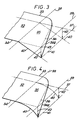
- FIG. 4 The diagram of Figure 4 is similar to that of Figure 3 except that the droop line 40 is a gently downwardly curved line resulting in a maximum deflection 42 similar to that of Figure 3, and the resulting curved droop surface is termed herein a curved anhedral droop.
Landscapes
- Engineering & Computer Science (AREA)
- Mechanical Engineering (AREA)
- Aviation & Aerospace Engineering (AREA)
- Structures Of Non-Positive Displacement Pumps (AREA)
- Toys (AREA)
Claims (21)
- Hubschrauberrotorblatt (32, 45) mit einem Wurzelende (50) zur Befestigung an einem Rotorkopf, einem mittleren Abschnitt (46), der sich vom Wurzelende aus erstreckt und Tragflügelquerschnitt mit einer Vorder- (33, 47) und Hinterkante (34, 48) sowie eine Blattiefenabmessung (44) hat, und einer gepfeilten Spitze (35, 51) am Ende des mittleren Abschnitts gegenüber dem Wurzelende, welches eine Blattspannweite festlegt, wobei die gepfeilte Spitze eine gepfeilte, äußerste Endkante (36, 56) aufweist, dadurch gekennzeichnet, daß die gepfeilte, äußerste Endkante einen abfallenden Blattverlauf (40) aufweist, um die gebundene Wirbelverteilung, die durch Luftströmung in Spannweitenrichtung über die gepfeilte, äußerste Endkante erzeugt wird, zu verändern, um aerodynamische Kippmomente des Blatts in den in Längsrichtung liegenden Sektoren des Rotorkreises während des Vorwärtsfluges eines Hubschraubers, an dem das Blatt angebracht ist, zu vermindern.
- Rotorblatt nach Anspruch 1, dadurch gekennzeichnet, daß der abfallende Blattverlauf aus einer ebenen, abfallenden V-Stellung besteht.
- Rotorblatt nach Anspruch 1, dadurch gekennzeichnet, daß der abfallende Blattverlauf aus einem konisch zulaufenden, gewölbten, abfallenden Blattverlauf besteht.
- Rotorblatt nach einem der vorangehenden Ansprüche, dadurch gekennzeichnet, daß das Profil des abfallenden Blattverlaufs durch Projektion der Grundrißform der Blattspitze auf eine abfallende Fläche festgelegt wird, die aus abfallenden Linien (40) geometrisch ähnlicher Form besteht, die in zu einer Blattverstellachse (37, 52) parallelen Ebenen angeordnet sind, und sich zwischen einer ersten, in Blattiefenrichtung verlaufenden Bezugsachse (38, 59) weiter innenliegend als die Blattspitze und einer zweiten, in Blattiefenrichtung verlaufenden Bezugsachse (39) weiter außenliegend als die erste Achse erstrecken.
- Rotorblatt nach Anspruch 4, dadurch gekennzeichnet, daß die erste Bezugsachse (38, 59) senkrecht zu einer Blattverstellachse (37, 52) ist.
- Rotorblatt nach Anspruch 5, dadurch gekennzeichnet, daß die erste Bezugsachse (38) bei etwa 95 % der Blattspannweite angeordnet ist.
- Rotorblatt nach einem der Ansprüche 4 bis 6, dadurch gekennzeichnet, daß die zweite Bezugsachse (39) senkrecht zu der Blattverstellachse (37) ist.
- Rotorblatt nach Anspruch 7, dadurch gekennzeichnet, daß die zweite Bezugsachse (39) bei 100 % der Blattspannweite angeordnet ist.
- Rotorblatt nach Anspruch 4 oder 5, dadurch gekennzeichnet, daß die zweite Bezugsachse (39) unter einem Winkel zur Blattverstellachse (37) verläuft, so daß ihre Verlängerung die erste Bezugsachse (38) in einem Punkt vor der Blattvorderkante (33) schneidet.
- Rotorblatt nach Anspruch 9, dadurch gekennzeichnet, daß der Winkel der zweiten Bezugsachse (39) im wesentlichen der gleiche wie der Pfeilungswinkel der gepfeilten, äußersten Endkante (36) ist.
- Rotorblatt nach Anspruch 10, dadurch gekennzeichnet, daß die zweite Bezugsachse (39) mit der gepfeilten, äußersten Endkante (36) zusammenfällt.
- Rotorblatt nach einem der Ansprüche 4 bis 11, dadurch gekennzeichnet, daß die besagte abfallende Fläche eben ist.
- Rotorblatt nach Anspruch 12, dadurch gekennzeichnet, daß sich die abfallende Fläche nach unten und nach außen von der ersten Bezugsachse (38) und unter einem Winkel von etwa 20° erstreckt.
- Rotorblatt nach einem der Ansprüche 4 bis 11, dadurch gekennzeichnet, daß die abfallende Fläche gebogen ist.
- Rotorblatt nach einem der vorangehenden Ansprüche, dadurch gekennzeichnet, daß der Pfeilungswinkel der gepfeilten, äußersten Endkante (36, 56) zwischen 55 und 85° gegenüber der Blattverstellachse (37, 52) beträgt.
- Rotorblatt nach einem der vorangehenden Ansprüche, dadurch gekennzeichnet, daß der Pfeilungswinkel der gepfeilten, äußersten Endkante (36, 56) etwa 70° gegenüber der Blattverstellachse (37, 52) beträgt.
- Hubschrauberrotorblatt (52, 45) mit einem Wurzelende (50), das dazu bestimmt ist, beim Betrieb an einem Rotorkopf zur Drehung um eine im allgemeinen vertikale Achse befestigt zu werden, um einen Rotorkreis festzulegen, einem mittleren Abschnitt (46), der sich vom Wurzelende aus erstreckt und einen Tragflügelquerschnitt mit einer Vorder- (33, 47) und einer Hinterkante (34, 48) und einer Blattiefenabmessung (44) aufweist, und einer gepfeilten Spitze (35, 51) am Ende des mittleren Abschnitts, die eine Blattspannweite festlegt und eine gepfeilte, äußerste Endkante (36, 56) aufweist, dadurch gekennzeichnet, daß senkrecht zu der gepfeilten, äußersten Endkante (36, 56) liegende Blattquerschnitte Tragflügelquerschnitte mit einem vorbestimmten, gepfeilten, abfallenden Blattspitzenverlauf (40) sind, der die Luftströmungseigenschaften um die gepfeilte Spitze (35, 51) festlegt, um aerodynamische Kippmomente zu vermindern, die aufgrund einer Luftströmung in Spannweitenrichtung auftreten, die in den in Längsrichtung liegenden Sektoren des Rotorkreises beim Vorwärtsflug eines Hubschraubers auftreten, an dem das Rotorblatt angebracht ist.
- Hubschrauberrotorblatt (45), umfassend ein Wurzelende (50) zur Befestigung an einem Rotorkopf zur Drehung während des Betriebs um eine im allgemeinen vertikale Achse, um einen Rotorkreis festzulegen, einen zentralen Abschnitt (46), der sich vom Wurzelende aus erstreckt und Tragflügelquerschnitt mit einer Vorder- (47) und Hinterkante (48) sowie einer Blattiefenrichtung (49) hat, eine gepfeilte Spitze (51) am Ende des mittleren Abschnitts gegenüber dem Wurzelende mit einem ersten Vorderkantenbereich (53), der sich von einer Verbindung mit der Vorderkante des mittleren Bereichs zu einem ersten Punkt erstreckt, welcher vor der Vorderkante des mittleren Bereichs liegt, mit einem zweiten Vorderkantenbereich (54), der von dem ersten Punkt zu einem zweiten Punkt rückwärts gepfeilt ist, einer rückwärts gepfeilten, äußersten Endkante (56), deren Pfeilung größer ist als die des zweiten Vorderkantenbereichs und die sich zu einem dritten Punkt (57) erstreckt, einem gekrümmten Anschlußbereich (55), in dem der zweite Vorderkantenbereich in die Endkante übergeht, und einer rückwärts gepfeilten Hinterkante (58), die sich von einer Verbindung mit der Hinterkante des mittleren Abschnitts zum dritten Punkt erstreckt, wobei die gepfeilte Spitze eine Blattiefenabmessung hat, die größer ist als die Blattiefenabmessung des mittleren Abschnitts, und wobei die Dicke einer äußeren Zone der Spitze zur gepfeilten, äußersten Endkante hin allmählich abnimmt, dadurch gekennzeichnet, daß die gepfeilte Spitze hinsichtlich des Rotorkreises im Bereich der gepfeilten, äußersten Endkante nach unten ausgelenkt ist, um aerodynamische Kippmomente zu reduzieren, die von der gepfeilten, äußersten Endkante aufgrund einer Luftströmung in Spannweitenrichtung stammen, welche in den in Längsrichtung liegenden Sektoren des Rotorkreises beim Vorwärtsflug eines Hubschraubers, an dem das Blatt angebracht ist, auftritt.
- Rotorblatt nach Anspruch 18, dadurch gekennzeichnet, daß der zweite Vorderkantenbereich (54) bei einer Blattstation von etwa 0,87 R beginnt, und daß die nach unten ausgelenkte, gepfeilte, äußerste Endkante (56) bei etwa 0,95 R beginnt.
- Haupttragrotor eines Hubschraubers, dadurch gekennzeichnet, daß dieser eine Anzahl von Rotorblättern gemäß einem der vorangehenden Ansprüche aufweist.
- Hubschrauber, gekennzeichnet durch einen Haupttragrotor nach Anspruch 20.
Applications Claiming Priority (2)
| Application Number | Priority Date | Filing Date | Title |
|---|---|---|---|
| GB8815955 | 1988-07-05 | ||
| GB888815955A GB8815955D0 (en) | 1988-07-05 | 1988-07-05 | Helicopter rotor blades |
Publications (3)
| Publication Number | Publication Date |
|---|---|
| EP0351104A2 EP0351104A2 (de) | 1990-01-17 |
| EP0351104A3 EP0351104A3 (en) | 1990-09-26 |
| EP0351104B1 true EP0351104B1 (de) | 1995-06-07 |
Family
ID=10639881
Family Applications (1)
| Application Number | Title | Priority Date | Filing Date |
|---|---|---|---|
| EP89306634A Expired - Lifetime EP0351104B1 (de) | 1988-07-05 | 1989-06-29 | Hubschrauberrotorblatt |
Country Status (8)
| Country | Link |
|---|---|
| US (1) | US4975022A (de) |
| EP (1) | EP0351104B1 (de) |
| JP (1) | JP2933949B2 (de) |
| AU (1) | AU614857B2 (de) |
| CA (1) | CA1326228C (de) |
| DE (1) | DE68922937T2 (de) |
| ES (1) | ES2072301T3 (de) |
| GB (1) | GB8815955D0 (de) |
Cited By (1)
| Publication number | Priority date | Publication date | Assignee | Title |
|---|---|---|---|---|
| US10899440B2 (en) | 2017-03-09 | 2021-01-26 | Sikorsky Aircraft Corporation | Rotor blade tip design for improved hover and cruise performance |
Families Citing this family (34)
| Publication number | Priority date | Publication date | Assignee | Title |
|---|---|---|---|---|
| JP2525836Y2 (ja) * | 1989-03-29 | 1997-02-12 | 川崎重工業株式会社 | 回転翼用ブレードの先端部形状 |
| GB9023141D0 (en) * | 1990-10-24 | 1991-07-10 | Westland Helicopters | Helicopter rotor blades |
| US5297759A (en) * | 1992-04-06 | 1994-03-29 | Neil Tilbor | Rotary aircraft passively stable in hover |
| FR2689852B1 (fr) * | 1992-04-09 | 1994-06-17 | Eurocopter France | Pale pour voilure tournante d'aeronef, a extremite en fleche. |
| DE4400806A1 (de) * | 1994-01-13 | 1995-07-20 | Bernd Stolz | Propeller |
| US5634613A (en) * | 1994-07-18 | 1997-06-03 | Mccarthy; Peter T. | Tip vortex generation technology for creating a lift enhancing and drag reducing upwash effect |
| US5634839A (en) * | 1994-11-23 | 1997-06-03 | Donald Dixon | Toy aircraft and method for remotely controlling same |
| US5672086A (en) * | 1994-11-23 | 1997-09-30 | Dixon; Don | Aircraft having improved auto rotation and method for remotely controlling same |
| GB9600123D0 (en) | 1996-01-04 | 1996-03-06 | Westland Helicopters | Aerofoil |
| DE29602559U1 (de) * | 1996-02-14 | 1996-04-18 | Kähler, Kai, 20355 Hamburg | Drehflügelluftfahrzeug |
| GB2312712A (en) * | 1996-04-30 | 1997-11-05 | Gkn Westland Helicopters Ltd | Propeller/rotor blade |
| JP3170470B2 (ja) * | 1997-03-24 | 2001-05-28 | 株式会社コミュータヘリコプタ先進技術研究所 | 回転翼機のロータブレード |
| JP3916723B2 (ja) | 1997-05-15 | 2007-05-23 | 富士重工業株式会社 | 回転翼航空機の回転翼羽根 |
| US6260809B1 (en) * | 2000-04-05 | 2001-07-17 | United Technologies Corporation | Ovate loop for rotary-wing blades |
| US6497385B1 (en) * | 2000-11-08 | 2002-12-24 | Continuum Dynamics, Inc. | Rotor blade with optimized twist distribution |
| US7207526B2 (en) * | 2002-06-26 | 2007-04-24 | Mccarthy Peter T | High efficiency tip vortex reversal and induced drag reduction |
| AU2003249321B2 (en) | 2002-07-19 | 2010-02-18 | Peter T. Mccarthy | Propulsion hydrofoils |
| US20050061921A1 (en) * | 2003-09-19 | 2005-03-24 | Egolf Thomas A. | Aerodynamic tip protuberances for tip vortex intensity reduction |
| US7475848B2 (en) * | 2003-11-11 | 2009-01-13 | Morgenstern John M | Wing employing leading edge flaps and winglets to achieve improved aerodynamic performance |
| GB0420601D0 (en) * | 2004-09-16 | 2004-10-20 | Qinetiq Ltd | Wing tip devices |
| US8066219B2 (en) * | 2008-04-25 | 2011-11-29 | Karem Aircraft, Inc. | Anhedral tip blades for tiltrotor aircraft |
| ES3040742T3 (en) | 2008-06-20 | 2025-11-04 | Aviation Partners Inc | Curved wing tip |
| DE102009012801B4 (de) * | 2009-03-13 | 2012-04-05 | Eads Deutschland Gmbh | Anisotrope Betätigung einer Helikopterrotorblattspitze |
| JP5693842B2 (ja) * | 2009-12-14 | 2015-04-01 | 独立行政法人 宇宙航空研究開発機構 | ヘリコプタのロータ・ブレード |
| US20120128501A1 (en) * | 2010-11-23 | 2012-05-24 | 4Front Engineered Solutions, Inc. | Fan blade tips |
| GB2486021B (en) * | 2010-12-02 | 2017-07-19 | Agustawestland Ltd | Aerofoil |
| US8842000B2 (en) | 2012-07-17 | 2014-09-23 | 4Front Engineered Solutions, Inc. | Fire control systems |
| US9874214B2 (en) | 2014-01-28 | 2018-01-23 | 4Front Engineered Solutions, Inc. | Fan with fan blade mounting structure |
| US9726192B2 (en) | 2015-03-31 | 2017-08-08 | Assa Abloy Entrance Systems Ab | Fan blades and associated blade tips |
| US10358926B2 (en) * | 2017-08-11 | 2019-07-23 | General Electric Company | Low-noise airfoil for an open rotor |
| CN108583871A (zh) * | 2018-06-25 | 2018-09-28 | 李竟儒 | 一种使直升飞机气流上升的旋翼 |
| US20200039641A1 (en) * | 2018-08-02 | 2020-02-06 | Bell Helicopter Textron Inc. | Abrasion strip and method of manufacturing the same |
| US11440644B2 (en) * | 2020-02-21 | 2022-09-13 | Textron Innovations Inc. | Download reducing winglets for aircraft having a rotor producing downwash and method of operating the same |
| US12448111B1 (en) * | 2024-04-17 | 2025-10-21 | Textron Innovations Inc. | Method and system for inverse-tapered high-speed rotors |
Family Cites Families (10)
| Publication number | Priority date | Publication date | Assignee | Title |
|---|---|---|---|---|
| US3411738A (en) * | 1966-10-27 | 1968-11-19 | William E. Sargent | Airfoil tip |
| US3399731A (en) | 1967-07-18 | 1968-09-03 | Algy F. Giles Jr. | Rotor-blade |
| US3822105A (en) * | 1971-09-22 | 1974-07-02 | United Aircraft Corp | Helicopter blade |
| AU497939B2 (en) * | 1974-04-19 | 1979-01-25 | United Aircraft Corporation | Helicopter blade |
| GB1538055A (en) * | 1975-05-19 | 1979-01-10 | Westland Aircraft Ltd | Helicopter rotor blades |
| US4324530A (en) * | 1980-01-21 | 1982-04-13 | United Technologies Corp. | Helicopter blade with a tip having a selected combination of sweep, taper and anhedral to improve hover efficiency |
| US4334828A (en) * | 1980-01-21 | 1982-06-15 | United Technologies Corporation | Helicopter blade with a tip having a selected combination of sweep, taper and anhedral to improve hover efficiency |
| US4477042A (en) * | 1981-01-19 | 1984-10-16 | Griswold Ii Roger W | Vortex alleviating wing tip |
| FR2507149A1 (fr) * | 1981-06-05 | 1982-12-10 | Onera (Off Nat Aerospatiale) | Extremite de pale pour voilure tournante d'aeronef et voilure tournante pourvue de telles extremites de pale |
| FR2617118B1 (fr) * | 1987-06-29 | 1992-08-21 | Aerospatiale | Pale a extremite courbe pour voilure tournante d'aeronef |
-
1988
- 1988-07-05 GB GB888815955A patent/GB8815955D0/en active Pending
-
1989
- 1989-06-27 US US07/371,848 patent/US4975022A/en not_active Expired - Lifetime
- 1989-06-29 EP EP89306634A patent/EP0351104B1/de not_active Expired - Lifetime
- 1989-06-29 DE DE68922937T patent/DE68922937T2/de not_active Expired - Fee Related
- 1989-06-29 ES ES89306634T patent/ES2072301T3/es not_active Expired - Lifetime
- 1989-07-04 CA CA000604664A patent/CA1326228C/en not_active Expired - Lifetime
- 1989-07-05 JP JP1172094A patent/JP2933949B2/ja not_active Expired - Lifetime
- 1989-07-05 AU AU37895/89A patent/AU614857B2/en not_active Ceased
Cited By (1)
| Publication number | Priority date | Publication date | Assignee | Title |
|---|---|---|---|---|
| US10899440B2 (en) | 2017-03-09 | 2021-01-26 | Sikorsky Aircraft Corporation | Rotor blade tip design for improved hover and cruise performance |
Also Published As
| Publication number | Publication date |
|---|---|
| AU614857B2 (en) | 1991-09-12 |
| JPH0260898A (ja) | 1990-03-01 |
| ES2072301T3 (es) | 1995-07-16 |
| DE68922937D1 (de) | 1995-07-13 |
| EP0351104A3 (en) | 1990-09-26 |
| GB8815955D0 (en) | 1988-11-16 |
| US4975022A (en) | 1990-12-04 |
| AU3789589A (en) | 1990-01-11 |
| JP2933949B2 (ja) | 1999-08-16 |
| CA1326228C (en) | 1994-01-18 |
| EP0351104A2 (de) | 1990-01-17 |
| DE68922937T2 (de) | 1996-02-08 |
Similar Documents
| Publication | Publication Date | Title |
|---|---|---|
| EP0351104B1 (de) | Hubschrauberrotorblatt | |
| CA1143354A (en) | Helicopter blade with a tip having a selected combination of sweep, taper, and anhedral to improve hover efficiency | |
| JP3802209B2 (ja) | 航空機回転翼のための後退翼端付きの羽根 | |
| US5174721A (en) | Helicopter rotor blades | |
| JP2624785B2 (ja) | 航空機の回転翼の羽根 | |
| US8066219B2 (en) | Anhedral tip blades for tiltrotor aircraft | |
| EP0482932B1 (de) | Rotorblätter eines Drehflügelflugzeuges | |
| EP0615903B1 (de) | Drehbare Blätter | |
| US4334828A (en) | Helicopter blade with a tip having a selected combination of sweep, taper and anhedral to improve hover efficiency | |
| EP0878394B1 (de) | Rotorblatt eines Drehflügelflugzeuges | |
| US6260809B1 (en) | Ovate loop for rotary-wing blades | |
| EP3774528B1 (de) | Flügelspitzen sowie flügelspitzenkonstruktions- und entwurfsverfahren | |
| CA1295310C (en) | Helicopter blade airfoil | |
| US10899440B2 (en) | Rotor blade tip design for improved hover and cruise performance | |
| US5927948A (en) | Propeller | |
| US5205715A (en) | Helicopter rotor blades | |
| US20040042901A1 (en) | Extreme mu rotor | |
| US5246344A (en) | Helicopter rotor blade with improved performance characteristics | |
| CA1078357A (en) | Torsionally compliant helicopter rotor blade with improved stability and performance characteristics | |
| US20050281676A1 (en) | Multi-hedral rotary wing | |
| US6364615B1 (en) | Blade for the rotary wings of an aircraft | |
| JP7674379B2 (ja) | ヘリコプタ、ヘリコプタキット及び関連する再構成方法 | |
| CA2348677A1 (en) | Rotor for rotary wing aircraft | |
| JP2852031B2 (ja) | 回転翼機のロータブレード |
Legal Events
| Date | Code | Title | Description |
|---|---|---|---|
| PUAI | Public reference made under article 153(3) epc to a published international application that has entered the european phase |
Free format text: ORIGINAL CODE: 0009012 |
|
| AK | Designated contracting states |
Kind code of ref document: A2 Designated state(s): DE ES FR GB GR IT NL |
|
| RBV | Designated contracting states (corrected) |
Designated state(s): DE ES FR GB IT NL |
|
| PUAL | Search report despatched |
Free format text: ORIGINAL CODE: 0009013 |
|
| AK | Designated contracting states |
Kind code of ref document: A3 Designated state(s): DE ES FR GB GR IT NL |
|
| 17P | Request for examination filed |
Effective date: 19910225 |
|
| 17Q | First examination report despatched |
Effective date: 19920827 |
|
| GRAA | (expected) grant |
Free format text: ORIGINAL CODE: 0009210 |
|
| ITF | It: translation for a ep patent filed | ||
| AK | Designated contracting states |
Kind code of ref document: B1 Designated state(s): DE ES FR GB IT NL |
|
| REF | Corresponds to: |
Ref document number: 68922937 Country of ref document: DE Date of ref document: 19950713 |
|
| REG | Reference to a national code |
Ref country code: ES Ref legal event code: FG2A Ref document number: 2072301 Country of ref document: ES Kind code of ref document: T3 |
|
| ET | Fr: translation filed | ||
| PLBE | No opposition filed within time limit |
Free format text: ORIGINAL CODE: 0009261 |
|
| STAA | Information on the status of an ep patent application or granted ep patent |
Free format text: STATUS: NO OPPOSITION FILED WITHIN TIME LIMIT |
|
| 26N | No opposition filed | ||
| PGFP | Annual fee paid to national office [announced via postgrant information from national office to epo] |
Ref country code: NL Payment date: 19960626 Year of fee payment: 8 |
|
| PGFP | Annual fee paid to national office [announced via postgrant information from national office to epo] |
Ref country code: DE Payment date: 19960627 Year of fee payment: 8 Ref country code: ES Payment date: 19960627 Year of fee payment: 8 |
|
| PG25 | Lapsed in a contracting state [announced via postgrant information from national office to epo] |
Ref country code: ES Free format text: LAPSE BECAUSE OF NON-PAYMENT OF DUE FEES Effective date: 19970630 |
|
| PG25 | Lapsed in a contracting state [announced via postgrant information from national office to epo] |
Ref country code: NL Effective date: 19980101 |
|
| NLV4 | Nl: lapsed or anulled due to non-payment of the annual fee |
Effective date: 19980101 |
|
| PG25 | Lapsed in a contracting state [announced via postgrant information from national office to epo] |
Ref country code: DE Free format text: LAPSE BECAUSE OF NON-PAYMENT OF DUE FEES Effective date: 19980303 |
|
| REG | Reference to a national code |
Ref country code: ES Ref legal event code: FD2A Effective date: 20000403 |
|
| REG | Reference to a national code |
Ref country code: GB Ref legal event code: IF02 |
|
| PGFP | Annual fee paid to national office [announced via postgrant information from national office to epo] |
Ref country code: FR Payment date: 20070608 Year of fee payment: 19 |
|
| PGFP | Annual fee paid to national office [announced via postgrant information from national office to epo] |
Ref country code: IT Payment date: 20080625 Year of fee payment: 20 |
|
| PGFP | Annual fee paid to national office [announced via postgrant information from national office to epo] |
Ref country code: GB Payment date: 20080702 Year of fee payment: 20 |
|
| REG | Reference to a national code |
Ref country code: FR Ref legal event code: ST Effective date: 20090228 |
|
| REG | Reference to a national code |
Ref country code: FR Ref legal event code: D3 |
|
| REG | Reference to a national code |
Ref country code: GB Ref legal event code: PE20 Expiry date: 20090628 |
|
| PG25 | Lapsed in a contracting state [announced via postgrant information from national office to epo] |
Ref country code: FR Free format text: LAPSE BECAUSE OF NON-PAYMENT OF DUE FEES Effective date: 20080630 |
|
| PG25 | Lapsed in a contracting state [announced via postgrant information from national office to epo] |
Ref country code: GB Free format text: LAPSE BECAUSE OF EXPIRATION OF PROTECTION Effective date: 20090628 |