EP0351188B1 - Verfahren zur Umwandlung von Farbendaten einer Lichtquelle und Farbendaten eines nichtleuchtenden Objektes - Google Patents
Verfahren zur Umwandlung von Farbendaten einer Lichtquelle und Farbendaten eines nichtleuchtenden Objektes Download PDFInfo
- Publication number
- EP0351188B1 EP0351188B1 EP89307028A EP89307028A EP0351188B1 EP 0351188 B1 EP0351188 B1 EP 0351188B1 EP 89307028 A EP89307028 A EP 89307028A EP 89307028 A EP89307028 A EP 89307028A EP 0351188 B1 EP0351188 B1 EP 0351188B1
- Authority
- EP
- European Patent Office
- Prior art keywords
- color
- light
- source
- crt monitor
- luminous object
- Prior art date
- Legal status (The legal status is an assumption and is not a legal conclusion. Google has not performed a legal analysis and makes no representation as to the accuracy of the status listed.)
- Expired - Lifetime
Links
- 238000000034 method Methods 0.000 title claims description 23
- 230000001131 transforming effect Effects 0.000 title claims description 12
- 230000003595 spectral effect Effects 0.000 claims description 39
- 238000009826 distribution Methods 0.000 claims description 17
- 230000000007 visual effect Effects 0.000 claims description 15
- OAICVXFJPJFONN-UHFFFAOYSA-N Phosphorus Chemical compound [P] OAICVXFJPJFONN-UHFFFAOYSA-N 0.000 claims description 8
- 230000006870 function Effects 0.000 claims description 8
- 238000011426 transformation method Methods 0.000 claims description 7
- 238000012937 correction Methods 0.000 claims description 3
- 239000003086 colorant Substances 0.000 description 18
- 230000009466 transformation Effects 0.000 description 9
- 238000005516 engineering process Methods 0.000 description 6
- 238000005259 measurement Methods 0.000 description 6
- 230000005540 biological transmission Effects 0.000 description 4
- 238000013461 design Methods 0.000 description 4
- 238000010586 diagram Methods 0.000 description 4
- 238000012360 testing method Methods 0.000 description 3
- 238000005286 illumination Methods 0.000 description 2
- 235000019557 luminance Nutrition 0.000 description 2
- 238000004519 manufacturing process Methods 0.000 description 2
- 239000011159 matrix material Substances 0.000 description 2
- 230000003287 optical effect Effects 0.000 description 2
- 238000000844 transformation Methods 0.000 description 2
- 210000001072 colon Anatomy 0.000 description 1
- 230000004456 color vision Effects 0.000 description 1
- 238000004737 colorimetric analysis Methods 0.000 description 1
- 230000004313 glare Effects 0.000 description 1
- 238000003384 imaging method Methods 0.000 description 1
- 230000008447 perception Effects 0.000 description 1
Images


Classifications
-
- G—PHYSICS
- G01—MEASURING; TESTING
- G01J—MEASUREMENT OF INTENSITY, VELOCITY, SPECTRAL CONTENT, POLARISATION, PHASE OR PULSE CHARACTERISTICS OF INFRARED, VISIBLE OR ULTRAVIOLET LIGHT; COLORIMETRY; RADIATION PYROMETRY
- G01J3/00—Spectrometry; Spectrophotometry; Monochromators; Measuring colours
- G01J3/46—Measurement of colour; Colour measuring devices, e.g. colorimeters
-
- G—PHYSICS
- G01—MEASURING; TESTING
- G01J—MEASUREMENT OF INTENSITY, VELOCITY, SPECTRAL CONTENT, POLARISATION, PHASE OR PULSE CHARACTERISTICS OF INFRARED, VISIBLE OR ULTRAVIOLET LIGHT; COLORIMETRY; RADIATION PYROMETRY
- G01J3/00—Spectrometry; Spectrophotometry; Monochromators; Measuring colours
- G01J3/46—Measurement of colour; Colour measuring devices, e.g. colorimeters
- G01J3/462—Computing operations in or between colour spaces; Colour management systems
-
- G—PHYSICS
- G01—MEASURING; TESTING
- G01J—MEASUREMENT OF INTENSITY, VELOCITY, SPECTRAL CONTENT, POLARISATION, PHASE OR PULSE CHARACTERISTICS OF INFRARED, VISIBLE OR ULTRAVIOLET LIGHT; COLORIMETRY; RADIATION PYROMETRY
- G01J3/00—Spectrometry; Spectrophotometry; Monochromators; Measuring colours
- G01J3/46—Measurement of colour; Colour measuring devices, e.g. colorimeters
- G01J3/463—Colour matching
Definitions
- the present invention discloses both a) a method of transforming data of a light-source color displayed on a color cathode ray tube (CRT) monitor to a spectral reflectance factor (i.e., a type of non-luminous object color data) containing a spectral reflectance and a spectral radiance factor, and b) a method of mutually transforming video drive signals (i.e., a type of light-source color data) to and from the CIE tristimulus values (i.e., a type of non-luminous color data), and an apparatus for use in these methods.
- CTR color cathode ray tube
- CG Computer Color Graphic
- the CG system is used not only to create images of schematic color designs but also to determine the final design colors accurately.
- Technology is necessary for accurately transmitting the light-source color, which is perceived and determined on the color CRT monitor of the CG system by the designer, to the production field as an equivalent non-luminous object color or data.
- a hard copy or photographic copy of the color on the color CRT monitor is prepared by a special camera or ink jet printer.
- the toning field operations such as the Computer Color Matching (CCM) operation, are accomplished based on non-luminous object color data, a spectral reflectance factor or the CIE tristimulus values, which are obtained by colorimetry.
- CCM Computer Color Matching
- the light-source color data is transformed to non-luminous object color data by using the hard copy as a color transmission medium.
- the hard copy cannot accurately reproduce the color perceived on the CG system by the designer because spectral characteristics of the phosphors of the color CRT monitor are fundamentally different from those of the ink or photographic coloring agent used in production of the hard copy. This means that the transformation from light-source color data to non-luminous object color data is seriously inaccurate, and that the step from the design stage to the toning field stage, using the CG system and the CCM, cannot effectively and accurately be achieved.
- the technology involved in not using a color transmission medium uses a transformation formula for transforming the video drive signals of the color CRT monitor into the CIE tristimulus values X, Y, and Z (i.e., non-luminous object color data). (Journal of Imaging Technology, Volume 13, Number 4, August 1987, pages 103-108).
- the chromaticity coordinates of a white light-source color in the white balance of the color CRT monitor is used as a parameter for determining the undetermined coefficients of the transformation formula.
- a primary object of the present invention is to provide a transformation method of accomplishing, without using any color transformation media, the transformations from the spectral distribution of a light-source color, displayed on a color CRT monitor, to the spectral reflectance factor of an object.
- a color of this object can be perceived as matched with the light-source color (on the color CRT monitor) under realizable Color Comparison Condition between a light-source color on the color CRT monitor and a non-luminous object color. Moreover, by determining the spectral reflectance factor, the CIE tristimulus values can be easily determined using the normal method.
- a secondary object of the present invention is to provide a mutual transformation method capable of mutually transforming the RGB (red, green, blue) video drive signals of the light source color, displayed on the color CRT monitor, and the CIE tristimulus values of the non-luminous object color.
- the non-luminous object color and the light-source color on the colon CRT monitor can be equally perceived by the human eyes under the realizable observation condition.
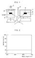
- Fig. 1 is a schematic diagram showing the principle of the present invention.
- a Color Comparison Condition is set under which an observer, such as a designer observing a color CRT monitor 1, can simultaneously visually observe the non-luminous object color B under an observatory condition of the non-luminous object surface color, which is specified in Japanese Industrial Standard JIS Z8723. If, under this Color Comparison Condition, a light-source color A, displayed on the color CRT monitor 1, and the non-luminous object color B are visually perceived as matched with each other by the observer, the light-source color data of the light source color A can be accurately transformed to the non-luminous object color data of a non-luminous object color B', which is equivalent to the non-luminous object color B.
- an observer such as a designer observing a color CRT monitor 1
- an observatory condition of the non-luminous object surface color which is specified in Japanese Industrial Standard JIS Z8723.
- reference numeral 2 designates an illuminating light source
- numeral 3 is the achromatic surroundings of the visual field of the non-luminous object color B
- numeral 4 or 4A is a color chip or the non-luminous object color B
- the numeral 5 is the viewing point of the observer.
- Numeral 6 designates a toning region on the color CRT monitor 1, which is the same size as that of the color chip 4 or 4A.
- Numeral 7 designates the achromatic surroundings on the color CRT monitor 1, which may have an arbitrary luminance so long as it is perceived as an achromatic light-source color.
- Numeral 8 designates a glare shield for shielding the color CRT monitor 1 from the illumination of the light source 2.
- the standard source C 2 as the illuminating light source, and mat paper 3 of N6.5 are set under the Color Comparision Condition shown in Fig. 1.
- the brightness of the achromatic surrounding 7 is adjusted so that it is equally perceived with that of the mat paper 3 of N6.5, which is illuminated with the standard source C 2, when observed from the view point 5.
- a toning region 6 is set within the achromatic surrounding 7 which can tone an arbitrary light-source color.
- each spectral reflectance factors R G ( ⁇ ) is known, color matching with the light-source colors in the toning region 6 is performed by the human eye.
- the light-source colors are displayed one after another in the toning region 6 of the color CRT monitor 1 to normalize the visual lightness scale so that the spectral distribution I G ( ⁇ ) of the light-source color (grey) is obtained. Therefore, the light-source color (grey) is produced by emitting all three phosphors (red (R), green (G) and blue (B)) of the color CRT monitor.
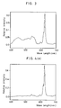
- Fig. 2 is a graph presenting the spectral reflectance factor of the achromatic color chip 4A (N5).
- Fig. 3 is a graph presenting the spectral distribution of the light-source color (grey) perceived as matched with the achromatic color chip 4A (N5) in the normalized visual lightness scale.
- an arbitrary light-source color A displayed in the toning region 6 on the color CRT monitor 1.
- the spectral distribution I C ( ⁇ ) of the light-source color A is determined either by a direct measurement using a spectroradiometer or by the following formula. In the latter determination, measurements of the red, green and blue phosphor light intensities for each input signal are made in advance by individually switching on the three electron guns of the color CRT monitor.
- I C ( ⁇ ) f1(R C ) i R ( ⁇ ) + f2(G C ) i G ( ⁇ ) + f3(B C ) i B ( ⁇ ), wherein: R C , G C and B C are the RGB video drive signals of the color monitor; i R ( ⁇ ), i G ( ⁇ ) and i B ( ⁇ ) are the respective spectral distributions when red, green and blue phosphors of the color CRT monitor radiate by themselves with their maximum luminances; and f1, f2 and f3 are the functions (or the gamma correction functions) for transforming the RGB video drive signals of the color CRT monitor to values corresponding to the phosphor-light-intensity outputs.
- the spectral distribution I C ( ⁇ ) of the light-source color A the spectral distribution I G ( ⁇ ) of the light-source color (grey) and the spectral reflectance factor R G ( ⁇ ) of the achromatic color chip (N5) are determined.
- the spectral reflectance factor R C ( ⁇ ) of a non-luminous object color B' which is perceived as matched with the light-source color A under the Color Comparision Condition, is determined from the spectral distribution I C ( ⁇ ) of the light-source color A:
- R C ( ⁇ ) [I C ( ⁇ )/I G ( ⁇ )] x R G ( ⁇ ) (1).
- the Munsell color standard chips 4 e.g., 5R5/14, 5YR5/12 and 5PB5/12
- the non-luminous object colors B which are perceived as matched with the aforementioned light-source color A under the aforementioned Color Comparison Condition
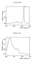
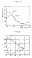
- Fig. 4(A) is a graph presenting the spectral distribution of the light-source color A which is perceived as matched with the Munsell colors standard chip 5R5/14.
- Fig. 4(B) is a graph presenting the spectral distribution of the light-source color A which is perceived as matched with the Munsell color standard chip 5YR5/12.
- Fig. 4(C) is a graph presenting the spectral distribution of the light-source colors A which are perceived as matched with the Munsell color standard chip 5PB5/12.
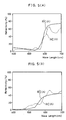
- Fig. 5(A) is a graph presenting that spectral reflectance factor R C ( ⁇ ) of the non-luminous object color B' (which is equivalent to the Munsell color standard chip 5R5/14,) which is determined from formula (1).
- Fig. 5(B) is a graph presenting the spectral reflectance factor R C ( ⁇ ) of the non-luminous object color B'(which is equivalent to the Munsell color standard chip 5YR5/12) which is determined from formula (1).
- Fig. 5(C) is a graph presenting the spectral reflectance factor R C ( ⁇ ) of the non-luminous object color B'(which is equivalent to the Munsell color standard chip 5PB5/12) which is determined from formula (1).
- the measured spectral reflectance factor R C '( ⁇ ) of the Munsell color standard chip 4A is also presented for comparison.
- the CIE tristimulus values X, Y and Z of the non-luminous object color B', having the spectral reflectance factor R C ( ⁇ ) determined from formula (1) can be calculated by a normal method using the following formula (2):
- the CIE tristimulus values X', Y' and Z' of the non-luminous object color B can be calculated from the following formula (3):
- Letter L( ⁇ ) designates the spectral distribution of the illuminating light source 2.
- Letters x( ⁇ ), y( ⁇ ) and z( ⁇ ) designate the color matching functions based on the CIE 1931 standard colorimetric system (or the CIE 1964 supplementary standard colorimetric system).
- Letter K is determined from the following formula (5):
- the light-source color A which is visually perceived as matched with the color standard chip 4 (having the known CIE tristimulus values X, Y and Z for the specified observing condition of the non-luminous object color B) under the set Color Comparison Condition.
- the RGB video drive signals of the light-source color A are designated at R C , G C and B C . With these designations, however, the color standard chip 4 selected here should have a color in which any of the signals R C , G C and B C is not zero in value.
- undetermined coefficients k R , k G and k B are determined by the following formula (6) using the above-specified CIE tristimulus values X, Y and Z of the non-luminous object color B and the above-specified RGB video drive signals R C , G C and B C of the light-source color A.
- the coefficients k R , k G and k B thus determined, the mutual transformations between the RGB video drive signals and the non-luminous object CIE tristimulus values are accomplished under the above-specified Color Comparision Condition:
- x R , y R and z R are the chromaticity coordinates of the red phosphor light of the color CRT monitor; x G , y g and z G are the chromaticity coordinates of the green phosphor light of the color CRT monitor; x B , y B and z B are the chromaticity coordinates of the blue phosphor light of the color CRT monitor; R C , G C and B C are the RGB video drive signals of the color CRT monitor; and f1, f2 and f3 are the functions (or the gamma correction functions) for transforming the RGB video drive signals of the color CRT monitor to values corresponding to the phosphor-light-intensity outputs.
- the undetermined coefficients k R , k G and k B are determined by substituting into formula (12) both the R0, and G0 and B0, which are determined by substituting the RGB video drive signals R C , G C and B C of the light-source color A into the formulas (8), (9) and (10), and the CIE tristimulus values X, Y and Z of the non-luminous object color B.
- the embodiment to be described is directed to the case in which the color CRT monitor is exemplified by the color graphic design system SDS-380 of Shima Seiki Seisakusho (KK) (CRT: C-6919JG of Mitsubishi Denki KK using 256 steps of RGB video drive signals.)
- KK Shima Seiki Seisakusho
- the matrix M expressed with the chromaticity coordinates of the red (R), green (G) and blue (B) phosphor lights takes the form of the following formula:
- Fig. 7 is a general perspective view of the first embodiment of the color comparator according to the present invention, and 11 represents the computer color graphic (CG) system.
- a color CRT monitor hood 13 is provided on the front part of color CRT monitor 12 of CG 11, and an illuminating light-source 16 such as the standard C light-source is furnished on lower front portion of the color CRT monitor 12.
- a shielding plate 17 is provided between the color CRT monitor screen 14 and the illuminating light source 16 so that the light from said illuminating light source 16 may not enter color CRT monitor screen 14.
- the specimen 18 such as color specimen, sample, color chip, etc. is placed on the table 19 under the illuminating light source 16 to give adequate light on the specimen 18.
- the changes of color due to isochromatic condition can be avoided.
- color CRT monitor hood 13 furnished on color CRT monitor 12 the reflection of the external light is prevented, and the light from the illumination light source 16 can also be blocked by the shielding plate 17 mounted between them. This makes it possible to see up the Color comparison Condition to compare the color of the light-source 15 in the toning region on the color CRT monitor screen 14 and the non-luminous object color.
- Fig. 8 is the second embodiment of the color comparator.
- a color CRT monitor hood 13 is provided on the front portion of color CRT monitor 12 of CG 11.
- an illuminating light-source 16 is furnished on the side of the color CRT monitor 12.
- a shielding plate 17 is provided between the lateral portion of color CRT monitor 12 and the illuminating light source 16 so that the light from said illuminating light source 16 may not enter the color CRT monitor screen 14.
- the specimen 18 to be observed is placed on the side of color CRT monitor unit 12, and the non-luminous object color of the specimen 18 lightened with adequate illuminating light source 16 and the light-source color 15 on color CRT monitor screen 14 can be compared. This makes it possible to provide the adequate condition to compare the color in the way similar to the example of Fig. 7 and to observe and compare the light-source color and the non-luminous object color on the same level.
Landscapes
- Physics & Mathematics (AREA)
- Spectroscopy & Molecular Physics (AREA)
- General Physics & Mathematics (AREA)
- Engineering & Computer Science (AREA)
- Mathematical Physics (AREA)
- Theoretical Computer Science (AREA)
- Controls And Circuits For Display Device (AREA)
- Spectrometry And Color Measurement (AREA)
Claims (8)
- Verfahren zur Umwandlung einer Lichtquellenfarbe (A) auf einem Kadodenstrahlröhren (CRT)-Farbmonitor (1) in einen Spektralreflexionsfaktor, wobei das Verfahren die Schritte umfaßt:
Einrichten einer Farbvergleichsbedingung, bei der eine Lichtquellenfarbe (A), umgeben mit einer achromatischen Lichtquellenfarbe (7), auf dem (CRT)-Farbmonitor (1) und eine Farbe (B) eines nichtleuchtenden Objektes, umgeben mit einer achromatischen Umgebung, in einem Sichtfeld (3) gleichzeitig beobachtet werden können;
bestimmen des Spektralreflexionsfaktors Rc(λ) eines Objektes, welches bei der Farbvergleichsbedingung als mit einer willkürlichen Lichtquellenfarbe auf dem CRT-Farbmonitor (1) angepaßt wahrgenommen werden kann, auf der Basis der Spektralverteilung Ic(λ) der willkürlichen Lichtquellenfarbe, die auf dem CRT-Farbmonitor (1) bei der Farbvergleichsbedingung dargestellt ist, unter Verwendung der folgenden Formel;

worin:
IG(λ) ist die Spektralverteilung der Lichtquellenfarbe (A), welche bei der Farbvergleichsbedingung als mit einem Farbchip (4), der einen Spektralreflexionsfaktor RG(λ) aufweist, angepaßt wahrgenommen wird und welche durch emittieren aller drei Leuchtschirmsubstanzen (rot (R), grün (G) und blau (B)) des CRT-Farbmonitors (1) erzeugt wird. - Verfahren zur wechselseitigen Umwandlung von roten, grünen und blauen (RGB)-Videotriebsignalen eines CRT-Farbmonitors (1) und von CIE-Tristimulus-Werten einer Farbe (B) eines nichtleuchtenden Objektes, wobei das Verfahren die Schritte umfaßt:
Einrichtern einer Farbvergleichsbedingung, bei der eine Lichtquellenfarbe (A), umgeben mit einer achromatischen Lichtquellenfarbe (7), auf den (CRT)-Farbmonitor (1) und die Farbe (B) eines nichtleuchtenden Objektes, umgeben mit einer achromatischen Umgebung, in einem Sichtfeld (3) gleichzeitig beobachtet werden können;
Bestimmung der unbestimmten Koeffizienten KR, KG und KB sowohl aus den bekannten CIE-Tristimulus-Werten X, Y und Z einer Farbe (B) eines nichtleuchtenden Objektes und den RGB-Videotriebsignalen RC, GC und BC einer Lichtquellenfarbe (A), welche bei der Farbvergleichsbedingung vom menschlichen Auge als mit der Farbe (B) des nichtleuchtenden Objektes angepaßt wahrgenommen wird und welche durch emittieren aller drei Leuchtschirmsubstanzen (rot (R), grün (G) und blau (B)) des CRT-Farbmonitors (1) erzeugt wird, bei Verwendung der folgenden Formel: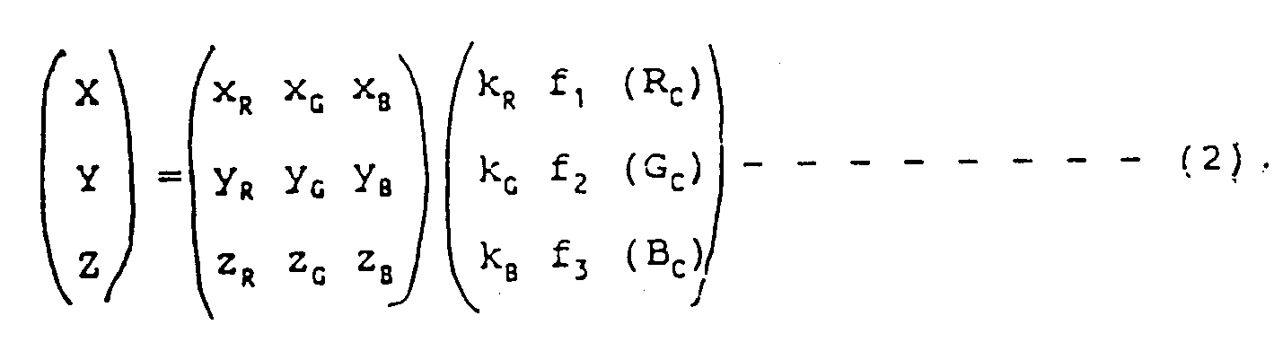
XR, YR und ZR die Farbtonbeiwerte des roten Leuchtschirmsubstanzlichtes des CRT-Farbmonitor (1) sind;
XG, YG und ZG die Farbtonbeiwerte des grünen Leuchtschirmsubstanzlichtes des CRT-Farbmonitors (1) sind;
XB, YB und ZB die Farbtonbeiwerte des blauen Leuchtschirmsubstanzlichtes des CRT-Farbmonitors (1) sind;
RC, GC und BC die RGB-Videotriebsignale des CRT-Farbmonitors (1) sind; und
f₁, f₂ und f₃ die Funktionen oder die Gamma-Korrekturfunktionen für die Umwandlung der RGB-Videotriebsignale des CRT-Farbmonitors (1) zu Werten entsprechend den Leuchtschirmsubstanz-Lichtintensitätsausgängen sind; und
die wechselseitige Umwandlung einer willkürlichen Lichtquellenfarbe auf dem CRT-Farbmonitor (1) und jener Farbe (B) eines nichtleuchtenden Objektes, welche bei der Farbvergleichsbedingung als mit der willkürlichen Lichtquellenfarbe angepaßt wahrgenommen wird, durch Verwendung der bestimmten Koeffizienten KR, KG und KB in der Formel. - Umwandlungsverfahren nach Anspruch 1 oder 2, bei dem die Umgebungslichtquellenfarbe (7) auf dem CRT-Farbmonitor (1) eine willkürlich Helligkeit besitzen kann, so lange sie als eine achromatische Farbe wahrgenommen wird.
- Umwandlungsverfahren nach Anspruch 1 oder 2, bei dem die Farbe (B) des nichtleuchtenden Objektes und die achromatische Umgebung mit einem Standardlicht bei der Farbvergleichsbedingung beleuchtet werden.
- Umwandlungsverfahren nach Anspruch 1 oder 2, bei dem der CRT-Farbmonitor (1) nicht mit einem Standardlicht bei der Farbvergleichsbedingung beleuchtet wird.
- Umwandlungsverfahren nach Anspruch 1 oder 2, bei dem die achromatische Umgebung (3) der Farbe (B) des nichtleuchtenden Objektes von einem Mattpapier oder dgl. entsprechend JIS Z8723, welcher das Vergleichsverfahren für eine Oberflächenfarbe spezifiziert, erzeugt wird.
- Vergleichsverfahren nach Anspruch 2, bei dem die Farbe (B) des nichtleuchtenden Objektes, wie z.B. einem Farbchip (4), in der achromatischen Umgebung des Sichtfeldes (3), verwendet für die Bestimmung der Koeffizienten KR, KG und KB, als mit einer Lichtquellenfarbe (A), welche auf dem CRT-Farbmonitor (1) dargestellt werden kann, bei der Farbvergleichsbedingung als angepaßt wahrgenommen wird, und die Lichtquellenfarbe (A) durch emittieren aller drei Leuchtschirmsubstanzen (rot (R), grün (G) und blau (B)) des CRT-Farbmonitors erzeugt wird.
- Farbvergleichersystem zum gleichzeitigen beobachten und vergleichen einer nichtleuchtenden Objektfarbe (18) eines Musters, umgeben mit einer achromatischen Umgebung in einem Sichtfeld und der Lichtquellenfarbe, umgeben mit einer achromatischen Lichtquellenfarbe, dargestellt auf einem Bildschirm eines CRT-Farbmonitors (12), umfassend eine CRT-Farbmonitoreinheit (12) zum Darstellen der Lichtquellenfarbe, eine leuchtende Lichtquelle (16) zum beleuchten des nahe der Monitoreinheit angeordneten Musters, und eine Abschirmplatte (17), die zwischen der leuchtenden Lichtquelle und der Monitoreinheit angebracht ist.
Applications Claiming Priority (6)
| Application Number | Priority Date | Filing Date | Title |
|---|---|---|---|
| JP172938/88 | 1988-07-12 | ||
| JP63172937A JPH0670740B2 (ja) | 1988-07-12 | 1988-07-12 | Crtカラーディスプレイの光源色から分光立体角反射率への変換法 |
| JP17293888A JPH0678947B2 (ja) | 1988-07-12 | 1988-07-12 | Crtカラーディスプレイの発光制御信号と物体色cie三刺激値の相互変換法 |
| JP172937/88 | 1988-07-12 | ||
| JP131253/88 | 1988-10-06 | ||
| JP13125388U JPH0643705Y2 (ja) | 1988-10-06 | 1988-10-06 | 物体色と光源色の色比較装置 |
Publications (3)
| Publication Number | Publication Date |
|---|---|
| EP0351188A2 EP0351188A2 (de) | 1990-01-17 |
| EP0351188A3 EP0351188A3 (en) | 1990-08-22 |
| EP0351188B1 true EP0351188B1 (de) | 1993-10-06 |
Family
ID=27316274
Family Applications (1)
| Application Number | Title | Priority Date | Filing Date |
|---|---|---|---|
| EP89307028A Expired - Lifetime EP0351188B1 (de) | 1988-07-12 | 1989-07-11 | Verfahren zur Umwandlung von Farbendaten einer Lichtquelle und Farbendaten eines nichtleuchtenden Objektes |
Country Status (4)
| Country | Link |
|---|---|
| US (1) | US5033857A (de) |
| EP (1) | EP0351188B1 (de) |
| CA (1) | CA1319990C (de) |
| DE (1) | DE68909701T2 (de) |
Families Citing this family (13)
| Publication number | Priority date | Publication date | Assignee | Title |
|---|---|---|---|---|
| FI80792C (fi) * | 1988-05-06 | 1990-07-10 | Teknillinen Korkeakoulu | Betraktningsapparatur avsedd foer pao kolorimetrisk faergbestaemning baserad reproduktion eller avdragning. |
| ES2059096T3 (es) * | 1990-03-02 | 1994-11-01 | Ciba Geigy Ag | Procedimiento para la determinacion de recetas de tintura e impresion segun una muestra de color. |
| WO1994001755A1 (en) * | 1992-07-02 | 1994-01-20 | Michael Fredrick Feasey | Method and calibration device for calibrating computer monitors used in the printing and textile industries |
| DE69424321T2 (de) * | 1993-08-06 | 2000-10-19 | Toyota Jidosha K.K., Toyota | Verfahren zur Selektion der Farbe eines Lackes |
| US5670985A (en) * | 1994-05-09 | 1997-09-23 | Apple Computer, Inc. | System and method for adjusting the output of an output device to compensate for ambient illumination |
| DE19755655A1 (de) * | 1997-12-15 | 1999-06-17 | Logo Kommunikations Und Druckt | Verfahren zur farbmetrischen Charakterisierung eines selbstleuchtenden Abbildungssystems |
| JP2000121440A (ja) * | 1998-10-15 | 2000-04-28 | Keyence Corp | 色識別装置 |
| US6577395B1 (en) * | 1999-08-19 | 2003-06-10 | Rochester Institute Of Technology | Method for measuring a lighting condition and an apparatus thereof |
| US7230737B1 (en) * | 1999-09-17 | 2007-06-12 | Canon Kabushiki Kaisha | Image processing method and apparatus |
| DE60332155D1 (de) * | 2002-12-12 | 2010-05-27 | Koninkl Philips Electronics Nv | Transformationsstrukturen zur annäherung von farbabstimmungsfunktionen |
| KR100916484B1 (ko) * | 2007-08-14 | 2009-09-08 | 삼성전기주식회사 | 자동 화이트 밸런스 방법 |
| CN103983359B (zh) * | 2014-06-03 | 2015-12-02 | 北京印刷学院 | 一种分类观察者颜色匹配函数的方法 |
| JP6439531B2 (ja) * | 2015-03-24 | 2018-12-19 | 富士ゼロックス株式会社 | 色処理装置、色処理システムおよびプログラム |
Family Cites Families (4)
| Publication number | Priority date | Publication date | Assignee | Title |
|---|---|---|---|---|
| US4670780A (en) * | 1985-05-28 | 1987-06-02 | Tektronix, Inc. | Method of matching hardcopy colors to video display colors in which unreachable video display colors are converted into reachable hardcopy colors in a mixture-single-white (MSW) color space |
| US4742387A (en) * | 1986-03-17 | 1988-05-03 | Sony Corporation | Method and apparatus for automatically establishing a color balance of a color television monitor including an ambient light sensing and data compensating function |
| US4799104A (en) * | 1986-12-19 | 1989-01-17 | Olympus Optical Co., Ltd. | Video signal processor for endoscope |
| US4875032A (en) * | 1987-10-26 | 1989-10-17 | Mcmanus Paul A | Method and apparatus for processing colorimetric parameters of a color sample |
-
1989
- 1989-07-11 EP EP89307028A patent/EP0351188B1/de not_active Expired - Lifetime
- 1989-07-11 US US07/378,664 patent/US5033857A/en not_active Expired - Fee Related
- 1989-07-11 DE DE89307028T patent/DE68909701T2/de not_active Expired - Fee Related
- 1989-07-12 CA CA000605415A patent/CA1319990C/en not_active Expired - Fee Related
Also Published As
| Publication number | Publication date |
|---|---|
| DE68909701D1 (de) | 1993-11-11 |
| EP0351188A2 (de) | 1990-01-17 |
| CA1319990C (en) | 1993-07-06 |
| EP0351188A3 (en) | 1990-08-22 |
| DE68909701T2 (de) | 1994-02-03 |
| US5033857A (en) | 1991-07-23 |
Similar Documents
| Publication | Publication Date | Title |
|---|---|---|
| EP0351188B1 (de) | Verfahren zur Umwandlung von Farbendaten einer Lichtquelle und Farbendaten eines nichtleuchtenden Objektes | |
| CA2091155C (en) | Method and apparatus for reproducing blended colorants on an electronic display | |
| EP1759631B1 (de) | Fluorezentlicht Bilddarstellungsverfahren und Gerät dafür | |
| US5798943A (en) | Apparatus and process for a digital swatchbook | |
| JP3300710B2 (ja) | カラー印刷システム較正方法 | |
| Luo et al. | A chromatic adaptation transform and a colour inconstancy index | |
| EP0531891A2 (de) | Verfahren besonders geeignet zur Anwendung in einer Druckvorschaufunktion zur Anpassung der Kolorimetrie der Kathodenstrahlröhren an den Bedingungen der Umgebungsbeleuchtung | |
| US20020135828A1 (en) | Chromaticity conversion device and chromaticity conversion method | |
| JP3635673B2 (ja) | 画像処理方法および画像処理装置 | |
| JP3740229B2 (ja) | カラー表示装置における色温度決め方法 | |
| US6313823B1 (en) | System and method for measuring the color output of a computer monitor | |
| JPH0678947B2 (ja) | Crtカラーディスプレイの発光制御信号と物体色cie三刺激値の相互変換法 | |
| JP2008129162A (ja) | 映像変換処理方法および映像変換システム | |
| MacDonald et al. | Factors affecting the appearance of coloured images on a video display monitor | |
| Tonnquist et al. | Application of colour video displays to colour research | |
| Cheng | 82‐4: Color characterization of virtual reality devices using professional‐and consumer‐grade instruments | |
| JP3318912B1 (ja) | 三刺激値直読測色装置 | |
| SUGIYAMA | Guidelines for Viewing Conditions of Printed Matter Using LED Lightings for Color Evaluation | |
| JPH0643705Y2 (ja) | 物体色と光源色の色比較装置 | |
| KR100335619B1 (ko) | 칼라표시장치에있어서색온도결정방법 | |
| Herbert et al. | Absolute and relative colorimetric evaluation for precise color on screen | |
| Neri | A simple calibration procedure for color CRT displays | |
| Bala | What is the Chrominance of “Gray”? | |
| JPH0777957A (ja) | 画像出力装置 | |
| JPH0223396A (ja) | Crtカラーディスプレイの光源色から分光立体角反射率への変換法 |
Legal Events
| Date | Code | Title | Description |
|---|---|---|---|
| PUAI | Public reference made under article 153(3) epc to a published international application that has entered the european phase |
Free format text: ORIGINAL CODE: 0009012 |
|
| AK | Designated contracting states |
Kind code of ref document: A2 Designated state(s): DE FR GB IT |
|
| PUAL | Search report despatched |
Free format text: ORIGINAL CODE: 0009013 |
|
| AK | Designated contracting states |
Kind code of ref document: A3 Designated state(s): DE FR GB IT |
|
| 17P | Request for examination filed |
Effective date: 19901231 |
|
| 17Q | First examination report despatched |
Effective date: 19920518 |
|
| GRAA | (expected) grant |
Free format text: ORIGINAL CODE: 0009210 |
|
| AK | Designated contracting states |
Kind code of ref document: B1 Designated state(s): DE FR GB IT |
|
| ET | Fr: translation filed | ||
| REF | Corresponds to: |
Ref document number: 68909701 Country of ref document: DE Date of ref document: 19931111 |
|
| ITF | It: translation for a ep patent filed | ||
| ITTA | It: last paid annual fee | ||
| PLBE | No opposition filed within time limit |
Free format text: ORIGINAL CODE: 0009261 |
|
| STAA | Information on the status of an ep patent application or granted ep patent |
Free format text: STATUS: NO OPPOSITION FILED WITHIN TIME LIMIT |
|
| 26N | No opposition filed | ||
| PGFP | Annual fee paid to national office [announced via postgrant information from national office to epo] |
Ref country code: GB Payment date: 20010627 Year of fee payment: 13 |
|
| PGFP | Annual fee paid to national office [announced via postgrant information from national office to epo] |
Ref country code: FR Payment date: 20010629 Year of fee payment: 13 |
|
| PGFP | Annual fee paid to national office [announced via postgrant information from national office to epo] |
Ref country code: DE Payment date: 20010727 Year of fee payment: 13 |
|
| REG | Reference to a national code |
Ref country code: GB Ref legal event code: IF02 |
|
| PG25 | Lapsed in a contracting state [announced via postgrant information from national office to epo] |
Ref country code: GB Free format text: LAPSE BECAUSE OF NON-PAYMENT OF DUE FEES Effective date: 20020711 |
|
| PG25 | Lapsed in a contracting state [announced via postgrant information from national office to epo] |
Ref country code: DE Free format text: LAPSE BECAUSE OF NON-PAYMENT OF DUE FEES Effective date: 20030201 |
|
| GBPC | Gb: european patent ceased through non-payment of renewal fee |
Effective date: 20020711 |
|
| PG25 | Lapsed in a contracting state [announced via postgrant information from national office to epo] |
Ref country code: FR Free format text: LAPSE BECAUSE OF NON-PAYMENT OF DUE FEES Effective date: 20030331 |
|
| REG | Reference to a national code |
Ref country code: FR Ref legal event code: ST |
|
| PG25 | Lapsed in a contracting state [announced via postgrant information from national office to epo] |
Ref country code: IT Free format text: LAPSE BECAUSE OF NON-PAYMENT OF DUE FEES;WARNING: LAPSES OF ITALIAN PATENTS WITH EFFECTIVE DATE BEFORE 2007 MAY HAVE OCCURRED AT ANY TIME BEFORE 2007. THE CORRECT EFFECTIVE DATE MAY BE DIFFERENT FROM THE ONE RECORDED. Effective date: 20050711 |