EP0351228A2 - Vorrichtung zur Spitzendatenermittlung und Vorrichtung zur Berechnung einer rekursiven Rotativbewegungsformel - Google Patents
Vorrichtung zur Spitzendatenermittlung und Vorrichtung zur Berechnung einer rekursiven Rotativbewegungsformel Download PDFInfo
- Publication number
- EP0351228A2 EP0351228A2 EP89307147A EP89307147A EP0351228A2 EP 0351228 A2 EP0351228 A2 EP 0351228A2 EP 89307147 A EP89307147 A EP 89307147A EP 89307147 A EP89307147 A EP 89307147A EP 0351228 A2 EP0351228 A2 EP 0351228A2
- Authority
- EP
- European Patent Office
- Prior art keywords
- data
- coordinates
- coordinate data
- adder
- coordinate
- Prior art date
- Legal status (The legal status is an assumption and is not a legal conclusion. Google has not performed a legal analysis and makes no representation as to the accuracy of the status listed.)
- Withdrawn
Links
Images


Classifications
-
- G—PHYSICS
- G06—COMPUTING OR CALCULATING; COUNTING
- G06F—ELECTRIC DIGITAL DATA PROCESSING
- G06F7/00—Methods or arrangements for processing data by operating upon the order or content of the data handled
- G06F7/22—Arrangements for sorting or merging computer data on continuous record carriers, e.g. tape, drum, disc
- G06F7/24—Sorting, i.e. extracting data from one or more carriers, rearranging the data in numerical or other ordered sequence, and rerecording the sorted data on the original carrier or on a different carrier or set of carriers sorting methods in general
-
- G—PHYSICS
- G06—COMPUTING OR CALCULATING; COUNTING
- G06F—ELECTRIC DIGITAL DATA PROCESSING
- G06F7/00—Methods or arrangements for processing data by operating upon the order or content of the data handled
- G06F7/38—Methods or arrangements for performing computations using exclusively denominational number representation, e.g. using binary, ternary, decimal representation
- G06F7/48—Methods or arrangements for performing computations using exclusively denominational number representation, e.g. using binary, ternary, decimal representation using non-contact-making devices, e.g. tube, solid state device; using unspecified devices
- G06F7/544—Methods or arrangements for performing computations using exclusively denominational number representation, e.g. using binary, ternary, decimal representation using non-contact-making devices, e.g. tube, solid state device; using unspecified devices for evaluating functions by calculation
- G06F7/548—Trigonometric functions; Co-ordinate transformations
-
- G—PHYSICS
- G06—COMPUTING OR CALCULATING; COUNTING
- G06V—IMAGE OR VIDEO RECOGNITION OR UNDERSTANDING
- G06V10/00—Arrangements for image or video recognition or understanding
- G06V10/40—Extraction of image or video features
- G06V10/48—Extraction of image or video features by mapping characteristic values of the pattern into a parameter space, e.g. Hough transformation
Definitions
- This invention relates to a peak data extracting device and a rotary motion recurrence formula computing device which are used in picture processing devices using, e.g., Hough transforms.
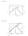
- Fig. 1(a) and (b) are views explaining recognition of a road by means of a picture.
- Fig. 1(a) shows a picture of a road taken by a camera.
- Fig. 1(b) is a view in which the picture elements in Fig. 1(a) having higher brightness (or higher brightness change ratios) are shown in black points.
- a road 3 is extended at infinity toward a horizontal line 2.
- Shoulder lines 4 are on both sides of the road 3.
- a center line 5 is at the center of the road 5.
- the shoulder lines 4 and the center line 5, of the road 3 have higher brightnesses than the other parts of the road 3 and are shown in continuous dots 4′, 5′ as shown in Fig. 1(b).
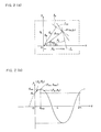
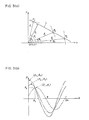
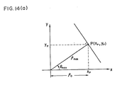
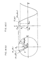
- Hough transform As a method for giving the approximate straight lines L, the method called Hough transform is conventionally known (e.g., Specification of U.S. Patent No. 3069654). Assuming that a point P (x p ,y p ) to be processed is present on an original picture drawn by the x-y coordinate system as shown in Fig. 2(a), an infinite number of straight lines l (l a , l b , ...) can be drawn. Straight lines passing through the origin 0 (0,0) and ortogonal to the respective straight lines l a , l b ,... can be also depicted.
- the length ⁇ max between the origin O (0,0) and the point to be processed P (x p ,y p ) is the longest of the straight lines passing through the point to be processed P (x p ,y p ).
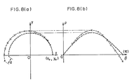
- the Hough transform of Fig. 2 (a) and (b) will be applied to three points P1 ⁇ P3 on a straight line L shown in Fig. 3(a).
- the sine curve (Hough curve) in the dot line in Fig. 3(b) is given with respect to the point P1.
- the sine curve (Hough curve) with respect to the point P2 the one dot line in Fig. 3(b), and that with respect to the point P3 is the two dot line in Fig. 3(b).
- 3(b) correspond to the lengths ⁇ 1 ⁇ 3 between the origin O (0,0) and the respective points P1, P2 and P3 in Fig. 3(a), and the angles ⁇ 1 ⁇ ⁇ 3 the respective straight lines passing through the origin O form to the x axis.
- the peak P2 has a lower peak value than the peaks P3 and P4, but in the picture processing the peak P2 is a peak to be detected desirably next to the peak P1. Unless the peak P2 can be detected, the picture processing becomes very difficult as will be explained below.
- a first object of this invention is to provide a peak data extracting device which can exact peak data with noise components removed, by a simple system and at high speed.
- a point P i+1 (x i+1 , y i+1 ) can be computed, based on a point P i (x i , y i ) using Formula 5, 6 which is derived as follows. That is, in a rectangular x-y coordinate system, the point P i+1 (x i+1 , y i+1 ) to which the point P i (x i , y i ) spaced by ⁇ from the origin O(0,0) is rotated by ⁇ (rad) with the origin centered is given as follows.
- the rotary motion becomes spiral, and the recurrence formula 9, 10 is not practically used.
- the following rotary motion recurrence formula x i+1 x i - ⁇ y i (11)
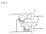
- the recurrence formula 11, 12 is computed by the hardware exemplified in Fig. 7.
- the formula 11, 12 enables a rotary motion to be approximated by comparatively simple hardware.
- the hardware involving such errors cannot be used for, e.g., Hough transform. That is, in a case where a relative error with respect to a diameter of a circle is about ⁇ 0.4% (the quantitized error for the case, for example, where ⁇ (a distance from the origin to a line segment) is divided into 128 sections in Hough transform is within ⁇ 0.4%), no practical troubles take place, but for such relative error, the rotation angle ⁇ has to be made very small.
- a second object of this invention is to provide a device for computing a rotary motion recurrence formula whose hardware structure is simple, which is suitable for high speed computation and allows large rotation angles to be set while making errors minimum.
- the peak data extracting device of this invention extracts peak data from data corresponding to respective coordinates of at least a two dimensional coordinate system and comprises comparing means for comparing data corresponding to required coordinates in the coordinate system with data of coordinates adjacent to the required coordinates; and outputting means for outputting the coordinate values of the required coordinates and data corresponding to the required coordinates when the comparing means judges the data of the required coordinates to be peak data.
- the peak extracting device further comprises sorting hardware (a sorting unit) for sorting extracted peak data.
- the peak data extracting device this invention relates to may comprise computing means for executing Hough transform on respective plural points to be processed in a first two dimensional coordinate system to give Hough curves in a second two dimensional coordinate system, and outputting data of a histogram of intersections of the Hough curves in correspondence with the coordinates of the intersections; and extracting means for comparing data corresponding to coordinates adjacent to required coordinates in the second coordinate system, and outputting the coordinate values of the required coordinates and data corresponding thereto when the data of the required coordinates is judged to be peak data.
- the peak extracting device may further comprise sorting hardware(a sorting unit) for sorting extracted peak data.
- Fig. 10 shows the basic structure and the function of the peak data extracting device according to an embodiment of this invention.
- the device according to this embodiment comprises a DDA (data differential analysis) computing unit 18, an eight neighboring peak filter 19, and a sorting unit 20 which are serially connected to each other.
- DDA data differential analysis
- the DDA computing unit 18 gives Hough curves based on points to be processed on an original picture to derive an occurrence of the intersecting points of the Hough curves.
- the maximum occurrence of the points of intersection is "9", and the occurrence decreases to "8" "7", "6" ..
- the eight neighboring peak filter 19 extracts the peak data (circled in Fig. 10(b)). Thus, six peak data are extracted with the noise components removed.
- the sorting unit 20 sorts the six peak data.
- Fig. 11 is a general block diagram of the picture processing device the peak data extracting device according to this embodiment is applied to.
- a camera 11 takes a picture of an object to be processed (e.g., a road, a high speed moving object, or the like) as an original picture.
- the picture signals are digitized by a signal inputting unit 12 to be supplied to an edge detecting unit 13.
- the edge detecting unit 13 extracts the edges of the picture signals to produce edged data having different brightnesses, e.g., 512x512 picture element signals (edged picture element signals) and supplies the same to a multivalued memory 14.
- the multivalued memory 14 stores the edged data for the respective picture elements.
- the edged data are supplied to a D/A converting unit 15 to be supplied to a CRT display 16 as analog signals.
- the edged data are displayed on the CRT display 16.
- the edged picture element signals are supplied to a pre-processing unit 17 to be processed.
- the pre-processed edged picture element signals are supplied to a DDA computing unit 18 through an initial value computing unit 40.
- the DDA computing unit 18 comprises DDA computing circuits 180 ⁇ 18 n-1 which are connected serially.
- a neighboring peak filter 19 and a sorting unit 20 are connected to the DDA computing unit 18 on the side of the output thereof for the neighboring peak filtering and the sorting (which will be described later).
- the above described circuit elements are connected to a CPU 22 through a VME bus 21 for the control of the signal processing operation and the synchronization of the signal processing timing.
- the pre-processing unit 17, the DDA computing unit 18, and the peak filter 19 are interconnected by a VME bus 23 for the control of the synchronization of transfer of the computation result of the DDA computing unit and that of brightness value data.
- Fig. 12 corresponds to the pre-processing unit 17, the initial value computing unit 40, the DDA computing unit 18 and the peak filter 19 (peak data extracting means) in Fig. 11.
- the pre-processing unit 17 is provided by a FIFO (first-in first-out) board 17′.
- the FIFO 17′ inputs as an address signal coordinate values (X p , Y p ) in KY plane of a point to be processed, and edged brightness value data D I as a data signal.
- the FIFO 17′ transforms the X-Y coordinates to x-y coordinates, sets one or a plurality of windows, and threshold processes at a required level to output the results sequentially FIFO.
- the initial value computing unit in Fig. 11 comprises two flip flops (F/F's) 41, 42 and an initial value computing circuit 43.
- the F/F 41 temporarily stores coordinate values (x p , y p ) of the coordinates of a point to be processed P.
- the F/F 42 temporarily stores brightness data of the point to be processed P.
- the initial value computing circuit 43 computes coordinates of an initial value in an ⁇ - ⁇ rectangular coordinate system, based on the coordinate values (x p , y p to thereby enable the computation of the rotary motion recurrence formula.
- Each DDA computing circuit 180 ⁇ 18 n-1 in Fig. 11 comprises, as shown in Fig. 12, three flip flops (F/Fs) 31, 32, 33.
- the respective F/Fs 31 temporarily store address signals a0 ⁇ ⁇ n-1 , ⁇ 0 ⁇ B n-1 .
- the respective F/Fs 32 store brightness value data D I .
- Each F/Fs 33 temporarily store histogram data D M0 ⁇ D M(n-1) read from respective RAMs 34 (RAM0 ⁇ RAM n-1 .
- Respective DDAs 37 (DDA0 ⁇ DDA n-1 ) compute a rotary motion recurrence formula which will be described later, every rotation by a rotation angle.
- the respective DDAs 37 are supplied with address signals ⁇ i , ⁇ i to output address signals ⁇ i+1 , ⁇ i+1 .
- Respective ADDs 35 (ADD0 ⁇ ADD n-1 ), adders, add the brightness value data D1 from the FIFO 17′ and the histogram data D MO ⁇ D M(n-1) .
- the outputs from the respective ADDs are temporarily stored in a buffer 36 and then supplied to the respective RAM0 ⁇ RAM n-1 .
- a timing controller 25 outputs timing pulses ⁇ s , ⁇ ⁇ a ⁇ ⁇ e to control the timing of the signal processing among these circuit elements and is connected to a command/status interface (1/F) not shown.
- Step 102 picture element signals for respective points to be processed on an original picture taken by the camera 11 are inputted through the signal inputting unit 12 (Step 102).
- the signals are edged by the edge detecting unit 13 (Step 104) to input the edged data to the pre-processing unit 17 (step 106).
- Steps 102 ⁇ 106 are repeated every time picture element signals are inputted, and their results (edged data) are sequentially supplied to the pre-processing unit 17 as digital data.
- the pre-processing unit 17 executes the required pre-processing (Step 108) to supply pre-processed data to the initial value computing unit 10 (Step 110).
- the pre-processing is repeated every time edged data is supplied to the pre-processing unit 17.
- Step 112 the rotary motion recurrence formula is computed in DDA computation to give a Hough curve.
- initial values are computed in Step 111.
- the computation by the DDA computing unit 18 continues until the DDA computation is completed on the ones of the picture elements on one original picture which have not been removed by the pre-processing unit 17 as out of a window or below a threshold (Step 114).
- the DDA computation is followed by the filtering by the peak filter 19 (Step 116) and the sorting by the sorting unit 20 (Step 118), both of which will be explained below.
- a final result is an approximate straight line of curves interconnecting the points to be processed on the original picture.
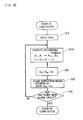
- Fig. 15 is a flow chart of the computing process.
- the data which have been pre-processed by the FIFO 17′ is inputted to give initial values ( ⁇ 0, ⁇ 0) for a computation of the rotary motion recurrence formula (Step 132).
- the ( ⁇ 0, ⁇ 0) are computed by the initial value computing unit 40 to be supplied as an address signal to the DDA computing unit 18.
- values of the sin ⁇ ′, cos ⁇ ′ are stored firstly in a ROM (not shown) for the computation of Formula 29 using adders and multipliers (not shown) with reference to these data.
- Formula 29 needs more computation times and is complicated, but Formula 29 needs the computation only once on one point to be processed (x p , y p ). This neither much increases the total computing time nor much enlarges the hardware.
- Step 140 This computation is repeated each rotation by the angle ⁇ until one round has been finished along a circle (Step 140).
- a Hough curve with respect at one point to be processed on an original picture is given, based on the thus stored values ⁇ 0, ⁇ 1, ⁇ 2, ⁇ 3, ..., and values (rotation angle ⁇ ) of ⁇ 0, ⁇ 1, ⁇ 2, ..., and also results weighted with brightness data (D M0 , D M1 , ... D M(n-1) ) are given.
- a plurality of Hough curves weighted with brightness data are given in the ⁇ - ⁇ coordinate system, and these Hough curves have points of intersection as in Fig. 3 (b).
- Step 132 of inputting data in Fig. 15 is executed by supplying a ready signal from the FIFO 17′ in Fig. 12 to the timing controller 25 and supplying a read strobing signal from the timing controller 25 to the FIFO 17′, then storing the coordinates (x p , y p ) of the point to be processed P by the F/F 41, and storing a brightness data D I of the point P by F/F 42.
- ⁇ s of the timing controller 25 In synchronization with a timing pulse ⁇ s of the timing controller 25.
- the (x p , y p ) are outputtted by F/F 41, and the initial values computing unit 40 gives initial values ( ⁇ 0, ⁇ 0) for the recurrence formula, based on the coordinate values (x p , y p ) of the point to be processed P.
- the computation of the recurrence formula in Step 134 is performed by supplying an output of the initial values computing circuit 43 from the F/F 17′ to the F/F 31 as address signals ⁇ 0, ⁇ 0, and supplying brightness data D I of the point to be processed from the F/F 42 to the F/F 32.
- the input of the address signals and the data to the F/Fs 31 and 32 are performed in synchronization with a timing pulse from the timing controller 25.
- Address signals ⁇ 0, ⁇ 0 from the F/F 31 are inputted to a first DDA0 in synchronization with a rise or fall of a timing pulse ⁇ a .
- Step 134 in Fig. 15 the processing of Step 134 in Fig. 15 is performed. That is, the computation of the recurrence formula in accordance with Formula 7 is executed, and a computation result (address signals ⁇ 1, ⁇ 1) is supplied to a next DDA1 (not shown).
- Recurrence Formula 27 basically neither includes computations of the trigonometric function and multiplications, nor needs to refer to a memory table (ROM). This makes the computation speedy and easy, and gives sufficient precision (little error) for the rotary motion.
- DDA0 comprises the same elements as DDA1 ⁇ DDA n-1 . Its specific structure and operation will be explained later.
- the address signal ⁇ 0 stored in the F/F 31 is supplied also to the RAM0 (34).
- the histogram data D MO is supplied from the F/F 33 to the ADD0.
- the ADD0 has been supplied by the F/F 32 with brightness data D I of the point to be processed (x p , y p ). Accordingly, in the ADD0, the rotation angle ⁇ 0 which has been stored in the RAM0, the histogram data D MO corresponding to the address ⁇ 0, the rotation angle ⁇ 0 of the point being processed (x p , y p ), and the brightness value data D I corresponding to the address ⁇ 0 are added (Step 136 in Fig. 15).
- Address signals ⁇ i+1 , ⁇ i+1 , a result of the computation, are supplied to the F/F 31 positioned before the DDA i+1 in the next DDA computation circuit 18 i+1 in synchronization with the finish of one cycle of processing.
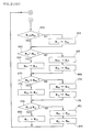
- Step 206 read of the histogram data D Mi is performed in Step 206.
- This read is performed by supplying the address signal ⁇ i from the F/F 31 to the RAM i to store the histogram data D Mi at the address of ⁇ i in the F/F 33 in Fig. 12.
- Step 208 the brightness data D I of the histogram data D Mi is added.
- Step 208 is executed by the ADD i in Fig. 12.
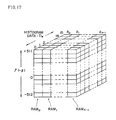
- Fig. 17 shows the concept of the histogram memory of the RAM 34 in Fig 12.
- Each address can store 16 bit histogram data (brightness value).
- the DDA i computes ⁇ i+1 , ⁇ i+1 corresponding to the rotation angle ⁇ i+1 based on the address signal ⁇ i , ⁇ i , using Recurrence Formula 27, the address signal ⁇ i is supplied to the RAM i , and the histogram data D M(i) is read and combined with the brightness data D I of a point to be processed. Then the histogram data (D Mi + D I ) is written at the address ⁇ i .
- the computation of Recurrence Formula 27 is performed in the pipeline system in which the address signals ⁇ i , ⁇ i are transferred sequentially.
- the brightness data D I stores the histogram data D Mi , which shortens the time required for one cycle of processing.
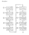
- This one cycle of processing is performed by the DDA computing circuits 180 ⁇ 18 n-1 simultaneously and parallelly. That is, as in Fig. 18(a), "data 1,none,, 2, none, none, 3, 4 none" is inputted by th FIFO 17′ in the first cycle. The data is as shown in Fig. 18(b), In the second cycle, the data is as shown in Fig. 18(c). In the third cycle, the data is as shown in Fig. 18(d). The same processing follows. In the eighth cycle, the data is as shown in Fig. 18(e). In Fig.
- the peak filtering is a major characteristic of the peak data extraction performed by this invention.
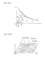
- Fig. 19(a) does not always agree with histograms obtained by this invention, because in Fig. 19(a) histograms H which are weighted with brightness value data (brightness change ratios) of the picture elements of the original picture with respect to the points of intersection appearing every unit of the ⁇ - ⁇ plane are expressed in the contour for easy understanding.
- the histogram at the point P1 in Fig. 19(a) is high and also high at the points P2 and P3.
- the points P4 and P5. what is especially important is to find the points P1 ⁇ P3 spaced from each other.
- the point P1 corresponds to the shoulder lines of the road; the point P2, the center line thereof; and the point P3, the shoulder lines of the forward curved portion of the road.
- the points P4 and P5 correspond to partial curves of the shoulder lines, which are, in many cases, noise components in picture processing.
- An eight neighboring peak filtering for example, lessens such noise components. That is, using an eight neighboring peaks filter as shown in Fig. 19(b), the histograms at the points of intersections of the Hough curves are compared between areas F1 ⁇ F9. When the formula F5 > F1 ⁇ F4 , F6 ⁇ F9 is satisfied, the data in the area F5 is to be detected.
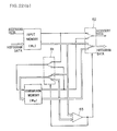
- a signal reading circuit 71 is affixed to the histogram memory (RAM 34) of Fig. 17, and data read from the signal reading circuit 71 is supplied to a shift register 74 having nine storing region (F1 ⁇ F9) through the line buffer 72.
- the histogram data D M of the registers F1 ⁇ F4 and those D M of the shift registers F6 ⁇ F9 are inputted to the comparators C1 ⁇ C4 and C6 ⁇ C9 respectively.
- the histogram data of the shift register F5 is inputted to all the comparators.
- Step 118 in Fig 13 The sorting processing of Step 118 in Fig 13 will be explained below with reference to the flow chart of Fig. 21.
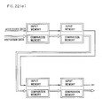
- Step 152 For the sorting processing, a plurality of input memories (transfer memories) M I1 ⁇ M I4 (4 for simplicity), and comparison memory (result memories) M M1 ⁇ M M4 (4 for simplicity) are initialized (Step 152). Next, data is inputted to the input memory M I1 (Step 154). When it is judged that this input data is present in Step 156, Steps 158 ⁇ 184 will follow, and when judged this input data is absent, Steps 190 ⁇ 199 will follow. Steps 190, 196 and 199 perform the same processing as Steps 158 and 160 respectively. Steps 192 and 198 perform the same processing as Step 162 ⁇ 168 respectively. Step 194 performs the same processing as Steps 170 ⁇ 176.
- Steps 158, 162, 170 and 178 respectively compare the magnitudes of the content of the corresponding input memory M I and that of the comparison memory M M and finds M I ⁇ M M , the content of the input memory M I is transferred to the next Steps 164,172 and 180. Contrary to this, when M I > M M , the content of the comparison memory M M is transferred to the next input memory M I (Steps 168, 176, 184). Finally the memories M M1 ⁇ M M4 hold 4 input data in the sequential order of the magnitude.
- Fig. 22(a) four memories M I1 ⁇ M I4 as the input memories, and four memories M M1 ⁇ M M4 as the comparison memories are provided.
- the input memories and comparison memories are mated respectively in four stages of circuits.
- Each stage of circuits, as shown in Fig 22(b), comprises a pair of the input memory M I and the comparison memory M M , switching circuits 81, 82, and a comparator 83.
- the comparator 83 When data inputted to the input memory M I is larger than the data stored by the comparison memory M M , the comparator 83 supplies an output which actuates the switching circuit 81 as indicated by a solid line in Fig. 22(b) and the input data is stored by the comparison memory M M . At the same time, since the switching circuit 82 is in the state as indicated by a solid line, the data stored by the comparison memory M M is transferred to a next stage. In contrast to this, when input data (to the input memory M I ) is smaller than the data stored in the comparison memory M M M , the comparator 83 controls the switching circuits 81, 82 to be in the states indicated by dot lines. The input data is transferred directly to a next stage. The content of the comparison memory M M does not change.
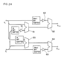
- Fig. 24 is a circuit diagram of the computing device according to an embodiment of this invention.
- the first computing means comprises a first inverter 61 for sign inverting coordinate data y i shifted by m bits, a first adder 51 for adding the coordinate data x i and an output of the first inverter 61, a second inverter 62 for sign inverting coordinate data x i shifted by 2m+1 bits, and a second adder 52 for receiving an output of the first adder 51 and an output of the second inverter 62 to output coordinate data x i+1 .
- the second computing means comprises a third adder for adding the coordinate data y i and coordinate data x i shifted by m bits, a third inverter 63 for sign inverting coordinate data y i shifted by 2m+1 bits, and a fourth adder for adding an output of the third adder 53 and an output of the third inverter 63.
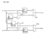
- Figs . 25 and 26 show modifications of the device according to the embodiment.
- the modification of Fig. 25 is different from the device of Fig. 24 in that in the modification the inverters 61. 62 and 63 are omitted, and the adders 51, 52 and 54 are replaced by subtractors 51a, 52a and 54a.
- the modification of Fig. 26 has a circuit comprising inverters 71, 72 and 73, and three input adders 81 and 82.
- the circuit of Fig. 26 can compute the recurrence formula at the same high speed as that of Fig. 24.
- the embodiment of Fig. 27 is different from the embodiment of Fig. 24 and its modifications of Figs. 25 and 26 in that in the embodiment of Fig. 27 the first computing means additionally includes a first divider 65 for multiplying coordinate data y i shifted by 3m bits, and a fifth adder 55 for adding an output of the first divider 65 and an output of the second adder 52, and the second computing means additionally includes a second divider 66 for coordinate data x i shifted by 3m and sign inverted by an inverter 99 and a sixth adder 56 for adding an output of the second divider 66 and an output of the fourth adder 54.
- the first computing means additionally includes a first divider 65 for multiplying coordinate data y i shifted by 3m bits, and a fifth adder 55 for adding an output of the first divider 65 and an output of the second adder 52
- the second computing means additionally includes a second divider 66 for coordinate data x i shifted by 3m and sign inverted by an inverter 99 and a sixth
- the computing device according to the second embodiment comprises two sets of three stage adders, and the dividers. This results in making the device more complicated in comparison with that according to the first embodiment in hardware, and the computation speed accordingly lowers. But the greatly improved computation precision, as stated in Fig. 9, is an advantageous effect of the device according to the second embodiment.
- Fig. 28 is a circuit diagram of a different example of the embodiment of Fig. 24.
- the first computing means comprises a first inverter 61 shifting the coordinate data y i by m bits and inverting the same; a first adder 51 for adding the coordinate data x i , and an output of the first inverter 61; a second inverter 62 for inverting an output of the adder 51; and a second adder for receiving coordinate data shifted by 2m+1 bits, and an output of the second inverter 62 to output coordinate data x i+1 .
- the second computing means comprises a third adder 53 for adding the coordinate data y i , and coordinate data x i shifted by m bits; a third inverter 63 for inverting an output of the third adder 53; and a fourth adder 54 for adding coordinate data shifted by 2m+1 bits, and an output of the third inverter 63.
- the device of Fig. 28 can compute Rotary Motion Recurrence Formulas 33 and 34.
- Fig. 29 shows another different example of the embodiment of Fig. 24.
- the device of Fig. 29 has a circuit comprising inverters 71, 72, 73, and three input adders 81, 82.
- This circuit can compute Formulas 13 and 14, as the circuit of Fig. 28 can.
- the first computing means additionally includes a first divider 65 for multiplying by 1/6 coordinate data y i shifted by 3m bits, and a fifth adder for adding an output of the first divider 65, and an output of the second adder 52
- the second computing means additionally includes a second divider 66 for multiplying by1/6 coordinate data x i shifted by 3m bits and inverted by the inverter 63; and a sixth adder 56 for adding an output of the second divider 66, and an output of the fourth adder 54.
- This example can compute the Rotary Motion Recurrence Formulas 35 and 36.
- two valued data may be multiplexed so that the histogram is based on density of points of intersection.
- data corresponding to the brightness may be digitally processed as brightness data, and then histograms may be obtained at points of intersection of Hough curves.
Landscapes
- Engineering & Computer Science (AREA)
- Theoretical Computer Science (AREA)
- Physics & Mathematics (AREA)
- General Physics & Mathematics (AREA)
- General Engineering & Computer Science (AREA)
- Mathematical Optimization (AREA)
- Computational Mathematics (AREA)
- Mathematical Analysis (AREA)
- Pure & Applied Mathematics (AREA)
- Multimedia (AREA)
- Computer Hardware Design (AREA)
- Computing Systems (AREA)
- Mathematical Physics (AREA)
- Image Analysis (AREA)
Applications Claiming Priority (4)
| Application Number | Priority Date | Filing Date | Title |
|---|---|---|---|
| JP176351/88 | 1988-07-15 | ||
| JP17635188 | 1988-07-15 | ||
| JP18324188A JPH0232481A (ja) | 1988-07-22 | 1988-07-22 | ピークデータ抽出装置 |
| JP183241/88 | 1988-07-22 |
Publications (2)
| Publication Number | Publication Date |
|---|---|
| EP0351228A2 true EP0351228A2 (de) | 1990-01-17 |
| EP0351228A3 EP0351228A3 (de) | 1992-12-23 |
Family
ID=26497309
Family Applications (1)
| Application Number | Title | Priority Date | Filing Date |
|---|---|---|---|
| EP19890307147 Withdrawn EP0351228A3 (de) | 1988-07-15 | 1989-07-14 | Vorrichtung zur Spitzendatenermittlung und Vorrichtung zur Berechnung einer rekursiven Rotativbewegungsformel |
Country Status (1)
| Country | Link |
|---|---|
| EP (1) | EP0351228A3 (de) |
Cited By (1)
| Publication number | Priority date | Publication date | Assignee | Title |
|---|---|---|---|---|
| EP0444593A3 (en) * | 1990-02-26 | 1993-07-21 | Fujitsu Limited | A data processing device |
Family Cites Families (1)
| Publication number | Priority date | Publication date | Assignee | Title |
|---|---|---|---|---|
| GB2135087B (en) * | 1983-02-02 | 1986-02-05 | Marconi Avionics | Vector rotator/accumulator |
-
1989
- 1989-07-14 EP EP19890307147 patent/EP0351228A3/de not_active Withdrawn
Cited By (1)
| Publication number | Priority date | Publication date | Assignee | Title |
|---|---|---|---|---|
| EP0444593A3 (en) * | 1990-02-26 | 1993-07-21 | Fujitsu Limited | A data processing device |
Also Published As
| Publication number | Publication date |
|---|---|
| EP0351228A3 (de) | 1992-12-23 |
Similar Documents
| Publication | Publication Date | Title |
|---|---|---|
| US5247587A (en) | Peak data extracting device and a rotary motion recurrence formula computing device | |
| US5379353A (en) | Apparatus and method for controlling a moving vehicle utilizing a digital differential analysis circuit | |
| US4566124A (en) | Pattern reading system | |
| WO1995016234A1 (en) | Apparatus and method for signal processing | |
| US5642444A (en) | Specialized image processing system architecture and method for image data arrays | |
| US5220615A (en) | Apparatus for and method of hough-converting coordinate data | |
| Pao et al. | A decomposable parameter space for the detection of ellipses | |
| Zhou et al. | An efficient implementation of the gradient-based Hough transform using DSP slices and block RAMs on the FPGA | |
| EP0351228A2 (de) | Vorrichtung zur Spitzendatenermittlung und Vorrichtung zur Berechnung einer rekursiven Rotativbewegungsformel | |
| Li et al. | Hardware design of a 2-D motion estimation system based on the Hough transform | |
| JP2935847B2 (ja) | 画像処理装置 | |
| Hanahara et al. | High-speed Hough transform processor and its applications to automatic inspection and measurement | |
| Ermolin et al. | The use of image processing in tracking | |
| US5206916A (en) | Modular cellular automation for line association and identification | |
| US5438682A (en) | Data processing system for rewriting parallel processor output data using a sequential processor | |
| EP0365878A2 (de) | Bildverarbeitungsverfahren | |
| US4941116A (en) | Elliptical arc generator for display systems | |
| Takala et al. | Distance transform algorithm for Bit-Serial SIMD architectures | |
| KR100206258B1 (ko) | 화상추출장치 | |
| Seaidoun | A fast exact Euclidean distance transform with application to computer vision and digital image processing | |
| JPS623475B2 (de) | ||
| Molz et al. | System Prototyping dedicated to Neural Network Real-Time Image Processing | |
| JPH0644291B2 (ja) | 画像処理装置 | |
| JPH0232481A (ja) | ピークデータ抽出装置 | |
| Khai et al. | A Road Self-Guided Hardware-Based Demo System |
Legal Events
| Date | Code | Title | Description |
|---|---|---|---|
| PUAI | Public reference made under article 153(3) epc to a published international application that has entered the european phase |
Free format text: ORIGINAL CODE: 0009012 |
|
| AK | Designated contracting states |
Kind code of ref document: A2 Designated state(s): DE FR GB |
|
| PUAL | Search report despatched |
Free format text: ORIGINAL CODE: 0009013 |
|
| AK | Designated contracting states |
Kind code of ref document: A3 Designated state(s): DE FR GB |
|
| 17P | Request for examination filed |
Effective date: 19930602 |
|
| 17Q | First examination report despatched |
Effective date: 19930806 |
|
| STAA | Information on the status of an ep patent application or granted ep patent |
Free format text: STATUS: THE APPLICATION IS DEEMED TO BE WITHDRAWN |
|
| 18D | Application deemed to be withdrawn |
Effective date: 19941018 |