EP0351279A1 - Verfahren zur Montage von mindestens einem elektrischen Gerät auf einem Träger. - Google Patents
Verfahren zur Montage von mindestens einem elektrischen Gerät auf einem Träger. Download PDFInfo
- Publication number
- EP0351279A1 EP0351279A1 EP89401873A EP89401873A EP0351279A1 EP 0351279 A1 EP0351279 A1 EP 0351279A1 EP 89401873 A EP89401873 A EP 89401873A EP 89401873 A EP89401873 A EP 89401873A EP 0351279 A1 EP0351279 A1 EP 0351279A1
- Authority
- EP
- European Patent Office
- Prior art keywords
- chassis
- uprights
- support
- envelope
- frame
- Prior art date
- Legal status (The legal status is an assumption and is not a legal conclusion. Google has not performed a legal analysis and makes no representation as to the accuracy of the status listed.)
- Granted
Links
- 238000009434 installation Methods 0.000 title claims abstract description 18
- 238000000034 method Methods 0.000 title claims description 13
- 238000004873 anchoring Methods 0.000 claims description 15
- 125000006850 spacer group Chemical group 0.000 claims description 2
- 239000007943 implant Substances 0.000 claims 1
- 230000008901 benefit Effects 0.000 description 5
- 238000003466 welding Methods 0.000 description 3
- 238000012423 maintenance Methods 0.000 description 2
- 230000006978 adaptation Effects 0.000 description 1
- 239000000470 constituent Substances 0.000 description 1
- 238000010276 construction Methods 0.000 description 1
- 238000002513 implantation Methods 0.000 description 1
- 238000011065 in-situ storage Methods 0.000 description 1
- 210000000056 organ Anatomy 0.000 description 1
- 239000007858 starting material Substances 0.000 description 1
- 238000003860 storage Methods 0.000 description 1
Images

Classifications
-
- H—ELECTRICITY
- H02—GENERATION; CONVERSION OR DISTRIBUTION OF ELECTRIC POWER
- H02B—BOARDS, SUBSTATIONS OR SWITCHING ARRANGEMENTS FOR THE SUPPLY OR DISTRIBUTION OF ELECTRIC POWER
- H02B1/00—Frameworks, boards, panels, desks, casings; Details of substations or switching arrangements
- H02B1/26—Casings; Parts thereof or accessories therefor
- H02B1/40—Wall-mounted casings; Parts thereof or accessories therefor
- H02B1/42—Mounting of devices therein
-
- H—ELECTRICITY
- H02—GENERATION; CONVERSION OR DISTRIBUTION OF ELECTRIC POWER
- H02B—BOARDS, SUBSTATIONS OR SWITCHING ARRANGEMENTS FOR THE SUPPLY OR DISTRIBUTION OF ELECTRIC POWER
- H02B1/00—Frameworks, boards, panels, desks, casings; Details of substations or switching arrangements
- H02B1/20—Bus-bar or other wiring layouts, e.g. in cubicles, in switchyards
- H02B1/202—Cable lay-outs
Definitions
- the present invention relates, in general, to the installation, on any support, for example a wall, of at least any electrical apparatus to be connected to at least one supply cable and at least one connection cable. departure, themselves to "pull”, that is to say, to install, on this support.
- the incoming cable supplies the electrical equipment concerned, while the outgoing cable connects it to the organs or devices it serves.
- the electrical equipment concerned is carried by a chassis made integral with this support by the envelope in which they are then placed.
- this envelope commonly known as a cabinet or box, forms a unit in one piece, its bottom being rigidly connected to the rest of its covering.
- this cabling comes from two different trades, that of incoming cables and outgoing cables being more specifically provided by an installer, who necessarily intervenes in situ, on the site concerned, while that of distribution cables is more specifically provided by a panel builder, who can also intervene on site, but who can also, if desired, execute the corresponding wiring in the workshop.
- the envelope is reconstituted, bringing back on legs, integral with the bottom, the necessary side panels.
- the present invention generally relates to a provision which, on the contrary, facilitates operations on the site and which also leads to other advantages.
- the firstly relates to a process for the installation, on a support, of at least any electrical apparatus to be connected to at least one incoming cable and at least one outgoing cable, of the kind according to which, at the end of such an installation, said electrical equipment, carried by a chassis integral with said support, is disposed within an envelope comprising a bottom and a covering both lateral and frontal, this method being of a generally characterized in that which is first fixed to the support to be fitted to the bottom of the envelope, the chassis is attached to this bottom, which, in parallel and independently, has been fitted with the relevant apparatus and cable accordingly, and then it is put in place the corresponding dressing; it also relates to a font and a frame specific to the implementation of such a method.
- the bottom of the final envelope forms a completely separate element of the chassis to be fitted, and this chassis is equipped and cable independently of this bottom, before being attached to it.
- this chassis having, moreover, by itself, in a manner known per se, all the desirable rigidity, the work of the panel builder, whether carried out in the workshop or on the site, is facilitated by the absence of any dressing as well as by the absence of any background.
- the base according to the invention can advantageously be placed on the support to be fitted even before the draw of the incoming cables and the starting cables thereon.
- the arrangement according to the invention also advantageously promotes a modular construction of these installations.
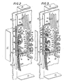
- the electrical equipment 11 concerned must be placed within an envelope 14 comprising a bottom 15 and a covering both lateral and frontal 16.
- the covering 16 of this envelope 14 can for example comprise, laterally, side panels 17 and, frontally, a front plate 18 with openings 19 giving access to the front part of the electrical equipment 11.
- a port 20 duly mounted to pivot on one of its sides, can, if desired, complete such a covering 16.
- the bottom 15 forms a separate component of this covering 16, and, in the embodiment shown, the side panels 17 and the faceplate 18 belonging to this covering 16 themselves form separate components from each other .
- the bottom 15 comprises, rigidly secured to one another, on the one hand, a plate 22, of generally quadrangular outline, and, on the other hand, surrounding this plate 22 at its periphery, by projecting slightly therefrom, a frame 23.
- the base 15 thus formed has, from place to place, on its plate 22, and for example in the corner areas thereof, holes 24 suitable for the passage of means of fixing, screws for example, suitable.
- the electrical equipment 11 to be installed must, moreover, be carried by a chassis 25.
- this chassis 25 comprises, parallel to one another, in the embodiment shown, two uprights 26, with, from one to the other of these uprights, at least one rail 27 suitable for receiving, for example by simple snap-fastening, the electrical equipment 11 concerned.
- the uprights 26 are U-shaped profiles on which are mounted, from place to place, for example by snap-fastening, studs 29 specific to the establishment, from one to the other, rails 27.
- the bottom 15 includes, projecting, anchoring means suitable for bringing the chassis 25 there.
- these anchoring means comprise a plurality of anchoring studs 32 established from place to place on the bottom 15.
- anchoring studs 32 are thus provided, being established, each respectively, in the corner zones of the plate 22 of this base 15.
- Each of them is in the form of a U-shaped piece.
- such a free space 36 can be used for the implantation, projecting from the bottom 15, of clean housing means on receipt of at least one cable.
- these housing means comprise a plurality of lyres 37, three in number for example, and all of them identical, established from place to place along the edge concerned of the bottom 15, in projection on the plate 22 thereof.
- each of these lyres 37 is for example in the form of a U-shaped part, the middle part 38 of which, applied to the plate 22 of the bottom 15, serves for their attachment thereto. , and whose ballast wings 39 extend perpendicular to this plate 22.
- the wings 39 of these lyres 37 have, generally in the direction of one another, in the embodiment shown, elastically deformable returns 40 which slightly overlap each other at their own end.
- the uprights 26 of the chassis 25 each have, on their median part 42, two buttonholes 43 suitable for their engagement on such an anchoring stud 32, with , established from one of their wings 44 to the other, in line with these buttonholes 43, an axis 45 suitable for hooking them on the hooks 35 formed by the wings 34 of these anchoring studs 32.
- the frame 25 further comprises, perpendicular to the plane formed by its uprights 26, pillars 46 suitable for forming spacers for a frame 47, which, for reasons which will appear later, is to be attached to it.
- the chassis 25 thus comprises a pillar 46 at each of the ends of each of its uprights 26.
- Such a pillar 46 may for example be constituted by a section of profile, and it is suitably secured, for example by welding, or screwing, to the amount 26 concerned.
- the rails 27 used already provide, by themselves, a certain bracing of the uprights 26, and therefore therefore contribute to the overall rigidity of the chassis 25, there is preferably provided, between these uprights 26, at least one crosspiece 48 suitable for autonomous stiffening of this chassis 25.
- they are each respectively established from one pillar 46 to another, at a distance from the plane formed by the uprights 26.
- the crosspieces 48 can for example be constituted by sections of profile, and they are suitably secured, for example by welding, or screwing, to these pillars 46.
- the chassis 25 thus produced has by itself all the desired rigidity to allow a standing station, which facilitates transport and storage, and which also facilitates the work of the panel builder who then to equip it with rails 27, electrical equipment 11, and, optionally, chutes 30 ′.
- the frame 47 is intended to be attached to the pillars 46 of this chassis 25, at the end thereof.
- this frame 47 along the inner contour of this frame 47 is connected a generally truncated-pyramidal wall 50 which itself carries, at its end, recessed with respect to the frame 47, and parallel to the latter , a second frame 51 suitable for receiving, for example by simple snap-fastening, the faceplate
- the frame 47 thus used is preferably used for the establishment and maintenance of the side panels 17.
- these side panels 17 can be pinched between this frame 47 and the bottom 15, while being jointly engaged, for example by interlocking or snap-fastening, with the one and / or the other of these.
- the bottom 15 of the casing 14 to be formed is first fixed to the support 10 to be fitted.
- the electrical equipment 11 is connected to these incoming cables 12 and to these outgoing cables 13 is done indirectly.
- connection cables 13 ′ which are for example cables in advance on the electrical equipment 11 concerned, and which it is therefore sufficient to connect to the corresponding terminal block 55.
- connection cables 12 ′ which are for example wired in advance on the electrical equipment 11 concerned, and which it suffices to connect to the corresponding terminal block 53.
- plug-in connection elements can be used.
- one of the free spaces 36 present on either side of the chassis 25 is used for the installation, on the bottom 15, before the installation on it.
- connection cables 13 ′ from these terminal blocks 55 to the electrical equipment 11.
- connection of the incoming cables 12 to these electrical devices 11 is also made directly.
Landscapes
- Engineering & Computer Science (AREA)
- Power Engineering (AREA)
- Installation Of Indoor Wiring (AREA)
- Casings For Electric Apparatus (AREA)
Applications Claiming Priority (2)
| Application Number | Priority Date | Filing Date | Title |
|---|---|---|---|
| FR8808943 | 1988-07-01 | ||
| FR8808943A FR2633783B1 (fr) | 1988-07-01 | 1988-07-01 | Procede pour l'installation, sur un support, d'au moins un appareillage electrique, et fond et chassis propres a la mise en oeuvre d'un tel procede |
Publications (2)
| Publication Number | Publication Date |
|---|---|
| EP0351279A1 true EP0351279A1 (de) | 1990-01-17 |
| EP0351279B1 EP0351279B1 (de) | 1993-02-03 |
Family
ID=9367990
Family Applications (1)
| Application Number | Title | Priority Date | Filing Date |
|---|---|---|---|
| EP19890401873 Expired - Lifetime EP0351279B1 (de) | 1988-07-01 | 1989-06-29 | Verfahren zur Montage von mindestens einem elektrischen Gerät auf einem Träger. |
Country Status (4)
| Country | Link |
|---|---|
| EP (1) | EP0351279B1 (de) |
| DE (1) | DE68904706T2 (de) |
| ES (1) | ES2039895T3 (de) |
| FR (1) | FR2633783B1 (de) |
Cited By (11)
| Publication number | Priority date | Publication date | Assignee | Title |
|---|---|---|---|---|
| FR2662327A1 (fr) * | 1990-05-16 | 1991-11-22 | Legrand Sa | Coffret pour appareils electriques, a fond fonctionnel. |
| FR2664123A1 (fr) * | 1990-07-02 | 1992-01-03 | Merlin Gerin | Coffret basse tension. |
| FR2664122A1 (fr) * | 1990-07-02 | 1992-01-03 | Merlin Gerin | Chassis de fixation d'appareils electriques dans un coffret. |
| FR2664121A1 (fr) * | 1990-07-02 | 1992-01-03 | Merlin Gerin | Coffret d'appareils electriques basse tension. |
| FR2679728A1 (fr) * | 1991-07-22 | 1993-01-29 | Merlin Gerin | Chassis d'appareillage, notamment pour coffret electrique. |
| BE1005858A3 (fr) * | 1990-05-16 | 1994-02-22 | Legrand Sa | Coffret pour appareils electriques, a habillage exterieur presentant au moins une plaque amovible. |
| FR2738409A1 (fr) * | 1995-08-29 | 1997-03-07 | Legrand Sa | Coffret, notamment pour appareils electriques |
| EP0965254A1 (de) | 1997-03-06 | 1999-12-22 | Willsher & Quick Ltd. | Gehäuse für eine telekommunikationsanlage |
| EP1306949A1 (de) * | 2001-10-24 | 2003-05-02 | Karl Kuklies GmbH | Zähler- und/oder Verteilervorrichtung |
| AT414286B (de) * | 2003-10-01 | 2006-11-15 | Moeller Gebaeudeautomation Kg | Basisrahmen eines verteilers |
| EP3672002A1 (de) * | 2018-12-21 | 2020-06-24 | IZYX Systems | Stromverteilungskasten |
Families Citing this family (2)
| Publication number | Priority date | Publication date | Assignee | Title |
|---|---|---|---|---|
| USD344929S (en) | 1992-01-08 | 1994-03-08 | Power Integrity Corp. | Power surge protector |
| CN118137301B (zh) * | 2024-03-21 | 2024-08-23 | 思孚工业电气设备(青岛)有限责任公司 | 一种电力设备用低压柜 |
Citations (3)
| Publication number | Priority date | Publication date | Assignee | Title |
|---|---|---|---|---|
| US2871284A (en) * | 1952-05-09 | 1959-01-27 | Fed Electric Prod Co | Enclosed panelboard mounting |
| EP0143718A2 (de) * | 1983-12-01 | 1985-06-05 | Merlin Gerin | Bei der Installation montierbares Gehäuse für elektrisches Gerät |
| FR2579839A1 (fr) * | 1985-04-01 | 1986-10-03 | France Etat Armement | Tableau d'appareillage et de distribution d'energie electrique basse tension |
-
1988
- 1988-07-01 FR FR8808943A patent/FR2633783B1/fr not_active Expired - Fee Related
-
1989
- 1989-06-29 DE DE1989604706 patent/DE68904706T2/de not_active Expired - Fee Related
- 1989-06-29 EP EP19890401873 patent/EP0351279B1/de not_active Expired - Lifetime
- 1989-06-29 ES ES89401873T patent/ES2039895T3/es not_active Expired - Lifetime
Patent Citations (3)
| Publication number | Priority date | Publication date | Assignee | Title |
|---|---|---|---|---|
| US2871284A (en) * | 1952-05-09 | 1959-01-27 | Fed Electric Prod Co | Enclosed panelboard mounting |
| EP0143718A2 (de) * | 1983-12-01 | 1985-06-05 | Merlin Gerin | Bei der Installation montierbares Gehäuse für elektrisches Gerät |
| FR2579839A1 (fr) * | 1985-04-01 | 1986-10-03 | France Etat Armement | Tableau d'appareillage et de distribution d'energie electrique basse tension |
Cited By (19)
| Publication number | Priority date | Publication date | Assignee | Title |
|---|---|---|---|---|
| BE1005858A3 (fr) * | 1990-05-16 | 1994-02-22 | Legrand Sa | Coffret pour appareils electriques, a habillage exterieur presentant au moins une plaque amovible. |
| FR2662327A1 (fr) * | 1990-05-16 | 1991-11-22 | Legrand Sa | Coffret pour appareils electriques, a fond fonctionnel. |
| FR2664123A1 (fr) * | 1990-07-02 | 1992-01-03 | Merlin Gerin | Coffret basse tension. |
| FR2664122A1 (fr) * | 1990-07-02 | 1992-01-03 | Merlin Gerin | Chassis de fixation d'appareils electriques dans un coffret. |
| FR2664121A1 (fr) * | 1990-07-02 | 1992-01-03 | Merlin Gerin | Coffret d'appareils electriques basse tension. |
| EP0465386A1 (de) * | 1990-07-02 | 1992-01-08 | Merlin Gerin | Niederspannungsgehäuse |
| EP0465387A1 (de) * | 1990-07-02 | 1992-01-08 | Merlin Gerin | Fixierrahmen für elektrische Geräte in einem Kasten |
| EP0465378A1 (de) * | 1990-07-02 | 1992-01-08 | Schneider Electric Sa | Gehäuse für elektrische Niederspannungsgeräte |
| US5147981A (en) * | 1990-07-02 | 1992-09-15 | Merlin Gerin | Low voltage electrical switchgear cabinet |
| FR2679728A1 (fr) * | 1991-07-22 | 1993-01-29 | Merlin Gerin | Chassis d'appareillage, notamment pour coffret electrique. |
| EP0533591A1 (de) * | 1991-07-22 | 1993-03-24 | Schneider Electric Sa | Gerätechassis, insbesondere für elektrischen Behälter |
| FR2738409A1 (fr) * | 1995-08-29 | 1997-03-07 | Legrand Sa | Coffret, notamment pour appareils electriques |
| EP0762586A1 (de) * | 1995-08-29 | 1997-03-12 | Legrand | Gehäuse für elektrische Geräte |
| EP0965254A1 (de) | 1997-03-06 | 1999-12-22 | Willsher & Quick Ltd. | Gehäuse für eine telekommunikationsanlage |
| US6348655B1 (en) | 1997-03-06 | 2002-02-19 | Willsher & Quick Ltd. | Enclosure for telecommunications equipment |
| EP1306949A1 (de) * | 2001-10-24 | 2003-05-02 | Karl Kuklies GmbH | Zähler- und/oder Verteilervorrichtung |
| AT414286B (de) * | 2003-10-01 | 2006-11-15 | Moeller Gebaeudeautomation Kg | Basisrahmen eines verteilers |
| WO2005032229A3 (de) * | 2003-10-01 | 2009-03-05 | Moeller Gebaeudeautomation Kg | Basisrahmen eines verteilers |
| EP3672002A1 (de) * | 2018-12-21 | 2020-06-24 | IZYX Systems | Stromverteilungskasten |
Also Published As
| Publication number | Publication date |
|---|---|
| FR2633783B1 (fr) | 1991-05-17 |
| DE68904706T2 (de) | 1993-05-19 |
| ES2039895T3 (es) | 1993-10-01 |
| EP0351279B1 (de) | 1993-02-03 |
| DE68904706D1 (de) | 1993-03-18 |
| FR2633783A1 (fr) | 1990-01-05 |
Similar Documents
| Publication | Publication Date | Title |
|---|---|---|
| EP0351279B1 (de) | Verfahren zur Montage von mindestens einem elektrischen Gerät auf einem Träger. | |
| EP0143718B1 (de) | Bei der Installation montierbares Gehäuse für elektrisches Gerät | |
| EP2299552B1 (de) | Gehäuse zur Aufnahme eines Niedrigspannungsgeräts, das mit einer Schaltgerätzelle mittlerer Spannung verbunden ist | |
| FR3003407A1 (fr) | Enveloppe electrique a agencement mecanique ameliore | |
| FR2711036A3 (fr) | Bâti pour une armoire à appareillage servant au montage de porte-ensemble de l'électronique industrielle. | |
| FR2758660A1 (fr) | Panneau modulaire de brassage, pour reseaux de donnees | |
| EP0465378A1 (de) | Gehäuse für elektrische Niederspannungsgeräte | |
| EP0237410A1 (de) | Gehäuse für elektrische Geräte | |
| FR2702314A1 (fr) | Armoire métallique, notamment pour le logement d'un appareillage électrique modulaire. | |
| EP2383849B1 (de) | Vertikale elektrisch leitenden Verbindungsvorrichtung | |
| EP0651482B1 (de) | Trägervorrichtung für elektrische Geräte | |
| EP0989647B1 (de) | Rahmengestell, insbesondere für ein Elektrogerät | |
| EP1107363A1 (de) | Monopolarer Modularerverteiler | |
| FR2690287A1 (fr) | Boîtier de dalle ou de sol pour raccordement d'équipements téléphoniques et/ou informatiques, dalle de faux plancher équipée d'un tel boîtier, et procédé pour réaliser un précablage de locaux à l'aide d'un tel boîtier. | |
| EP4064479A1 (de) | Trägerkasten, anschlussschrank mit einem solchen trägerkasten und verfahren zum zusammenbau eines solchen anschlussschranks | |
| EP0730329B1 (de) | Kanal für das auf Putz oder unter Putz Montieren von elektrischen Gehäusen oder dergleichen in Etagenwohnungen, Wohnhäusern, Geschäften oder industriellen Anlagen | |
| WO2021069507A1 (fr) | Support d'appareillage electrique | |
| FR2581233A1 (fr) | Bride isolante pour barres conductrices, notamment pour tableaux de distribution | |
| FR2973920A1 (fr) | Dispositif d'adaptation de moniteur nouveau format dans les installations de monitorage existantes | |
| FR2806545A1 (fr) | Chassis, notamment pour appareillage electrique, et ensemble de consoles gauche et droite pour la fixation d'un tel chassis sur une paroi | |
| EP1583192B1 (de) | Schaltschrank mit Kabeldurchführungen | |
| FR2667633A1 (fr) | Panneau de cloison et cloison demontable comprenant au moins un tel panneau. | |
| FR2738102A1 (fr) | Dispositif de montage pour equipement, en particulier appareillage electrique, a rapporter sur un chassis de support a barreaux, et platine de support correspondante | |
| EP3186861B1 (de) | Versorgungssäule für modularen aufbau, für messestände | |
| EP1641094B1 (de) | Kasten zum Verbinden von elektrischen Kabeln |
Legal Events
| Date | Code | Title | Description |
|---|---|---|---|
| PUAI | Public reference made under article 153(3) epc to a published international application that has entered the european phase |
Free format text: ORIGINAL CODE: 0009012 |
|
| AK | Designated contracting states |
Kind code of ref document: A1 Designated state(s): BE DE ES IT |
|
| 17P | Request for examination filed |
Effective date: 19900209 |
|
| 17Q | First examination report despatched |
Effective date: 19911107 |
|
| RTI1 | Title (correction) | ||
| GRAA | (expected) grant |
Free format text: ORIGINAL CODE: 0009210 |
|
| AK | Designated contracting states |
Kind code of ref document: B1 Designated state(s): BE DE ES IT |
|
| REF | Corresponds to: |
Ref document number: 68904706 Country of ref document: DE Date of ref document: 19930318 |
|
| ITF | It: translation for a ep patent filed | ||
| REG | Reference to a national code |
Ref country code: ES Ref legal event code: FG2A Ref document number: 2039895 Country of ref document: ES Kind code of ref document: T3 |
|
| PLBE | No opposition filed within time limit |
Free format text: ORIGINAL CODE: 0009261 |
|
| STAA | Information on the status of an ep patent application or granted ep patent |
Free format text: STATUS: NO OPPOSITION FILED WITHIN TIME LIMIT |
|
| 26N | No opposition filed | ||
| PGFP | Annual fee paid to national office [announced via postgrant information from national office to epo] |
Ref country code: ES Payment date: 20020610 Year of fee payment: 14 |
|
| PGFP | Annual fee paid to national office [announced via postgrant information from national office to epo] |
Ref country code: DE Payment date: 20020612 Year of fee payment: 14 |
|
| PGFP | Annual fee paid to national office [announced via postgrant information from national office to epo] |
Ref country code: BE Payment date: 20020701 Year of fee payment: 14 |
|
| PG25 | Lapsed in a contracting state [announced via postgrant information from national office to epo] |
Ref country code: ES Free format text: LAPSE BECAUSE OF NON-PAYMENT OF DUE FEES Effective date: 20030630 Ref country code: BE Free format text: LAPSE BECAUSE OF NON-PAYMENT OF DUE FEES Effective date: 20030630 |
|
| BERE | Be: lapsed |
Owner name: *LEGRAND Effective date: 20030630 |
|
| PG25 | Lapsed in a contracting state [announced via postgrant information from national office to epo] |
Ref country code: DE Free format text: LAPSE BECAUSE OF NON-PAYMENT OF DUE FEES Effective date: 20040101 |
|
| REG | Reference to a national code |
Ref country code: ES Ref legal event code: FD2A Effective date: 20030630 |
|
| PGFP | Annual fee paid to national office [announced via postgrant information from national office to epo] |
Ref country code: IT Payment date: 20060630 Year of fee payment: 18 |
|
| PG25 | Lapsed in a contracting state [announced via postgrant information from national office to epo] |
Ref country code: IT Free format text: LAPSE BECAUSE OF NON-PAYMENT OF DUE FEES Effective date: 20070629 |