EP0351325B1 - Vorrichtung zum Herstellen eines ringförmigen Elementes aus Beton, insbesondere einer Schachtauskleidung - Google Patents
Vorrichtung zum Herstellen eines ringförmigen Elementes aus Beton, insbesondere einer Schachtauskleidung Download PDFInfo
- Publication number
- EP0351325B1 EP0351325B1 EP19890420234 EP89420234A EP0351325B1 EP 0351325 B1 EP0351325 B1 EP 0351325B1 EP 19890420234 EP19890420234 EP 19890420234 EP 89420234 A EP89420234 A EP 89420234A EP 0351325 B1 EP0351325 B1 EP 0351325B1
- Authority
- EP
- European Patent Office
- Prior art keywords
- mold
- piston head
- coupling
- cap
- installation according
- Prior art date
- Legal status (The legal status is an assumption and is not a legal conclusion. Google has not performed a legal analysis and makes no representation as to the accuracy of the status listed.)
- Expired - Lifetime
Links
- 230000008878 coupling Effects 0.000 claims abstract description 36
- 238000010168 coupling process Methods 0.000 claims abstract description 36
- 238000005859 coupling reaction Methods 0.000 claims abstract description 36
- 238000009434 installation Methods 0.000 claims abstract description 19
- 238000000465 moulding Methods 0.000 claims abstract description 10
- 238000004519 manufacturing process Methods 0.000 claims description 12
- 238000000034 method Methods 0.000 abstract description 3
- 230000000694 effects Effects 0.000 abstract description 2
- 230000033001 locomotion Effects 0.000 description 5
- 230000005540 biological transmission Effects 0.000 description 2
- 230000006866 deterioration Effects 0.000 description 2
- 230000010355 oscillation Effects 0.000 description 2
- 208000031968 Cadaver Diseases 0.000 description 1
- 230000009471 action Effects 0.000 description 1
- 230000004075 alteration Effects 0.000 description 1
- 230000015556 catabolic process Effects 0.000 description 1
- 230000000295 complement effect Effects 0.000 description 1
- 238000010276 construction Methods 0.000 description 1
- 238000006731 degradation reaction Methods 0.000 description 1
- 230000001627 detrimental effect Effects 0.000 description 1
- 238000006073 displacement reaction Methods 0.000 description 1
- 238000000605 extraction Methods 0.000 description 1
- 230000004048 modification Effects 0.000 description 1
- 238000012986 modification Methods 0.000 description 1
- 230000001681 protective effect Effects 0.000 description 1
Images
Classifications
-
- B—PERFORMING OPERATIONS; TRANSPORTING
- B28—WORKING CEMENT, CLAY, OR STONE
- B28B—SHAPING CLAY OR OTHER CERAMIC COMPOSITIONS; SHAPING SLAG; SHAPING MIXTURES CONTAINING CEMENTITIOUS MATERIAL, e.g. PLASTER
- B28B21/00—Methods or machines specially adapted for the production of tubular articles
- B28B21/02—Methods or machines specially adapted for the production of tubular articles by casting into moulds
- B28B21/10—Methods or machines specially adapted for the production of tubular articles by casting into moulds using compacting means
- B28B21/22—Methods or machines specially adapted for the production of tubular articles by casting into moulds using compacting means using rotatable mould or core parts
- B28B21/24—Methods or machines specially adapted for the production of tubular articles by casting into moulds using compacting means using rotatable mould or core parts using compacting heads, rollers, or the like
-
- B—PERFORMING OPERATIONS; TRANSPORTING
- B28—WORKING CEMENT, CLAY, OR STONE
- B28B—SHAPING CLAY OR OTHER CERAMIC COMPOSITIONS; SHAPING SLAG; SHAPING MIXTURES CONTAINING CEMENTITIOUS MATERIAL, e.g. PLASTER
- B28B21/00—Methods or machines specially adapted for the production of tubular articles
- B28B21/70—Methods or machines specially adapted for the production of tubular articles by building-up from preformed elements
- B28B21/74—Producing pipe bends, sockets, sleeves; Moulds therefor
Definitions
- the invention relates to an installation for manufacturing an annular concrete part, in particular a well nozzle, which comprises, on the one hand, a molding device composed of a mold core and a mold body surrounding the remote mold core to define an annular space and, on the other hand, a mold cap which can rotate around its main axis and intended to be placed on the concrete poured into the annular space, said cap being mounted on a head piston can go up and down and able to form a centering tip in the front region of the annular part.
- the well nozzles and other annular parts which can be aligned axially one after the other, have, at their front ends, directed towards one another, complementary centering nozzles by which the different parts couple to each other.
- molding devices are used which are composed of a mold core and a mold body between which there remains an annular space in which the quantity of concrete necessary for vibrating is vibrated. the room.
- annular space of the molding device can be closed in the region of the bottom by a corresponding mold ring, for the manufacture of the upper centering tip, a mold cap must be applied to the concrete poured into the annular space with an appropriate pressure and rotate this cap around its axis, preferably in reciprocating motion, in order to be able to mold the centering tip with sufficient precision.
- this mold cover is constituted by a rotating ring belonging to a piston head by means of which the necessary contact pressure can be exerted.
- a disadvantage is that, before demolding, it is necessary, necessarily, to lift the piston with the upper cap to release it from the part, so that not only the manufacturing tolerances are widened, but also there remains a risk of deterioration of the molded centering tip because the concrete's own resistance before hardening is relatively low.
- the installation comprises a rotatable mold cap intended to be placed on the poured concrete in an annular space defined between a mold core and a mold body.
- the mold cap is permanently mounted on a piston head by means of controlled rods whose retraction and extension movement ensures the vertical positioning of the mold cap.
- the object of the invention is therefore to avoid these drawbacks and to improve the installations and methods, of the kind described above, using simple means, so that well nozzles or other parts can be manufactured.
- concrete annulars having flawless centering tips and having a high stability of resistance of the dimensional dimensions of manufacture.
- the invention solves the problem posed by the fact that the mold cap is connected to the piston head by a temporary coupling device ensuring, by opening and closing, the gripping or loosening of the mold cap.
- the mold cap Since the mold cap is connected to the piston head by means of a temporary coupling device ensuring an opening or closing, it may not be separate it from the centering tip to unmold the part, so that the stresses detrimental to the holding of the dimensions, which would otherwise act on the concrete not yet hardened in the region of the centering tip during the extraction of the mold cap, are thus deleted. In this way, the mold cap can only be separated from the centering tip after an appropriate hardening of the latter and thanks to the fact that the concrete solidity is now sufficient, there is no longer any alteration of the holding of the dimensions.
- the mold cap which remains on the part, forms, moreover, an effective protection of the centering tip against mechanical deterioration, so that it is possible to effectively avoid hair cracks or other harmful degradations. the strength of the centering tips. It is certainly necessary to provide a separate mold cap for each part, but the number of mold caps required remains limited because, after having been separated from the parts, the mold caps can be used for the manufacture of new parts.
- the coupling device intended to connect a mold cap to the piston head by a removable connection, can be of various construction.
- the mold cap could be provided with coupling lugs which could lock into openings receiving the piston head, this requiring, however, an appropriate alignment of the mold cap relative to the head. piston.
- Simpler coupling conditions are obtained when, in another embodiment of the invention, the coupling device is preferably composed of at least three collets distributed over the periphery of the piston head and who can grasp a mold cap, even if the cap is not exactly aligned with the piston head.
- clamps which are provided between the arms of the clamps which are extended beyond the axes of articulation of the jaws of the clamps and which, when they are supplied, close the clamp jaws against the force of an opening spring, which ensures very simple control of the coupling device.
- the clamps certainly provide self-centering for the mold cap which they grip but, due to the freedom of oscillation of the clamping jaws, the mold cap, gripped by these jaws, will at least partially accompany, the vibration movement of the molding device, which can lead to an undesirable transmission of vibrations to the piston head.
- the clamps can bear, at least in the closed position, against a stop secured to the clamp support by means of stop elements secured to the clamp support, by means of elastic rubber-like elements.
- These elastic elements, of the rubber type can, moreover, define an initial position for the collets.
- the mold caps In order for the coupling device to be able to grip the different mold caps securely, the mold caps must have a corresponding coupling collar.
- the various mold caps may have an annular coupling collar intended for the coupling device, which makes the mold caps independent of an angular position of the coupling which should be determined in advance.
- the coupling device must be able to grip the annular coupling collar, as is the case, for example, for collets.
- the piston head has at least three centering ribs distributed around the circumference and provided with inclined guide surfaces to receive the annular coupling collar of the mold cap, it is already possible to obtain a centering of the mold during the movement. of axial approximation between the mold cap and the piston head, because if the annular coupling collar meets the guide surface of minus a centering rib, while it is in an off-center position, it is pushed towards the axis of the piston head.
- the piston head can finally carry at least three ejector fingers movable in the direction axial, distributed around the circumference, to eject the mold cap, so that, when the piston head is raised, after opening the clamps, the mold cap is kept pressed against the part until the ejector fingers move away from the mold cap.
- the ejector fingers must be controlled by a corresponding force, which is carried out, advantageously, by means of a pressure cylinder.
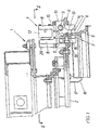
- Fig. 1 shows an installation according to the invention, intended for the manufacture of an annular concrete part, in a schematic axial section of the region of the edge of the piston head.
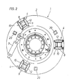
- Fig. 2 is a section, perpendicular to the axis of the piston head, made along line II-II of FIG. 1 , on a reduced scale.
- the piston head 1 which can go up and down under the action of a lifting cylinder not shown, and which is part of the installation shown for the manufacture of a concrete well nozzle, has a rotating crown 2 which can be driven in alternating rotation using an oscillation cylinder 3 shown in FIG. 2 .
- This rotating crown 2 carries a coupling device, preferably formed by three clamps 4 distributed on the circumference and intended to couple to a mold cap 5 which, for this purpose, is provided, in accordance with the representation of fig. 1 , an annular coupling collar 6 which engages between the two jaws 7 of the collets 4 .
- the jaws 7 of pliers are articulated using pivot pins 9 , in a pliers support 10 which is fixed to the rotating ring 2 in the region of a through opening 11 giving passage to the jaws 7 of pliers.
- each of the clamps 4 there is provided a clamping cylinder 12 placed between the arms 8 of the clamps, which extend above the hinge pins 9 , the clamping cylinder 12 acting at the against the force of an opening spring 13 which is interposed between the arms 8 of the clamps, on the side opposite to the clamping cylinder 12 with respect to the articulation axes 9 , in a bore 14 produced in a carrying element 15 .
- the arms 8 of the clamps carry, on their side directed towards the carrying element 15 , elastic elements 16 of the rubber type which cooperate, at least in the closed position of the clamps 4 shown in the figures, with the carrying part 15 playing the role of stop, which excludes, to a large extent, the transmission of the vibration forces acting on the mold sleeve 5 to the rotating ring 2 via the clamps 4 .
- These elastic elements 16 also have the effect of defining an initial position for the jaws 7 of the pliers.
- the rotating crown 2 can be provided with at least three centering ribs 17 distributed over its circumference, which form an inclined guide surface 18 for guiding the coupling collar 6 of the mold cap 5 , so that, if the mold cap 5 is placed in an off-center position relative to the rotating crown 2 , during the movement of arrival of the mold cap 5 , in a direction corresponding to its main axis on the guide surface 18 of at least one centering rib 17 , the coupling collar 6 is pushed back towards the axis of the piston head 1 , at least to a sufficient extent to guarantee the safety of the gripping of the coupling collar 6 by the collets 4 .
- the temporary coupling device ensuring opening or closing functions, formed by the clamps 4 , the mold cap 5 , placed on the concrete poured between a mold core and a surrounding mold body at a distance.
- the mold core can be separated from the piston head 1 , after the upper centering tip of the well nozzle has been molded to the shape of the profile of the mold cap, the cap 5 being able to remain on the collar centering the nozzle, at least during the demolding operation of the nozzle, to form a protective ring.
- the object of the invention finds a particularly advantageous application for the production of centering nozzles formed by forming at the end of well nozzles or the like in concrete.
Landscapes
- Engineering & Computer Science (AREA)
- Manufacturing & Machinery (AREA)
- Chemical & Material Sciences (AREA)
- Ceramic Engineering (AREA)
- Mechanical Engineering (AREA)
- Moulds, Cores, Or Mandrels (AREA)
- Joining Of Building Structures In Genera (AREA)
- Manufacturing Of Tubular Articles Or Embedded Moulded Articles (AREA)
- Forms Removed On Construction Sites Or Auxiliary Members Thereof (AREA)
- Devices For Post-Treatments, Processing, Supply, Discharge, And Other Processes (AREA)
- Press-Shaping Or Shaping Using Conveyers (AREA)
- Wire Processing (AREA)
Claims (8)
dadurch gekennzeichnet, daß die Kopplungsvorrichtung aus einer Anordnung von Klemmzangen (4) gebildet ist, die am Umfang des Kolbenkopfes (3) verteilt angeordnet sind, um durch Öffnen und Schließen das Aufnehmen und Loslassen des Formdeckels (5) sicherzustellen.
Applications Claiming Priority (2)
| Application Number | Priority Date | Filing Date | Title |
|---|---|---|---|
| AT0170288A AT398185B (de) | 1988-06-30 | 1988-06-30 | Vorrichtung zum herstellen eines ringförmigen falzes an einem werkstück aus beton, insbesondere einem schachtring |
| AT1702/88 | 1988-06-30 |
Publications (2)
| Publication Number | Publication Date |
|---|---|
| EP0351325A1 EP0351325A1 (de) | 1990-01-17 |
| EP0351325B1 true EP0351325B1 (de) | 1992-06-03 |
Family
ID=3519135
Family Applications (1)
| Application Number | Title | Priority Date | Filing Date |
|---|---|---|---|
| EP19890420234 Expired - Lifetime EP0351325B1 (de) | 1988-06-30 | 1989-06-30 | Vorrichtung zum Herstellen eines ringförmigen Elementes aus Beton, insbesondere einer Schachtauskleidung |
Country Status (4)
| Country | Link |
|---|---|
| EP (1) | EP0351325B1 (de) |
| AT (2) | AT398185B (de) |
| DE (1) | DE68901691T2 (de) |
| ES (1) | ES2033121T3 (de) |
Families Citing this family (1)
| Publication number | Priority date | Publication date | Assignee | Title |
|---|---|---|---|---|
| EP1223014A1 (de) * | 2001-01-16 | 2002-07-17 | Schlüsselbauer, Johann | Vorrichtung zur Herstellung von Ringkörpern aus Beton |
Family Cites Families (15)
| Publication number | Priority date | Publication date | Assignee | Title |
|---|---|---|---|---|
| US766739A (en) * | 1902-05-20 | 1904-08-02 | Maurice T Stevens | Pipe-mold. |
| GB260791A (en) * | 1925-12-02 | 1926-11-11 | Int De Lavaud Mfg Corp Ltd | Improvements in cores for pipe moulds |
| US1941812A (en) * | 1932-04-21 | 1934-01-02 | Muntz Eric Percival | Machine for the production of a plurality of substantially similar units |
| US2359214A (en) * | 1943-02-03 | 1944-09-26 | Frank C George | Mold core element |
| US2870513A (en) * | 1955-04-28 | 1959-01-27 | Archie R Gagne | Pipe making apparatus |
| FR1190293A (fr) * | 1958-01-21 | 1959-10-12 | Brouiller & Cie | Presse et procédé de fabrication pour former les évasements à cloche sur les tuyaux en ciment |
| DK108118C (da) * | 1963-11-07 | 1967-09-04 | Pedershaab Maskinfabrik As | Støbeapparat til fremstilling af betonrør med en rundtgående not eller hulkel i rørets spidsende. |
| US3452407A (en) * | 1966-09-30 | 1969-07-01 | Concrete Pipe Machinery Co | Ring positioning apparatus for concrete pipe manufacture |
| US3696182A (en) * | 1970-06-29 | 1972-10-03 | Carl R Joelson | Method for producing concrete pipe |
| DK127176B (da) * | 1972-02-09 | 1973-10-01 | Pedershaab Maskinfabrik As | Støttering til nystøbte rør af beton eller lignende materiale under hærdning. |
| US4101622A (en) * | 1974-07-15 | 1978-07-18 | Ameron, Inc. | Method of casting beveled pipe |
| DE3203543A1 (de) * | 1982-02-03 | 1983-08-04 | Georg Prinzing GmbH & Co KG Betonformen- und Maschinenfabrik, 7902 Blaubeuren | Verfahren und vorrichtung zum herstellen von betonformteilen |
| EP0089420A1 (de) * | 1982-03-23 | 1983-09-28 | Ballast-Nedam Groep N.V. | Verfahren, Vorrichtung und Form zur Herstellung von Betonrohren |
| DE3323340A1 (de) * | 1983-06-29 | 1985-01-03 | Georg Prinzing GmbH & Co KG Betonformen- und Maschinenfabrik, 7902 Blaubeuren | Formeinrichtung zum herstellen von betonformteilen |
| DE3400349A1 (de) * | 1984-01-07 | 1985-07-18 | Prinzing Georg Gmbh Co Kg | Verfahren und vorrichtung zum herstellen von formteilen aus beton |
-
1988
- 1988-06-30 AT AT0170288A patent/AT398185B/de not_active IP Right Cessation
-
1989
- 1989-06-30 DE DE8989420234T patent/DE68901691T2/de not_active Expired - Fee Related
- 1989-06-30 EP EP19890420234 patent/EP0351325B1/de not_active Expired - Lifetime
- 1989-06-30 AT AT89420234T patent/ATE76800T1/de not_active IP Right Cessation
- 1989-06-30 ES ES198989420234T patent/ES2033121T3/es not_active Expired - Lifetime
Also Published As
| Publication number | Publication date |
|---|---|
| DE68901691D1 (de) | 1992-07-09 |
| AT398185B (de) | 1994-10-25 |
| ES2033121T3 (es) | 1993-03-01 |
| ATA170288A (de) | 1994-02-15 |
| DE68901691T2 (de) | 1993-02-18 |
| EP0351325A1 (de) | 1990-01-17 |
| ATE76800T1 (de) | 1992-06-15 |
Similar Documents
| Publication | Publication Date | Title |
|---|---|---|
| FR2608485A1 (fr) | Mecanisme de separation d'une porte fixee a une coque | |
| EP0976482B1 (de) | Zentrier- und Spannvorrichtung, insbesondere für Teile beim Wagenaufbau | |
| WO1996035547A1 (fr) | Dispositif d'indexation d'une piece a travers un trou de cette piece | |
| EP0715946A1 (de) | Verfahren zur Herstellung einer optischen Linse aus synthetischem polymerisierbarem Material und entsprechende Vorrichtung | |
| EP4021663B1 (de) | Verbessertes verfahren zur herstellung eines keramischen kerns zur herstellung von turbomaschinenschaufeln und keramischer kern | |
| FR2507520A1 (fr) | Pince pour dispositif de levage destine a la manutention de pieces | |
| EP4372488A1 (de) | Greifervorrichtung zum halten, zentrieren und/oder klemmen eines mikromechanischen bauteils oder einer uhr und zugehöriges befestigungsverfahren | |
| EP0588713B1 (de) | Fräs-, Planfräs- und Polier-Maschine für automatischen Werkzeugwechsel und entsprechende Vorrichtung | |
| FR2832909A1 (fr) | Forme avec dispositif de prehension, pour la fabrication de chaussures | |
| EP0351325A1 (de) | Vorrichtung zum Herstellen eines ringförmigen Elementes aus Beton, insbesondere einer Schachtauskleidung | |
| FR2711123A1 (fr) | Transporteur-culbuteur pour grandes pièces. | |
| FR2720679A1 (fr) | Bras de transfert et machine de fabrication de bouteilles à partir de préforme utilisant un tel bras. | |
| FR2501575A1 (fr) | Appareil pour l'avance et l'orientation de pieces dans une presse | |
| EP0063966B1 (de) | Vorrichtung zum Greifen und Transportieren von Gegenständen und Verfahren zum Entgraten von Giesskernen aus Sand | |
| EP0125549A1 (de) | Tragvorrichtung für einen Muffenkern für Schleudergiessform für gusseiserne Muffenrohre | |
| FR2658587A1 (fr) | Installation pour la manutention de chapeaux de bouteilles a gaz, avant et apres le remplissage de ces bouteilles. | |
| EP0179024B1 (de) | Montagevorrichtung für eine Spannzange zum Spannen eines Werkstückes in einer Werkzeugmaschine | |
| JP2971774B2 (ja) | 高分子材料成形型の離型治具 | |
| FR2587272A1 (fr) | Procede et dispositif de redressement et d'alignement d'une premiere piece en matiere plastique par exemple thermosoudable avec une deuxieme piece en matiere plastique similaire pouvant egalement etre redressee en vue de leur assemblage bout a bout | |
| FR2682057A1 (fr) | Dispositif de positionnement et d'accouplement d'un entrainement. | |
| FR2494614A1 (fr) | Dispositif de chargement et de dechargement de pieces dans une machine a rectifier de production | |
| EP1281480B1 (de) | Spannvorrichtung | |
| EP4039433B1 (de) | Rüttelpresse mit verbesserter regulierung | |
| EP0125559A1 (de) | Mit einer Bremsvorrichtung versehener Roboter | |
| FR2715646A1 (fr) | Dispositif de préhension à mandrin expansible. |
Legal Events
| Date | Code | Title | Description |
|---|---|---|---|
| PUAI | Public reference made under article 153(3) epc to a published international application that has entered the european phase |
Free format text: ORIGINAL CODE: 0009012 |
|
| AK | Designated contracting states |
Kind code of ref document: A1 Designated state(s): AT BE CH DE ES FR GB GR IT LI LU NL SE |
|
| 17P | Request for examination filed |
Effective date: 19900716 |
|
| 17Q | First examination report despatched |
Effective date: 19910326 |
|
| GRAA | (expected) grant |
Free format text: ORIGINAL CODE: 0009210 |
|
| AK | Designated contracting states |
Kind code of ref document: B1 Designated state(s): AT BE CH DE ES FR GB GR IT LI LU NL SE |
|
| PG25 | Lapsed in a contracting state [announced via postgrant information from national office to epo] |
Ref country code: SE Effective date: 19920603 Ref country code: GR Free format text: LAPSE BECAUSE OF FAILURE TO SUBMIT A TRANSLATION OF THE DESCRIPTION OR TO PAY THE FEE WITHIN THE PRESCRIBED TIME-LIMIT Effective date: 19920603 Ref country code: AT Effective date: 19920603 |
|
| REF | Corresponds to: |
Ref document number: 76800 Country of ref document: AT Date of ref document: 19920615 Kind code of ref document: T |
|
| PG25 | Lapsed in a contracting state [announced via postgrant information from national office to epo] |
Ref country code: LU Free format text: LAPSE BECAUSE OF NON-PAYMENT OF DUE FEES Effective date: 19920630 Ref country code: LI Effective date: 19920630 Ref country code: CH Effective date: 19920630 |
|
| REF | Corresponds to: |
Ref document number: 68901691 Country of ref document: DE Date of ref document: 19920709 |
|
| GBT | Gb: translation of ep patent filed (gb section 77(6)(a)/1977) | ||
| RAP2 | Party data changed (patent owner data changed or rights of a patent transferred) |
Owner name: SCHLUSSELBAUER MASCHINENBAU |
|
| REG | Reference to a national code |
Ref country code: CH Ref legal event code: PUE Owner name: SCHLUESSELBAUER MASCHINENBAU |
|
| ITF | It: translation for a ep patent filed | ||
| RAP4 | Party data changed (patent owner data changed or rights of a patent transferred) |
Owner name: SCHLUESSELBAUER MASCHINENBAU |
|
| NLT2 | Nl: modifications (of names), taken from the european patent patent bulletin |
Owner name: SCHLUSSELBAUER MASCHINENBAU TE GASPOLTSHOFEN, OOST |
|
| REG | Reference to a national code |
Ref country code: CH Ref legal event code: PL |
|
| REG | Reference to a national code |
Ref country code: ES Ref legal event code: FG2A Ref document number: 2033121 Country of ref document: ES Kind code of ref document: T3 |
|
| PLBE | No opposition filed within time limit |
Free format text: ORIGINAL CODE: 0009261 |
|
| STAA | Information on the status of an ep patent application or granted ep patent |
Free format text: STATUS: NO OPPOSITION FILED WITHIN TIME LIMIT |
|
| 26N | No opposition filed | ||
| PGFP | Annual fee paid to national office [announced via postgrant information from national office to epo] |
Ref country code: NL Payment date: 20010517 Year of fee payment: 13 |
|
| PGFP | Annual fee paid to national office [announced via postgrant information from national office to epo] |
Ref country code: ES Payment date: 20010608 Year of fee payment: 13 |
|
| PGFP | Annual fee paid to national office [announced via postgrant information from national office to epo] |
Ref country code: BE Payment date: 20010712 Year of fee payment: 13 |
|
| REG | Reference to a national code |
Ref country code: GB Ref legal event code: IF02 |
|
| PG25 | Lapsed in a contracting state [announced via postgrant information from national office to epo] |
Ref country code: BE Free format text: LAPSE BECAUSE OF NON-PAYMENT OF DUE FEES Effective date: 20020630 |
|
| PG25 | Lapsed in a contracting state [announced via postgrant information from national office to epo] |
Ref country code: ES Free format text: LAPSE BECAUSE OF NON-PAYMENT OF DUE FEES Effective date: 20020701 |
|
| BERE | Be: lapsed |
Owner name: *SCHLUSSELBAUER MASCHINENBAU Effective date: 20020630 Owner name: SOC. EN NOM COLLECTIF *SABLA Effective date: 20020630 |
|
| PG25 | Lapsed in a contracting state [announced via postgrant information from national office to epo] |
Ref country code: NL Free format text: LAPSE BECAUSE OF NON-PAYMENT OF DUE FEES Effective date: 20030101 |
|
| NLV4 | Nl: lapsed or anulled due to non-payment of the annual fee |
Effective date: 20030101 |
|
| REG | Reference to a national code |
Ref country code: ES Ref legal event code: FD2A Effective date: 20030711 |
|
| PGFP | Annual fee paid to national office [announced via postgrant information from national office to epo] |
Ref country code: FR Payment date: 20040429 Year of fee payment: 16 |
|
| PGFP | Annual fee paid to national office [announced via postgrant information from national office to epo] |
Ref country code: DE Payment date: 20040609 Year of fee payment: 16 |
|
| PGFP | Annual fee paid to national office [announced via postgrant information from national office to epo] |
Ref country code: GB Payment date: 20040622 Year of fee payment: 16 |
|
| PG25 | Lapsed in a contracting state [announced via postgrant information from national office to epo] |
Ref country code: IT Free format text: LAPSE BECAUSE OF NON-PAYMENT OF DUE FEES;WARNING: LAPSES OF ITALIAN PATENTS WITH EFFECTIVE DATE BEFORE 2007 MAY HAVE OCCURRED AT ANY TIME BEFORE 2007. THE CORRECT EFFECTIVE DATE MAY BE DIFFERENT FROM THE ONE RECORDED. Effective date: 20050630 Ref country code: GB Free format text: LAPSE BECAUSE OF NON-PAYMENT OF DUE FEES Effective date: 20050630 |
|
| PG25 | Lapsed in a contracting state [announced via postgrant information from national office to epo] |
Ref country code: DE Free format text: LAPSE BECAUSE OF NON-PAYMENT OF DUE FEES Effective date: 20060103 |
|
| PG25 | Lapsed in a contracting state [announced via postgrant information from national office to epo] |
Ref country code: FR Free format text: LAPSE BECAUSE OF NON-PAYMENT OF DUE FEES Effective date: 20060228 |
|
| GBPC | Gb: european patent ceased through non-payment of renewal fee |
Effective date: 20050630 |
|
| REG | Reference to a national code |
Ref country code: FR Ref legal event code: ST Effective date: 20060228 |