EP0351431A1 - Palettenaustauschvorrichtung - Google Patents
Palettenaustauschvorrichtung Download PDFInfo
- Publication number
- EP0351431A1 EP0351431A1 EP88902537A EP88902537A EP0351431A1 EP 0351431 A1 EP0351431 A1 EP 0351431A1 EP 88902537 A EP88902537 A EP 88902537A EP 88902537 A EP88902537 A EP 88902537A EP 0351431 A1 EP0351431 A1 EP 0351431A1
- Authority
- EP
- European Patent Office
- Prior art keywords
- pallet
- moved
- workpiece
- pallets
- robot
- Prior art date
- Legal status (The legal status is an assumption and is not a legal conclusion. Google has not performed a legal analysis and makes no representation as to the accuracy of the status listed.)
- Granted
Links
Images








Classifications
-
- B—PERFORMING OPERATIONS; TRANSPORTING
- B23—MACHINE TOOLS; METAL-WORKING NOT OTHERWISE PROVIDED FOR
- B23Q—DETAILS, COMPONENTS, OR ACCESSORIES FOR MACHINE TOOLS, e.g. ARRANGEMENTS FOR COPYING OR CONTROLLING; MACHINE TOOLS IN GENERAL CHARACTERISED BY THE CONSTRUCTION OF PARTICULAR DETAILS OR COMPONENTS; COMBINATIONS OR ASSOCIATIONS OF METAL-WORKING MACHINES, NOT DIRECTED TO A PARTICULAR RESULT
- B23Q7/00—Arrangements for handling work specially combined with or arranged in, or specially adapted for use in connection with, machine tools, e.g. for conveying, loading, positioning, discharging, sorting
- B23Q7/10—Arrangements for handling work specially combined with or arranged in, or specially adapted for use in connection with, machine tools, e.g. for conveying, loading, positioning, discharging, sorting by means of magazines
-
- B—PERFORMING OPERATIONS; TRANSPORTING
- B23—MACHINE TOOLS; METAL-WORKING NOT OTHERWISE PROVIDED FOR
- B23Q—DETAILS, COMPONENTS, OR ACCESSORIES FOR MACHINE TOOLS, e.g. ARRANGEMENTS FOR COPYING OR CONTROLLING; MACHINE TOOLS IN GENERAL CHARACTERISED BY THE CONSTRUCTION OF PARTICULAR DETAILS OR COMPONENTS; COMBINATIONS OR ASSOCIATIONS OF METAL-WORKING MACHINES, NOT DIRECTED TO A PARTICULAR RESULT
- B23Q7/00—Arrangements for handling work specially combined with or arranged in, or specially adapted for use in connection with, machine tools, e.g. for conveying, loading, positioning, discharging, sorting
- B23Q7/14—Arrangements for handling work specially combined with or arranged in, or specially adapted for use in connection with, machine tools, e.g. for conveying, loading, positioning, discharging, sorting co-ordinated in production lines
- B23Q7/1426—Arrangements for handling work specially combined with or arranged in, or specially adapted for use in connection with, machine tools, e.g. for conveying, loading, positioning, discharging, sorting co-ordinated in production lines with work holders not rigidly fixed to the transport devices
- B23Q7/1494—Arrangements for handling work specially combined with or arranged in, or specially adapted for use in connection with, machine tools, e.g. for conveying, loading, positioning, discharging, sorting co-ordinated in production lines with work holders not rigidly fixed to the transport devices using grippers
-
- Y—GENERAL TAGGING OF NEW TECHNOLOGICAL DEVELOPMENTS; GENERAL TAGGING OF CROSS-SECTIONAL TECHNOLOGIES SPANNING OVER SEVERAL SECTIONS OF THE IPC; TECHNICAL SUBJECTS COVERED BY FORMER USPC CROSS-REFERENCE ART COLLECTIONS [XRACs] AND DIGESTS
- Y10—TECHNICAL SUBJECTS COVERED BY FORMER USPC
- Y10T—TECHNICAL SUBJECTS COVERED BY FORMER US CLASSIFICATION
- Y10T29/00—Metal working
- Y10T29/51—Plural diverse manufacturing apparatus including means for metal shaping or assembling
- Y10T29/5196—Multiple station with conveyor
Definitions
- This invention relates to a pallet changer.
- a flexible manufacturing system comprises a pallet changer and a machining center.
- the pallet changer has a workstation and a robot for transferring pallets.
- a plurality of pallets each having a workpiece are arranged in an endless type transfer means.
- the robot sequentially faces the pallets.
- the robot has a holder for detachably holding the pallet. The robot is fixed in a predetermined position.
- a pallet facing a holder is held by the holder and then a workpiece and the pallet thereof are moved from the workstation to a table of the machining center. Also, after machining the workpiece, the workpiece and the pallet on the table of the machining center are moved back to the initial position in the workstation.
- a transfer means is operated in such a manner that the workpiece faces the robot. Similarly, the workpiece and the pallet for the workpiece are transferred to machine the workpiece.
- the transfer means is moved along a long distance and then the workpiece that is currently being machined faces the robot.
- the workpiece and the pallet for the workpiece are transferred by the robot to machine the workpiece.
- Such a transfer means has a tendency to become large, because the number of workpieces to be set in the transfer means increases so as to automatically operate the workstation for a long time. Accordingly, when exchanging the workpiece and the pallet for the workpiece, a selected workpiece is moved to the robot by operating the large transfer means. Consequently the transfer time is long and the wokpiece exchanging efficiency is low.
- the object of this invention is to provide a pallet changer in which a desired workpiece and a pallet for the workpiece can be efficiently exchanged and transferred.
- the gist of this invention resides in a pallet changer comprising: a workstation for arranging a plurality of pallets each having a workpiece; holders for each detachably holding the pallet; and, a robot for transferring the pallets held by the holders from the workstation and then returning the pallets to the workstation, characterized in that the holders can be moved in the direction parallel to the arrangement of the plural pallets and the holders can be positioned to the desired pallet.
- holders can be moved in the arrangement direction of plural pallets and quickly positioned to the desired pallet. Accordingly, it is not necessary to operate a transfer means of the workstation every time the workpiece and the pallet are exchanged.
- the pallets each having a desired workpiece can be efficiently exchanged and transferred.
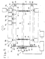
- Fig. 1 shows a machining center 1 and a pallet changer 2.
- the pallet changer 2 has a workstation 20 and a robot 100.
- a flexible manufacturing system (FMS) comprises the pallet changer 2 and the machining center 1.
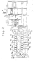
- Fig. 2 shows the machining center 1 in detail.
- the machining center 1 is equipped with a CNC unit 3 and an operation panel 4.
- a spindle 5 of a column 5a can be moved in the Y-direction by operating a servomotor 6.
- the spindle 5 can be rotated by a motor not shown.
- a table 7 is used for mounting a pallet. for a workpiece which will be explained hereinafter.
- the table 7 has a tapered hole 7a. Also, the table 7 can be indexed in the A direction.
- Fig. 3 shows that the table 7 can be moved in the Z direction.
- the table 7 can be indexed in the B direction.
- a plurality of sprockets 8 are provided on an upper portion of the machining center 1.
- a transfer chain 9 and the sprockets 8 are engaged.
- 100 toolholders 10, for example, are detachably attached in the transfer chain 9.
- Each toolholder 10 has a tool 11.
- the machining center 1 is provided with an automatic tool changer 12.
- the automatic tool changer 12 is designed to mount the desired tool holder 10 of the transfer chain 9 in the spindle 5.
- the automatic tool changer 12 is an automatic tool changer as disclosed in Japanese Patent Application No. 61-27892, for example.
- Fig. 2 shows a frame 21 of the workstation 20 equipped with a transfer means 22.
- the transfer means 22 can be operated by a drive means 23 in the feed direction 22X.
- a plurality of pallets PL are detachably arranged in the transfer means 22.
- Each pallet PL is provided with a workpiece (Wl, for example).
- the transfer means 22 can be moved along endless guide rails 24.
- Figs. 2 and 3 show 160 pallets PL each having a workpiece that are mounted in the workstation 20.
- pallets PL are arranged in the first direction of Fig. 3 (Ul direction of Fig. 3 or feed direction 22X of Fig. 2).
- 8 groups of workpieces WG1 to WG8 are arranged in the second direction U2.
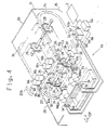
- Fig. 4 shows the transfer means 22 that comprises 20 mounting members 34, two chains 30, 31, supports 33, shafts 26, 27, four sprockets 28, 29 and a multitude of rollers 35.
- the drive means 23 has a servomotor 37, gears 36, 39.
- the guide rails 24, 24 are fixed onto the inside of side walls 25, 25 of the frame 21, respectively.
- the shafts 26, 27 are supported between the side walls 25, 25.
- the two sprockets 28 are attached to the shaft 26 while the two sprockets 29 are attached to the shaft 27.
- the chain 30 is arranged between the sprockets 28 and 29.
- the chain 31 is arranged between the sprockets 28 and 29.
- the chains 30 and 31 are identical in structure. Links 32 of the chain 30 or links 32 of the chain 31 are connected by a pin 32a each other. An end of a support 33 is fixed to each pin 32a.
- the adjacent two supports 33 of the chain 30 are fixed on the lower side of the mounting member 34.
- the adjacent two supports 33 of the chain 31 are fixed on the lower side of the mounting member 34.
- the mounting member 34 has a square-cross section.
- the 20 mounting members 34 are fixed to the chains 30, 31 by means of the supports 33.
- the two rollers 35 are arranged on both sides of the mounting member 34, respectively.
- the rollers 35 are designed to be guided along the guide rails 24, 24.
- Fig. 5 illustrates an end view taken along the M-M line of Fig. 4.
- the shaft 26 is provided with a gear 36.
- the servomotor 37 is secured to the frame 21 and electrically connected to a servo-control unit 37a.
- the servo-control unit 37a is connected to the CNC unit 3 so as to control the servomotor 37 according to the program in the CNC units 3.
- a gear 39 is attached to an output shaft 38 of the servomotor 37.
- the gear 39 and the gear 36 engage each other.
- the eight pallets PL are detachably mounted in each mounting member 34.
- the workpieces Wl to W8 are fixed on the pallets in the exchange position, respectively.
- the rollers 35 are guided along the guide rails 24, respectively.
- Fig. 6 shows the pallets PL and the mounting members 34 in detail.
- the pallet PL comprises a circular plate 40 and a holder 41.
- the holder 41 has a tapered portion 42 and a stud 43.
- the holder 41 has a groove 44.
- An -insert member 45 is provided within the mounting member 34 and has a tapered hole H therein.
- the insert member 45 has springs 47 and balls 48.
- Fig. 4 shows a cleaning unit 50 that comprises a multitude of nozzles 51, a cutting oil reservoir 52 and an air supply means 53.
- the reservoir 52 and nozzles 51 are connected by way of lines 55 while the air supply means 53 and the nozzles 51 are connected by way of lines 56.
- the nozzles 51 face the mounting member 34 which is positioned in the cleaning position CP, corresponding to the side portion of the transfer means 2.
- the mounting member 34 in the side position is remote from the two adjacent mounting members 34.
- the nozzles 51, 51 in pairs correspond to one of the workpieces W153 - W160.
- the reservoir 52 is provided with a pump 52a. It is possible to spray the cutting oil 54 from the nozzles 51 by operating the pump.
- the air supply means 53 is capable of jetting cool air or hot air from the nozzles 51.
- the pump 52a and the air supply means 53 are controlled by the CNC unit 3.
- the robot 100 has a first arm 160, a second arm 161, a moving and positioning means 162 and a tranfer operation means 163.
- Two rails 164, 165 are horizontally fixed on a front wall 21y of the workstation 21.
- a slide table 166 is arranged on the rails 164, 165.
- the moving and positioning means 162 has a servomotor 170, a speed reducer 169, a feed screw 168, a nut 167, the slide table 166 and the rails 164, 165.
- the slide table 166 is provided with a nut 167 which engages with a feed screw 168.
- One end of the feed screw 168 extends to the speed reducer 170.
- the speed reducer 169 is provided with a servomotor 170. By operating the servomotor 170 to rotate the feed screw 168, the slide table 166 can be horizontally moved (the second direction U2).
- the transfer operation means 163 has a cylinder 172, a swing member 173, a rotary circular plate 174, a slide member 175, servomotors 178, 187, 181, 189, a worm gear 188, a nut 185, a feed screw 186, a worm 190 and gears 180, 177.
- the cylinder 172 is equipped within the slide table 166.
- the swing member 173 is rotatably mounted with an end portion thereof on a rod 176 of the cylinder 172.
- the slide member 175 is provided on the rotary circular plate 174.
- the servomotor 178 is attached to the swing member 173.
- An output shaft of the servomotor 178 is provided with the gear 180.
- the gear 177 of the rod 176 and the gear 180 engage each other.
- a shaft 173S of the swing member 173 is rotatably connected to the upper portion of the rod 176.
- the slide member 175 is provided with two servomotors 181. Each servomotor 181 can transmit power by way of gears 182, 183 to a shaft 184.
- the first arm 160 is fixed to the shaft 184. By operating the servomotor 181, the first arm 160 can be rotated at 90° about the shaft 184. Similarly, the second arm 161 can be rotated at 90° about a shaft 184.
- the nut 185 is fixed to a lower side of the slide member 175 and engages the feed screw 186 which can be rotated by the servomotor 187.
- Rails 191 are provided on the rotary circular plate 174.
- the swing member 173 is equipped with the servomotor 189.
- the servomotor 189 has the worm 190 while the worm gear 188 is fixed on a low side of the rotary circular plate 174.
- the worm 190 and the worm gear 188 engage each other.
- the servomotor 181 is connected through a servo-control unit 181a to the CNC unit 3.
- the servomotor 187 is connected through a servo-control unit 187a to the CNC unit 3.
- the servomotor 189 is connected through a servo-control unit 189a to the CNC unit 3.
- the servomotor 170 is connected through a servo-control unit 170a to the CNC unit 3.
- the servomotor 178 is connected through a servo-control unit 178a to the CNC unit 3.
- the cylinder 172 is connected to a hydraulic source 172a which is electrically connected to the CNC unit 5.
- the slide table 166 can be moved in the direction of arrow Zl or Z2 by the servomotor 170.
- the direction of arrow Zl or Z2 is parallel to the second direction U2.
- a rod 176 of the cylinder 172 can be moved in the direction of arrow Yl or Y2.
- the cylinder 172 is preferably a hydraulic cylinder.
- the swing member 173 can be rotated at 180° in the direction Dl or D2 by the servomotor 178.
- the rotary circular plate 174 can be rotated in the direction Gl or G2 by the servomotor 189.
- the slide member 175 can be moved on the swing member 173 in the direction C1 or C2 by operating the servomotor 187 (see Fig. 8).
- the first arm 160 can be rotated in the direction Fl or F2.
- the second arm 161 can be rotated in the direction El or E2.
- Fig. 9 shows the robot 100, the mounting member 34 of the workstation and the table 7 of the machining center.
- the mounting member 34 is in the exchange position EX for the workstation.
- the tapered holes H (Hl, H2, H3, H4) of the mounting member 34 are arranged in the exchange position EX.
- the slide table 166 is in an initial position R.
- the pallet PL is not mounted in the tapered hole 7a of the table 7.
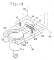
- Fig. 10 shows the first arm 160.
- the first and second arms 160, 161 are identical in
- the first arm 160 has a support 200, and fingers 203, 204.
- the support 200 is rotatably supported on the slide member 175.
- the finger 203 is rotatably supported on the support 200 by means of a bolt 201.
- the finger 204 is rotatably supported on the support 200 by means of a bolt 202.
- Claws 205, 206 are formed in opposed sides of the fingers 203, 204, respectively.
- the claws 205, 206 engage the groove 44 of the holder 41.
- a spring 207 is arranged between the fingers 203, 204.
- a pin 210 is designed to be inserted between rear portions 208, 209.
- the pin 210 is forceably inserted between the rear portions 208, 209 against force of the spring 207 thereby to clamp the holder 41.
- the pin 210 is removed thereby to open the fingers 203, 204 by force of the spring 207.
- the robot, the workstation, the cleaning unit and the machining center can be operated by the program in the CNC unit 3.
- Fig. 2 the drill has already been mounted in the spindle 5 of the machining center 1.
- Fig. 9 the table 7 is positioned in the predetermined position V.
- Figs. 4 and 5 illustrate that by operating the motor 37, the mounting members 34 of the transfer means 22 are moved in the direction 22X.
- the desired mounting member 34 moves up to the exchange position EX.
- the workpieces Wl to W8 are positioned in the exchange position EX.
- Fig. 9 shows the robot 100 positioned in the initial position R.
- the swing member 173 faces the mounting member 34 of the transfer means.
- the slide member 175 is fully moved back in the direction of arrow C2.
- Each of the first and second arms 160, 161 does not hold the pallet PL.
- the rod 176 of Fig. 9 retracts.
- the slide table 166 is moved in the direction of arrow Z2 for positioning the slide table 166 in the position P4. That is, the first arm 160 faces the workpiece W4.
- Fig. 12 shows that the slide member 175 moved in the direction Cl thereby to hold the pallet PL for the workpiece W4 by the first arm 160.
- the rod 176 is moved up in the direction Yl thereby to remove the pallet PL from the tapered hole H4 of the mounting member 34.
- Fig. 13 shows that the first arm 160 is rotated at 90° in the direction F2.
- Fig. 14 shows that the rotary circular plate 174 is rotated at 180° in the direction G2 and then the rod 176 is moved down in the direction Y2.
- Fig. 15 illustrates that the slide table 166 is moved to the position Pl. That is, the second arm 161 faces the pallet PL for the workpiece Wl. The slide member 175 is then moved in the direction Cl thereby to hold the pallet PL by the second arm 161.
- Fig. 16 shows that the rod 176 is moved up in the direction Yl to remove the pallet PL for the workpiece Wl from the tapered hole HI.
- Fig. 17 illustrates that the second arm 161 is rotated at 90° in the direction E2 and then the slide table 166 is moved from the position PI to the initial position R.
- Fig. 18 shows that the swing member 173 is rotated at 180° in the direction Dl.
- Figs. 19 and 20 show the pallet PL for the workpiece Wl in front of the tapered hole 7a of the table 7 in the position V.
- the slide table 166 is moved from the initial position R in the direction Z2 to the tapered hole 7a thereby to insert the pallet PL into the tapered hole 7a.
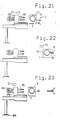
- Fig. 21 shows that the slide table 175 is moved in the direction C2 thereby to remove the pullet PL from the second arm 161.
- the table 7 is moved in the direction X1.
- Fig. 22 shows that the workpiece is moved toward the spindle 5 and drilled by rotating the drill 5a at the predetermined position thereof. After drilling, the table 7 is moved in the direction X2.
- Fig. 23 shows that the slide member 175 is moved in the direction Cl to hold the pallet PL by the second arm 161 again.
- Figs. 24 and 25 show that the slide table 166 is moved in the direction Zl to remove tha pallet PL from the table 7. Accordingly, the slide table 166 returns again to the initial position R. After that, the slide table 175 is moved in the direction C2.
- Fig. 26 hows that the rotary circular plate 174 is rotated at 180° in the direction G2.
- Figs. 27 and 28 show the pallet PL for the workpiece W4 in front of the tapered hole 7a of the table 7.
- the slide table 166 is moved in the direction Z2 to insert the pallet PL into the tapered hole 7a.
- Fig. 29 shows that the slide member 175 is moved in the direction C2 to remove the pallet PL from the first arm 160.
- the table 7 is moved in the direction Xl.
- Fig. 30 shows that the workpiece W4 is moved toward the spindle 5 and drilled the workpiece W4 by the drill 5a. After drilling, the table 7 is moved in the direction X2 to the position V.
- Fig. 31 shows that the slide member 175 is moved in the direction Cl to hold again the pallet PL for the workpiece W4 by the first arm 160.
- Figs. 32 and 33 show that the pallet PL is clamped and moved together with the slide table 166 in the direction Zl to remove the pallet PL from the table 7.
- the swing member 173 is rotated at 180° in the direction G2.
- the slide table 166 is in the initial position R.
- Fig. 34 shows that the slide table 166 is moved from the position R to the position P4.
- the rod 176 is moved down in the direction Y2 to insert the pallet PL into the tapered hole H4.
- Figs. 35 and 36 show that the slide member 175 is moved in the direction C2 to remove the pallet PL from the first arm 160 and then moved from the position P4 to the position Pl.
- the rod 176 is moved up in the direction Yl.
- the rotary circular plate 174 is rotated at 180° in the direction G2.
- Fig. 37 shows that the second arm is rotated at 90° in the direction Fl.
- Fig. 38 shows that the rod 176 is moved down in the direction Y2 to insert the pallet PL for the workpiece Wl into the tapered hole Hl.
- Fig. 39 shows that the slide table 175 is moved in the direction C2 to remove the pallet PL from the second arm 161.
- the pallet PL having the workpiece Wl and the pallet PL having the workpiece W4 can be selected and loaded to perform the machining operations of the workpieces Wl, W4. After that, the pallets PL can be unloaded.
- the machining operations for the workpieces Wl and W4 are explained above. However, of course, the following is conceivable.
- the first arm 160 of the robot faces the pallet PL for the workpiece Wl and then the second arm 161 of the robot faces the pallet PL for the workpiece W2.
- the pallet PL for the workpiece Wl and the pallet PL for the workpiece W2 can be clamped and then loaded to perform machining operations. After that, they can be unloaded.
- the workpieces W3 to W8 can be transferred in sequence.
- the transfer means 22 of the workstation are operated to set a next mounting member 34 in the exchange position EX.
- the machined workpieces Wl to W8 are moved to the cleaning position CP and then cleaned by the clean unit 50 according to the instructions from the program. That is, chips and dust adhered to the machined workpieces Wl to W8 are cleaned by spraying the cutting oil from the nozzles 51 to the machined workpieces Wl to W8. After that, the air supply means 53 jets hot air to the workpieces Wl - W8 through the nozzles 51. Thus, the machined workpieces Wl to W8 can be dried.
- the workpieces and the pallets for the workpieces in the exchange position EX can not be moved in the arrangement direction (the second direction U2).
- the workpieces and the pallets in the exchange position EX may be moved in the alignment direction. That is, the moving direction is parallel to the robot moving direction Zl or Z2.
- This invention is available for a pallet changer for use in a flexible manufacturing system. Pallets each having a workpiece can be efficiently exchanged.
Landscapes
- Engineering & Computer Science (AREA)
- Mechanical Engineering (AREA)
- Feeding Of Workpieces (AREA)
Applications Claiming Priority (3)
| Application Number | Priority Date | Filing Date | Title |
|---|---|---|---|
| JP60032/87 | 1987-03-17 | ||
| JP62060032A JPS63229240A (ja) | 1987-03-17 | 1987-03-17 | パレツトチエンジヤ |
| PCT/JP1988/000251 WO1988006945A1 (fr) | 1987-03-17 | 1988-03-10 | Changeur de palettes |
Publications (3)
| Publication Number | Publication Date |
|---|---|
| EP0351431A1 true EP0351431A1 (de) | 1990-01-24 |
| EP0351431A4 EP0351431A4 (en) | 1992-03-25 |
| EP0351431B1 EP0351431B1 (de) | 1997-10-01 |
Family
ID=13130323
Family Applications (1)
| Application Number | Title | Priority Date | Filing Date |
|---|---|---|---|
| EP88902537A Expired - Lifetime EP0351431B1 (de) | 1987-03-17 | 1988-03-10 | Palettenaustauschvorrichtung |
Country Status (5)
| Country | Link |
|---|---|
| US (1) | US4985971A (de) |
| EP (1) | EP0351431B1 (de) |
| JP (1) | JPS63229240A (de) |
| DE (1) | DE3856036T2 (de) |
| WO (1) | WO1988006945A1 (de) |
Cited By (5)
| Publication number | Priority date | Publication date | Assignee | Title |
|---|---|---|---|---|
| EP0462533A3 (en) * | 1990-06-20 | 1992-12-02 | Matsuura Machinery Corporation | Pallet storage device and pallet exchange device for machine tool, and lathe with pallet automatically removable |
| EP0598978A3 (de) * | 1992-10-29 | 1995-05-24 | Pfu Ltd | Mehrzweckfertigungssystem. |
| EP0707373A3 (de) * | 1994-09-13 | 1999-04-21 | AXIS S.p.A. | Beförderungssystem für dynamoelektrische Maschinen und Lade- und Entladevorrichtung |
| US5967288A (en) * | 1994-09-13 | 1999-10-19 | Axis Usa, Inc. | Method for loading and unloading dynamo-electric machine components |
| EP3332906A1 (de) * | 2016-12-07 | 2018-06-13 | Roland DG Corporation | Bearbeitungszielfördervorrichtung und schneidsystem |
Families Citing this family (9)
| Publication number | Priority date | Publication date | Assignee | Title |
|---|---|---|---|---|
| JPS63318236A (ja) * | 1987-06-19 | 1988-12-27 | Kitamura Mach Co Ltd | パレット交換装置 |
| US5153973A (en) * | 1990-11-01 | 1992-10-13 | Kitamura Machinery Co., Ltd. | Work changer |
| DE9205554U1 (de) * | 1992-04-24 | 1993-08-19 | Schiess-Kopp Werkzeugmaschinen GmbH, 89231 Neu-Ulm | Vorrichtung zur spangebenden Metallbearbeitung |
| IT1262200B (it) * | 1993-09-21 | 1996-06-19 | Danieli Off Mecc | Dispositivo cambio rapido gruppo a cingolo |
| IT1298389B1 (it) * | 1997-12-24 | 2000-01-05 | Giben Impianti Spa | Macchina sezionatrice per il taglio di pannelli e relativo metodo di taglio. |
| DE102009011672A1 (de) * | 2009-01-16 | 2010-07-22 | Wieland Dental + Technik Gmbh & Co. Kg | Bearbeitungsmaschine |
| JP6356008B2 (ja) * | 2014-08-21 | 2018-07-11 | 三菱重工工作機械株式会社 | 部材保持装置および当該部材保持装置を備えた工作機械 |
| DE102018211023A1 (de) * | 2018-07-04 | 2020-01-09 | Deckel Maho Pfronten Gmbh | Palettensystem zum speichern und transportieren von paletten für werkzeugmaschinen |
| EP3769912A1 (de) * | 2019-07-23 | 2021-01-27 | Erst-Maschinenbau GmbH | Werkzeugmaschinen-kokon, werkzeugwechselvorrichtung und werkzeugmaschine |
Family Cites Families (17)
| Publication number | Priority date | Publication date | Assignee | Title |
|---|---|---|---|---|
| US4013176A (en) * | 1970-02-17 | 1977-03-22 | Kearney & Trecker Corporation | Unitary work changer for a machining center |
| DE2060957A1 (de) * | 1970-11-26 | 1972-05-31 | Werkzeugmasch Okt Veb | Speichersystem fuer Werkstuecke und/oder Werkzeuge fuer mehrere Bearbeitungsstationen |
| JPS5411905B2 (de) * | 1973-06-22 | 1979-05-18 | ||
| SE425951B (sv) * | 1978-11-13 | 1982-11-29 | Smt Machine Co Ab | Detaljvexlare vid svarvar |
| JPS5669056A (en) * | 1979-11-08 | 1981-06-10 | Fanuc Ltd | Robot-equipped machining center |
| US4365920A (en) * | 1980-05-21 | 1982-12-28 | Acco Industries, Inc. | Loader-unloader system for workpieces |
| JPS57184647A (en) * | 1981-04-30 | 1982-11-13 | Mitsubishi Heavy Ind Ltd | Device for replacement of workpiece |
| JPS57194862A (en) * | 1981-05-24 | 1982-11-30 | Murata Mach Ltd | Unmanned transfer system to machine tool |
| US4663823A (en) * | 1982-03-10 | 1987-05-12 | Renishaw Plc | Machine tool |
| JPS6176250A (ja) * | 1984-09-24 | 1986-04-18 | Toyoda Mach Works Ltd | ロボツトによる交換システム |
| JPS61244440A (ja) * | 1985-04-19 | 1986-10-30 | Hitachi Seiki Co Ltd | 工作機械のパレツト交換装置 |
| JPS61250243A (ja) * | 1985-04-27 | 1986-11-07 | ナショナル住宅産業株式会社 | 外壁パネルの接合構造 |
| JPS6263033A (ja) * | 1985-09-11 | 1987-03-19 | Kitamura Kikai Kk | 多面加工装置 |
| US4890716A (en) * | 1985-10-15 | 1990-01-02 | Kitamura Machinery Co., Ltd. | Machine tool |
| IT1215192B (it) * | 1986-10-06 | 1990-01-31 | O C N S P A | Centro di lavorazione con magazzino per gli utensili |
| AT387354B (de) * | 1987-02-18 | 1989-01-10 | Heid Ag Maschf | Greifer fuer werkstuecke, spannpaletten, spannmittel od.dgl. |
| DE3720180C1 (de) * | 1987-06-16 | 1988-06-30 | Erowa Ag | Wechselvorrichtung fuer eine Werkzeugmaschine |
-
1987
- 1987-03-17 JP JP62060032A patent/JPS63229240A/ja active Granted
-
1988
- 1988-03-10 WO PCT/JP1988/000251 patent/WO1988006945A1/ja not_active Ceased
- 1988-03-10 US US07/415,256 patent/US4985971A/en not_active Expired - Lifetime
- 1988-03-10 DE DE3856036T patent/DE3856036T2/de not_active Expired - Fee Related
- 1988-03-10 EP EP88902537A patent/EP0351431B1/de not_active Expired - Lifetime
Cited By (6)
| Publication number | Priority date | Publication date | Assignee | Title |
|---|---|---|---|---|
| EP0462533A3 (en) * | 1990-06-20 | 1992-12-02 | Matsuura Machinery Corporation | Pallet storage device and pallet exchange device for machine tool, and lathe with pallet automatically removable |
| EP0598978A3 (de) * | 1992-10-29 | 1995-05-24 | Pfu Ltd | Mehrzweckfertigungssystem. |
| US6105242A (en) * | 1992-10-29 | 2000-08-22 | Fujitsu Limited | Pallet routing system for a versatile production system |
| EP0707373A3 (de) * | 1994-09-13 | 1999-04-21 | AXIS S.p.A. | Beförderungssystem für dynamoelektrische Maschinen und Lade- und Entladevorrichtung |
| US5967288A (en) * | 1994-09-13 | 1999-10-19 | Axis Usa, Inc. | Method for loading and unloading dynamo-electric machine components |
| EP3332906A1 (de) * | 2016-12-07 | 2018-06-13 | Roland DG Corporation | Bearbeitungszielfördervorrichtung und schneidsystem |
Also Published As
| Publication number | Publication date |
|---|---|
| DE3856036D1 (de) | 1997-11-06 |
| JPH0351544B2 (de) | 1991-08-07 |
| EP0351431A4 (en) | 1992-03-25 |
| US4985971A (en) | 1991-01-22 |
| DE3856036T2 (de) | 1998-04-16 |
| WO1988006945A1 (fr) | 1988-09-22 |
| EP0351431B1 (de) | 1997-10-01 |
| JPS63229240A (ja) | 1988-09-26 |
Similar Documents
| Publication | Publication Date | Title |
|---|---|---|
| EP0351431A1 (de) | Palettenaustauschvorrichtung | |
| US5093978A (en) | Manipulator for tools and tool adapters | |
| KR101921227B1 (ko) | 수평형 멀티스핀들 가공센터 | |
| US6626075B2 (en) | Composite NC lathe | |
| EP0088645B1 (de) | Werkzeugmaschine | |
| EP0208125B1 (de) | Automatisches Werkzeugwechselsystem für Werkzeugmaschinen | |
| US7103955B2 (en) | Machining apparatus and machining line provided with same | |
| US10518337B2 (en) | Machine tool for machining a workpiece and spindle carrier assembly for use on such a machine tool | |
| EP3417995B1 (de) | Werkzeugmaschine, insbesondere mehrspindlige drehmaschine | |
| EP2163334B2 (de) | Maschine mit einer Trommel mit Werkstückspindeln, die in der Längsachse der Trommel bewegbar sind | |
| CN101198440A (zh) | 用于灵活加工工件的生产线 | |
| US20180354089A1 (en) | Machine tool for machining a workpiece | |
| EP0366791A1 (de) | Palettenaustauschvorrichtung | |
| GB2229658A (en) | Method and apparatus for processing work pieces | |
| JPH0639032B2 (ja) | 工作物を加工する加工ユニツトで工具支持体を交換するための装置 | |
| JPS62181849A (ja) | 回転工具用ホルダ装置 | |
| JP2760935B2 (ja) | 工作機械のストック用工具交換装置 | |
| KR100321960B1 (ko) | 주축이 이송되는 공작물의 양측가공용 수직 다두선반 | |
| SU1551515A1 (ru) | Гибкий токарный модуль | |
| KR100788835B1 (ko) | 4축 제어 갠트리로더 | |
| US20250353130A1 (en) | Machining centre for the mechanical processing of workpieces | |
| US20260061533A1 (en) | Tool post for machine tools | |
| CN213766553U (zh) | 回转式多刀同步取换装置、刀库装置及多主轴加工机床 | |
| US20070271765A1 (en) | Machining System for Cutting Cylinder Heads | |
| JPH0715246U (ja) | 複数z軸台を有する自動多面加工機 |
Legal Events
| Date | Code | Title | Description |
|---|---|---|---|
| PUAI | Public reference made under article 153(3) epc to a published international application that has entered the european phase |
Free format text: ORIGINAL CODE: 0009012 |
|
| 17P | Request for examination filed |
Effective date: 19890901 |
|
| AK | Designated contracting states |
Kind code of ref document: A1 Designated state(s): CH DE FR GB IT LI NL |
|
| A4 | Supplementary search report drawn up and despatched |
Effective date: 19920131 |
|
| AK | Designated contracting states |
Kind code of ref document: A4 Designated state(s): CH DE FR GB IT LI NL |
|
| 17Q | First examination report despatched |
Effective date: 19931112 |
|
| GRAG | Despatch of communication of intention to grant |
Free format text: ORIGINAL CODE: EPIDOS AGRA |
|
| GRAH | Despatch of communication of intention to grant a patent |
Free format text: ORIGINAL CODE: EPIDOS IGRA |
|
| GRAH | Despatch of communication of intention to grant a patent |
Free format text: ORIGINAL CODE: EPIDOS IGRA |
|
| GRAA | (expected) grant |
Free format text: ORIGINAL CODE: 0009210 |
|
| AK | Designated contracting states |
Kind code of ref document: B1 Designated state(s): CH DE FR GB IT LI NL |
|
| PG25 | Lapsed in a contracting state [announced via postgrant information from national office to epo] |
Ref country code: IT Free format text: LAPSE BECAUSE OF FAILURE TO SUBMIT A TRANSLATION OF THE DESCRIPTION OR TO PAY THE FEE WITHIN THE PRE;WARNING: LAPSES OF ITALIAN PATENTS WITH EFFECTIVE DATE BEFORE 2007 MAY HAVE OCCURRED AT ANY TIME BEFORE 2007. THE CORRECT EFFECTIVE DATE MAY BE DIFFERENT FROM THE ONE RECORDED.SCRIBED TIME-LIMIT Effective date: 19971001 Ref country code: LI Effective date: 19971001 Ref country code: CH Effective date: 19971001 |
|
| REG | Reference to a national code |
Ref country code: CH Ref legal event code: EP |
|
| REF | Corresponds to: |
Ref document number: 3856036 Country of ref document: DE Date of ref document: 19971106 |
|
| ET | Fr: translation filed | ||
| REG | Reference to a national code |
Ref country code: CH Ref legal event code: PL |
|
| PLBE | No opposition filed within time limit |
Free format text: ORIGINAL CODE: 0009261 |
|
| STAA | Information on the status of an ep patent application or granted ep patent |
Free format text: STATUS: NO OPPOSITION FILED WITHIN TIME LIMIT |
|
| 26N | No opposition filed | ||
| PGFP | Annual fee paid to national office [announced via postgrant information from national office to epo] |
Ref country code: DE Payment date: 19990316 Year of fee payment: 12 |
|
| PGFP | Annual fee paid to national office [announced via postgrant information from national office to epo] |
Ref country code: FR Payment date: 19990318 Year of fee payment: 12 |
|
| PGFP | Annual fee paid to national office [announced via postgrant information from national office to epo] |
Ref country code: NL Payment date: 19990322 Year of fee payment: 12 |
|
| PGFP | Annual fee paid to national office [announced via postgrant information from national office to epo] |
Ref country code: GB Payment date: 19990324 Year of fee payment: 12 |
|
| PG25 | Lapsed in a contracting state [announced via postgrant information from national office to epo] |
Ref country code: GB Free format text: LAPSE BECAUSE OF NON-PAYMENT OF DUE FEES Effective date: 20000310 |
|
| PG25 | Lapsed in a contracting state [announced via postgrant information from national office to epo] |
Ref country code: NL Free format text: LAPSE BECAUSE OF NON-PAYMENT OF DUE FEES Effective date: 20001001 |
|
| GBPC | Gb: european patent ceased through non-payment of renewal fee |
Effective date: 20000310 |
|
| PG25 | Lapsed in a contracting state [announced via postgrant information from national office to epo] |
Ref country code: FR Free format text: LAPSE BECAUSE OF NON-PAYMENT OF DUE FEES Effective date: 20001130 |
|
| NLV4 | Nl: lapsed or anulled due to non-payment of the annual fee |
Effective date: 20001001 |
|
| REG | Reference to a national code |
Ref country code: FR Ref legal event code: ST |
|
| PG25 | Lapsed in a contracting state [announced via postgrant information from national office to epo] |
Ref country code: DE Free format text: LAPSE BECAUSE OF NON-PAYMENT OF DUE FEES Effective date: 20010103 |