EP0351451A2 - Circuit de réglage d'un courant pulsatoire - Google Patents
Circuit de réglage d'un courant pulsatoire Download PDFInfo
- Publication number
- EP0351451A2 EP0351451A2 EP88118381A EP88118381A EP0351451A2 EP 0351451 A2 EP0351451 A2 EP 0351451A2 EP 88118381 A EP88118381 A EP 88118381A EP 88118381 A EP88118381 A EP 88118381A EP 0351451 A2 EP0351451 A2 EP 0351451A2
- Authority
- EP
- European Patent Office
- Prior art keywords
- current
- voltage
- circuit arrangement
- output
- pulse width
- Prior art date
- Legal status (The legal status is an assumption and is not a legal conclusion. Google has not performed a legal analysis and makes no representation as to the accuracy of the status listed.)
- Withdrawn
Links
Images
Classifications
-
- H—ELECTRICITY
- H01—ELECTRIC ELEMENTS
- H01H—ELECTRIC SWITCHES; RELAYS; SELECTORS; EMERGENCY PROTECTIVE DEVICES
- H01H47/00—Circuit arrangements not adapted to a particular application of the relay and designed to obtain desired operating characteristics or to provide energising current
- H01H47/22—Circuit arrangements not adapted to a particular application of the relay and designed to obtain desired operating characteristics or to provide energising current for supplying energising current for relay coil
- H01H47/32—Energising current supplied by semiconductor device
- H01H47/325—Energising current supplied by semiconductor device by switching regulator
Definitions
- the invention relates to a circuit arrangement for regulating a pulsating current through an inductor, in particular the coil of an electro-magnetic valve, the inductor being connected in series with a semiconductor switch and in parallel with a free-wheeling diode, and furthermore a setpoint voltage can be fed to a controller whose output is connected to a control input of the semiconductor switch via a pulse width modulator.
- the object of the present invention is to provide a circuit arrangement for regulating a pulsating current through an inductor, in which the coil current is inferred from the temporal part of the current flow, namely the time in which the current flows through the semiconductor switch, during the entire period can.
- the circuit arrangement according to the invention is characterized in that the current which can be measured when the semiconductor switch is conducting is time-weighted and integrated.
- a further development of the invention consists in that an actual value voltage can be derived with the aid of a current / voltage converter which is connected in series with the inductance and the semiconductor switch, a further switch which can be controlled by the pulse width modulator and an integrator.
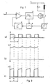
- a coil 1 is connected in series with a transistor 2 and a current / voltage converter 3 between the positive pole 4 of an operating voltage source (not shown in detail) and ground potential.
- the coil 1 is part of an electromagnetic valve, in particular a valve for fuel injection in an internal combustion engine.
- the coil 1 is connected to a freewheeling diode 5 in parallel.
- a voltage Usoll is supplied as a setpoint to a controller 7 via an input 6.
- the output of the controller 7 is connected to the input of a pulse width modulator 8, the output of which is connected to the control electrode of the transistor 2.
- the pulse width modulator 8 controls a switch 9, which can be formed, for example, by a field effect transistor.
- the current / voltage converter 3 consists of a resistor, across which a voltage proportional to the current drops. This is fed via switch 9 to an integrator 10, the output of which is connected to the inverting input of controller 7.
- integrator 10 Various known circuits are suitable as integrator 10, for example a so-called Miller integrator.
- the integration time constant is significantly longer than the period of the signal emitted by the pulse width modulator.
- the controller 7 is shown for the sake of simplicity as a differential amplifier. However, various types of controllers such as PI controllers can be used within the scope of the invention.
- FIG. 2a shows the course of the output voltage of the pulse width modulator, the time shift of the trailing edge dependent on the output voltage of the controller being indicated by a double arrow.
- the transistor 2 is conductive during the period t0 to t1. During the remaining part of the period T, the transistor 2 is blocked.
- the current is shown in FIG. 2b) through the coil 1 increases during the time t0 to t1 and then drops again until the transistor 2 is switched on again.
- a current i1 flows through the transistor 2 during the period t0 to t1.
- the current i2 flows through the free-wheeling diode 5 during the period t1 until the end of the period T.
- 2c) shows the time profile of the current i1 through the transistor, which can be detected with the aid of the current / voltage converter 3.
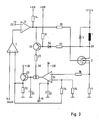
- the pulse width modulator is formed by a differential amplifier 12, one input 13 of which is a sawtooth-shaped signal and the other input of which is the output voltage of the regulator 7.
- the output of the differential amplifier 12 is connected via a resistor 14 to + UB and via a further resistor 15 to the control electrode of the transistor 2.
- the voltage UB is stabilized and is, for example, + 5V.
- OTA Operational Transductance Amplifier
- the OTA 17 is controlled via a transistor 26, the emitter of which is connected to the output of the differential amplifier 12 and the collector of which is connected to the control input 28 of the OTA 17 via a resistor 27.
- the transistor 26 is in turn controlled in that the voltage at the connection point 29 between the coil 1 and the transistor 2 is supplied to the base of the transistor 26 via a voltage divider 30, 31.
- a diode 32 is provided, which protects the base of transistor 26 from overvoltages.
- the illustrated control of the OTA 17 has the effect that the OTA 17 only delivers an output current when the transistor 2 and thus also the transistor 26 are conductive.
- the integrator is active during this time. During the remaining part of the period of the output signals of the pulse width modulator, the output of the OTA 17 is blocked, so that the output voltage of the integrator does not change.
Landscapes
- Engineering & Computer Science (AREA)
- Power Engineering (AREA)
- Dc-Dc Converters (AREA)
- Magnetically Actuated Valves (AREA)
Applications Claiming Priority (2)
| Application Number | Priority Date | Filing Date | Title |
|---|---|---|---|
| DE19883824526 DE3824526A1 (de) | 1988-07-20 | 1988-07-20 | Schaltungsanordnung zur regelung eines pulsierenden stroms |
| DE3824526 | 1988-07-20 |
Publications (2)
| Publication Number | Publication Date |
|---|---|
| EP0351451A2 true EP0351451A2 (fr) | 1990-01-24 |
| EP0351451A3 EP0351451A3 (fr) | 1990-11-22 |
Family
ID=6359070
Family Applications (1)
| Application Number | Title | Priority Date | Filing Date |
|---|---|---|---|
| EP19880118381 Withdrawn EP0351451A3 (fr) | 1988-07-20 | 1988-11-04 | Circuit de réglage d'un courant pulsatoire |
Country Status (3)
| Country | Link |
|---|---|
| US (1) | US4978865A (fr) |
| EP (1) | EP0351451A3 (fr) |
| DE (1) | DE3824526A1 (fr) |
Cited By (4)
| Publication number | Priority date | Publication date | Assignee | Title |
|---|---|---|---|---|
| DE4117535A1 (de) * | 1991-05-29 | 1992-12-03 | Miele & Cie | Schaltungsanordnung zum ansteuern eines relais |
| DE9409760U1 (de) * | 1993-06-25 | 1994-09-01 | Siemens AG, 80333 München | Schaltungsanordnung zur Ansteuerung eines Schützes |
| DE9409759U1 (de) * | 1993-06-25 | 1994-10-27 | Siemens AG, 80333 München | Schaltungsanordnung zur Realisierung eines konstanten Schütz-Haltestroms |
| WO1998013847A1 (fr) * | 1996-09-24 | 1998-04-02 | Siemens Aktiengesellschaft | Circuit d'alimentation en energie d'un mecanisme a commande electromagnetique d'un appareil de commutation |
Families Citing this family (39)
| Publication number | Priority date | Publication date | Assignee | Title |
|---|---|---|---|---|
| DE3805031C2 (de) * | 1988-02-18 | 1997-04-17 | Bosch Gmbh Robert | Vorrichtung zur Ansteuerung eines elektromagnetischen Verbrauchers |
| JPH03164912A (ja) * | 1989-11-24 | 1991-07-16 | Mitsubishi Electric Corp | デューティソレノイドバルブの駆動装置 |
| DE4011217A1 (de) * | 1990-04-06 | 1991-10-10 | Lucas Ind Plc | Verfahren zum ansteuern eines magnetventils einer schlupf-regelanlage |
| DE4026427C1 (fr) * | 1990-08-21 | 1992-02-13 | Siemens Ag, 8000 Muenchen, De | |
| JP3030076B2 (ja) * | 1990-11-01 | 2000-04-10 | 三菱電機株式会社 | 電流制御回路 |
| US5087866A (en) * | 1991-05-22 | 1992-02-11 | Lucas Industries | Temperature compensating circuit for LVDT and control system |
| US5255152A (en) * | 1991-08-21 | 1993-10-19 | Eaton Corporation | Controller for fixed-time pull-in of a relay |
| US5245261A (en) * | 1991-10-24 | 1993-09-14 | International Business Machines Corporation | Temperature compensated overcurrent and undercurrent detector |
| US5237262A (en) * | 1991-10-24 | 1993-08-17 | International Business Machines Corporation | Temperature compensated circuit for controlling load current |
| US5543632A (en) * | 1991-10-24 | 1996-08-06 | International Business Machines Corporation | Temperature monitoring pilot transistor |
| DE4201652C2 (de) * | 1992-01-22 | 1997-11-06 | Rexroth Mannesmann Gmbh | Proportionalventil mit Ansteuerschaltung und Netzspannungsbetrieb |
| US5450270A (en) * | 1992-12-09 | 1995-09-12 | Jatco Corporation | Solenoid valve control system |
| TW241370B (fr) * | 1992-12-15 | 1995-02-21 | Fuji Electrical Machinery Co Ltd | |
| DE4341797A1 (de) * | 1993-12-08 | 1995-06-14 | Bosch Gmbh Robert | Verfahren und Vorrichtung zur Ansteuerung eines elektromagnetischen Verbrauchers |
| JP3134724B2 (ja) * | 1995-02-15 | 2001-02-13 | トヨタ自動車株式会社 | 内燃機関の弁駆動装置 |
| FR2734394A1 (fr) * | 1995-05-17 | 1996-11-22 | Caterpillar Inc | Commande d'amplitude de tremblement |
| US5621603A (en) * | 1995-07-26 | 1997-04-15 | United Technologies Corporation | Pulse width modulated solenoid driver controller |
| DE19623442A1 (de) * | 1996-06-12 | 1998-01-02 | Telefunken Microelectron | Vorrichtung zum Ermitteln des in einer Induktivität fließenden Stroms |
| WO1998024008A1 (fr) * | 1996-11-22 | 1998-06-04 | Temic Telefunken Microelectronic Gmbh | Circuit de reglage comprenant un regulateur numerique pour reguler le courant d'entree d'un acteur electrique a l'aide de la modulation d'impulsions en largeur |
| US5815362A (en) * | 1996-12-04 | 1998-09-29 | Westinghouse Air Brake Company | Pulse width modulated drive for an infinitely variable solenoid operated brake cylinder pressure control valve |
| DE19706247B4 (de) * | 1997-02-18 | 2005-05-19 | Burgert, Markus | Schaltungsanordnung zur Steuerung von Elektromagneten und Regelung des Spulenstroms |
| US6208497B1 (en) | 1997-06-26 | 2001-03-27 | Venture Scientifics, Llc | System and method for servo control of nonlinear electromagnetic actuators |
| US6942469B2 (en) | 1997-06-26 | 2005-09-13 | Crystal Investments, Inc. | Solenoid cassette pump with servo controlled volume detection |
| DE29715925U1 (de) | 1997-09-05 | 1997-10-23 | Festo AG & Co, 73734 Esslingen | Schaltungsvorrichtung |
| US5818678A (en) * | 1997-10-09 | 1998-10-06 | Delco Electronics Corporation | Tri-state control apparatus for a solenoid having on off and PWM control modes |
| DE19756461A1 (de) * | 1997-12-18 | 1999-07-01 | Bosch Gmbh Robert | Verfahren zum Beeinflussen der elektrischen Leistung einer Last mit einem impulsbreitenmodulierten Signal |
| US6982323B1 (en) * | 1997-12-23 | 2006-01-03 | Alexion Pharmaceuticals, Inc. | Chimeric proteins for diagnosis and treatment of diabetes |
| JP4118414B2 (ja) * | 1998-10-29 | 2008-07-16 | サンデン株式会社 | 可変容量圧縮機の容量制御弁の制御回路 |
| DE19915593A1 (de) * | 1999-04-07 | 2000-11-16 | Daimler Chrysler Ag | Schaltungsanordnung zur Bestimmung des Stroms durch ein induktives Bauteil |
| US6493204B1 (en) | 1999-07-09 | 2002-12-10 | Kelsey-Hayes Company | Modulated voltage for a solenoid valve |
| US7315440B1 (en) | 2003-12-09 | 2008-01-01 | Yazaki North America, Inc. | Circuit and method for driving a coil-armature device |
| DE10358858A1 (de) * | 2003-12-16 | 2005-07-14 | Robert Bosch Gmbh | Verfahren und Vorrichtung zum Betreiben einer induktiven Last mit unterschiedlichen elektrischen Spannungen |
| FR2899718B1 (fr) * | 2006-04-11 | 2008-05-23 | Crouzet Automatismes Soc Par A | Dispositif de detection d'arc electrique, dispositif de coupure comportant un tel dispositif et procede de detection d'arc electrique |
| DE102006058879A1 (de) * | 2006-12-13 | 2008-06-26 | Siemens Ag | Messvorrichtung zur Messung eines elektrischen Stromes |
| DE102008055696A1 (de) | 2008-01-25 | 2009-07-30 | Continental Teves Ag & Co. Ohg | Elektronische Schaltungseinrichtung zur Erfassung eines Detektionselementstroms und/oder einer Temperatur in diesem Detektionselement |
| GB2470211B (en) * | 2009-05-14 | 2013-07-31 | Gm Global Tech Operations Inc | Hysteresis-type electronic controlling device for fuel injectors and associated method |
| US8786138B2 (en) * | 2010-05-21 | 2014-07-22 | General Electric Company | Systems, methods, and apparatus for controlling actuator drive current using bi-directional hysteresis control |
| FR2971102B1 (fr) * | 2011-02-01 | 2019-09-06 | Safran Landing Systems | Procede de limitation d'un courant fourni par une source d'alimentation en courant continu. |
| CN102426984B (zh) * | 2011-11-29 | 2013-12-04 | 福州大学 | 抗晃电智能交流接触器高频控制系统 |
Family Cites Families (9)
| Publication number | Priority date | Publication date | Assignee | Title |
|---|---|---|---|---|
| JPS56151261A (en) * | 1980-04-24 | 1981-11-24 | Japan Electronic Control Syst Co Ltd | Operating device for fuel injection valve |
| JPS57121703A (en) * | 1981-01-22 | 1982-07-29 | Nippon Denso Co Ltd | Driving circuit of electromagnetic operating device |
| DE3135805A1 (de) * | 1981-09-10 | 1983-03-24 | Robert Bosch Gmbh, 7000 Stuttgart | Elektrische schaltungsanordnung in verbindung mit einem kfz-steuergeraet |
| JPS5851233A (ja) * | 1981-09-21 | 1983-03-25 | Hitachi Ltd | 燃料噴射弁駆動回路 |
| US4556926A (en) * | 1982-09-27 | 1985-12-03 | Ricoh Company, Ltd. | Electromagnet driving circuit |
| DE3515039C2 (de) * | 1985-04-25 | 1987-04-02 | Klöckner, Wolfgang, Dr., 8033 Krailling | Schaltung für ein elektromagnetisch betätigtes Gaswechselventil einer Brennkraftmaschine |
| ES8703213A1 (es) * | 1985-04-25 | 1987-02-16 | Kloeckner Wolfgang Dr | Procedimiento para el accionamiento de una maquina motriz de combustion interna |
| US4661766A (en) * | 1985-12-23 | 1987-04-28 | Caterpillar Inc. | Dual current sensing driver circuit |
| GB8616965D0 (en) * | 1986-07-11 | 1986-08-20 | Lucas Ind Plc | Drive circuit |
-
1988
- 1988-07-20 DE DE19883824526 patent/DE3824526A1/de not_active Withdrawn
- 1988-11-04 EP EP19880118381 patent/EP0351451A3/fr not_active Withdrawn
-
1989
- 1989-04-20 US US07/341,147 patent/US4978865A/en not_active Expired - Fee Related
Cited By (4)
| Publication number | Priority date | Publication date | Assignee | Title |
|---|---|---|---|---|
| DE4117535A1 (de) * | 1991-05-29 | 1992-12-03 | Miele & Cie | Schaltungsanordnung zum ansteuern eines relais |
| DE9409760U1 (de) * | 1993-06-25 | 1994-09-01 | Siemens AG, 80333 München | Schaltungsanordnung zur Ansteuerung eines Schützes |
| DE9409759U1 (de) * | 1993-06-25 | 1994-10-27 | Siemens AG, 80333 München | Schaltungsanordnung zur Realisierung eines konstanten Schütz-Haltestroms |
| WO1998013847A1 (fr) * | 1996-09-24 | 1998-04-02 | Siemens Aktiengesellschaft | Circuit d'alimentation en energie d'un mecanisme a commande electromagnetique d'un appareil de commutation |
Also Published As
| Publication number | Publication date |
|---|---|
| EP0351451A3 (fr) | 1990-11-22 |
| DE3824526A1 (de) | 1990-01-25 |
| US4978865A (en) | 1990-12-18 |
Similar Documents
| Publication | Publication Date | Title |
|---|---|---|
| EP0351451A2 (fr) | Circuit de réglage d'un courant pulsatoire | |
| DE3708892A1 (de) | Strommesseinrichtung, insbesondere zur bestimmung des motorstroms eines gleichstrommotors | |
| DE3507103A1 (de) | Treiberstromkreis fuer eine magnetspule | |
| DE2745294A1 (de) | Schwellenschaltung fuer ein elektronisches zuendsystem | |
| DE3219815C2 (fr) | ||
| DE2061943C3 (de) | Differenzverstärker | |
| EP0280261A2 (fr) | Circuit pour la production d'un signal carré indépendant de la température à une grandeur mesurée | |
| DE3626088C2 (fr) | ||
| DE3710871A1 (de) | Schaltung zur formung einer messsignalspannung in ein rechtecksignal | |
| DE102022101876B4 (de) | Magnetkern für Stromsensoren | |
| DE1142902B (de) | Impulsbreitenmodulator mit zwei Transistoren | |
| DE3212942C2 (fr) | ||
| EP0432280A1 (fr) | Interface entre deux circuits électriques fonctionnant sous des tensions d'alimentation différentes | |
| DE4336726A1 (de) | Schaltung zur Strommessung | |
| DE3303945A1 (de) | Schaltung zur temperaturkompensierenden stromversorgung eines hallgenerators | |
| DE3034023C2 (fr) | ||
| DE3405599A1 (de) | Stromfuehler fuer den regelkreis eines schaltreglers | |
| EP0576700B1 (fr) | Prothèse auditive | |
| EP0217147A1 (fr) | Disposition de circuit pour alimenter en signaux un appareil de mesure à aimant rotatif | |
| DE2100929A1 (de) | Steuerschaltung zur Versorgung eines induktiven Verbrauchers | |
| EP0279352A2 (fr) | Circuit d'amplification et de façonnage d'un signal de tension alternative | |
| DE2608266C3 (de) | Schaltungsanordnung zum Ableiten einer kontinuierlich veränderbaren Gleichspannung aus der konstanten Gleichspannung einer Gleichspannungsquelle | |
| DE3051217C2 (en) | IC engine electronic ignition circuit | |
| DE3207147A1 (de) | Gleichstrommessung mit geringem spannungsabfall | |
| WO2002014879A1 (fr) | Circuit destine a detecter un courant traversant un consommateur |
Legal Events
| Date | Code | Title | Description |
|---|---|---|---|
| PUAI | Public reference made under article 153(3) epc to a published international application that has entered the european phase |
Free format text: ORIGINAL CODE: 0009012 |
|
| AK | Designated contracting states |
Kind code of ref document: A2 Designated state(s): DE FR GB IT |
|
| PUAL | Search report despatched |
Free format text: ORIGINAL CODE: 0009013 |
|
| AK | Designated contracting states |
Kind code of ref document: A3 Designated state(s): DE FR GB IT |
|
| STAA | Information on the status of an ep patent application or granted ep patent |
Free format text: STATUS: THE APPLICATION IS DEEMED TO BE WITHDRAWN |
|
| 18D | Application deemed to be withdrawn |
Effective date: 19910514 |