EP0351495A1 - Procédé pour couler des métaux, en particulier de l'acier hors d'une poche de coulée - Google Patents
Procédé pour couler des métaux, en particulier de l'acier hors d'une poche de coulée Download PDFInfo
- Publication number
- EP0351495A1 EP0351495A1 EP89106194A EP89106194A EP0351495A1 EP 0351495 A1 EP0351495 A1 EP 0351495A1 EP 89106194 A EP89106194 A EP 89106194A EP 89106194 A EP89106194 A EP 89106194A EP 0351495 A1 EP0351495 A1 EP 0351495A1
- Authority
- EP
- European Patent Office
- Prior art keywords
- closure
- signal
- open
- ladle
- determined
- Prior art date
- Legal status (The legal status is an assumption and is not a legal conclusion. Google has not performed a legal analysis and makes no representation as to the accuracy of the status listed.)
- Granted
Links
- 238000000034 method Methods 0.000 title claims abstract description 21
- 238000005266 casting Methods 0.000 title claims abstract description 6
- 229910000831 Steel Inorganic materials 0.000 title abstract description 5
- 239000010959 steel Substances 0.000 title abstract description 5
- 239000002184 metal Substances 0.000 title abstract 4
- 230000001105 regulatory effect Effects 0.000 claims abstract description 3
- 230000001960 triggered effect Effects 0.000 claims description 8
- 230000003321 amplification Effects 0.000 claims description 6
- 239000000155 melt Substances 0.000 claims description 6
- 238000003199 nucleic acid amplification method Methods 0.000 claims description 6
- 230000006978 adaptation Effects 0.000 claims description 3
- 238000009826 distribution Methods 0.000 claims description 2
- 239000000161 steel melt Substances 0.000 claims description 2
- 230000033001 locomotion Effects 0.000 abstract description 4
- 238000001514 detection method Methods 0.000 description 12
- 238000009749 continuous casting Methods 0.000 description 5
- 238000010276 construction Methods 0.000 description 3
- 238000009434 installation Methods 0.000 description 3
- 238000013459 approach Methods 0.000 description 2
- 238000006073 displacement reaction Methods 0.000 description 2
- 239000012530 fluid Substances 0.000 description 2
- 230000008014 freezing Effects 0.000 description 2
- 238000007710 freezing Methods 0.000 description 2
- 238000002360 preparation method Methods 0.000 description 2
- 238000012545 processing Methods 0.000 description 2
- 238000005303 weighing Methods 0.000 description 2
- 230000004913 activation Effects 0.000 description 1
- 238000006243 chemical reaction Methods 0.000 description 1
- 238000007796 conventional method Methods 0.000 description 1
- 238000011157 data evaluation Methods 0.000 description 1
- 238000013461 design Methods 0.000 description 1
- 238000011156 evaluation Methods 0.000 description 1
- 238000001914 filtration Methods 0.000 description 1
- 238000007654 immersion Methods 0.000 description 1
- 238000009533 lab test Methods 0.000 description 1
Images
Classifications
-
- B—PERFORMING OPERATIONS; TRANSPORTING
- B22—CASTING; POWDER METALLURGY
- B22D—CASTING OF METALS; CASTING OF OTHER SUBSTANCES BY THE SAME PROCESSES OR DEVICES
- B22D11/00—Continuous casting of metals, i.e. casting in indefinite lengths
- B22D11/16—Controlling or regulating processes or operations
- B22D11/18—Controlling or regulating processes or operations for pouring
- B22D11/181—Controlling or regulating processes or operations for pouring responsive to molten metal level or slag level
-
- B—PERFORMING OPERATIONS; TRANSPORTING
- B22—CASTING; POWDER METALLURGY
- B22D—CASTING OF METALS; CASTING OF OTHER SUBSTANCES BY THE SAME PROCESSES OR DEVICES
- B22D37/00—Controlling or regulating the pouring of molten metal from a casting melt-holding vessel
Definitions
- the present invention relates to a method for casting a metallic melt, in particular steel melt, from a ladle into an intermediate vessel by means of a throttling slide or stopper closure, by means of which the ferrostatic height of the melt is regulated in adaptation to a set withdrawal speed of the cast strand.
- a slide or stopper closure As a control element for the amount of melt flowing out per unit of time.
- the closure normally works in a variable throttling position, i.e. in a position throttled over half of the possible full flow cross-section, in order to be able to follow the opening and closing instructions or signals which, with automatic control of the flow rate from the ladle, taking into account one take-off speed of the strand which is as constant as possible is based on an electronic data evaluation device.
- a constant strand withdrawal speed is primarily ensured by maintaining a substantially constant ferrostatic height in the tundish.
- the present invention has for its object to provide a method of the type mentioned, with which the disadvantages of the conventional systems are avoided, i. H. with which the ferrostatic height in the tundish can be kept largely constant with little effort, with the result of a correspondingly constant strand withdrawal speed.
- Mechanical, hydraulic and / or pneumatic tolerances in the system should have no influence on keeping the ferrostatic height constant.
- the system In combination with the measures of claim 3, the system also approaches the optimal opening position of the ladle closure. In both cases, the tendency of the level change or change in the ferrostatic level in the tundish is determined and taken into account when determining the control signal for the ladle closure.
- the essence of the method according to the invention thus lies in the trend detection described, which can be weight-related, ie based on the weight of the melt in the intermediate vessel, or level-related, ie based on the bath level in the intermediate vessel. Laboratory tests have shown that the weight tolerance can be reduced to ⁇ 50 kg with the method according to the invention; the tolerance of the ferrostatic height in the tundish is reduced accordingly.
- the take-off speed of the strand can be kept very constant, regardless of the sometimes considerable mechanical tolerances in the ladle closure system and without complex displacement sensors and servo and / or proportional valves and without complex preparation of the hydraulic control fluid when using hydraulically controlled Pouring closures.
- the inertia of the control system plays no disadvantage due to the tendency detection according to the invention Roll more.
- the system-inherent tolerances for signal or manipulated variable reversal are added up and thus compensated.
- a signal clock counter is also provided, by means of which it is determined how often the same actuating signal, namely either an open or closed signal, is triggered in succession, the actuating variable after a predetermined number of open or closed signals Is disproportionately reinforced with appropriate compensation of an excessive mechanical play in the slide or stopper closure and its drive.
- This problem occurs in particular when there are leaks or leaks in the hydraulic system. In this way, these can be determined and compensated for.
- amplification factors of different sizes are selected for the opposite control signals, whereby the different control volumes on the piston rod side on the one hand and piston rod-free side on the other hand of a hydraulic actuating cylinder for the pouring closure are to be taken into account.
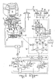
- an intermediate vessel 1 designed as a distribution channel and support rollers 25 for four strands 4 is shown schematically.
- the intermediate vessel 1 has four bottom openings 26 on which either a slide closure 3 or a plug closure 6 are assigned.
- the arrangement can be designed as a so-called "freewheeler".
- the bottom openings 26 of the intermediate vessel 1 are none Slider or stopper closures assigned.
- the ferrostatic height within the intermediate vessel 1 is primarily determined by the degree of opening of the bottom opening of the ladle 24, to which a slide closure 27 is assigned in the embodiment shown.
- the molten steel is introduced from the ladle into the tundish 1 in the usual way via an immersion tube 5.
- the slide closure 27 can also be directly coupled to a piston-cylinder arrangement, as shown in the attached drawing in connection with the slide closure 27 assigned to the ladle 24 as "Alternative I".
- Mechanical tolerances of up to 5 - 10 mm also occur in this construction.
- Plug closures are also characterized by large mechanical tolerances, which are also of the order of up to 30 mm. This is the reason why working in the intermediate vessel with weight tolerances of up to ⁇ 300 kg; accordingly, the tolerances of the ferrostatic height are, and accordingly, it is difficult to maintain a constant peeling speed. This is especially true when the continuous casting system is operated as a so-called "free runner".
- the intermediate vessel 1 in the present case has four weighing cells 2, namely two weighing cells 2 on each end face , assigned, the signals of which are coupled to one another in a load cell measuring circuit 7 and processed into a weight signal corresponding to the weight of the melt in the intermediate vessel 1.
- This is amplified in a measuring amplifier 8, the output signal of which corresponds to the so-called actual weight value "X”.
- the actual weight value is compared in a comparator 9 with a predetermined weight target value "w", in each case at predetermined successive times.
- the corresponding cycle time "Tz" is specified by a time adjuster or clock generator 10.
- a control signal CLOSED is output by the tendency detection. If Tn ⁇ Z1, it is checked whether TN ⁇ Z2. If so, this means that the weight increase in the intermediate vessel 1 takes place too slowly during a time cycle. In this case, the tendency detection emits the control signal OPEN. If TN ⁇ Z2, no control signal is given. Rather, a new determination of the control deviation is triggered (signal 41).
- the mentioned values Z2 is an upper weight trend limit of the mentioned bandwidth. Z1 and Z2 are entered as constant limit values beforehand, expediently in adaptation to the respective continuous casting installation.
- control deviation ⁇ it is first determined whether the actual weight value difference Tn ⁇ 0. If so, a control signal CLOSED is output by the tendency detection 11. If no, it is first checked whether TN> Z1. If this is the case, a control signal OPEN is triggered, if no, it is checked whether TN ⁇ Z2. In the event that TN ⁇ Z2, the tendency detection gives the control signal CLOSED; if no, a new determination of the control deviation is triggered (signal 41).
- the control signals OPEN or CLOSE are proportionally amplified in a controller 12 (gain factor P).
- the corresponding manipulated variable Y OPEN or Y CLOSE is obtained by multiplying the difference between the actual weight value X and the desired weight value w by the gain factor "P", different amplification factors can be selected for the opposite control signals OPEN and CLOSE, e.g. B. for the reasons mentioned at the beginning.
- the manipulated variables Y OPEN and A CLOSE are processed in a so-called signal routing 13 in which the error quantity alpha mentioned above is taken into account due to mechanical or similar tolerances. The procedure is such that when entering the manipulated variable Y OPEN or Y CLOSED it is first checked whether the manipulated variable was Y OPEN or Y CLOSED in the preceding cycle; if yes, the manipulated variable is not changed in signal routing 13.
- the signal output of the signal-ranking 13 may be associated with still clock counter 15, which will determine how often carried out in succession in each case the same control signal or the same manipulated variable Y ON or Y ZU, wherein after a predetermined number of OPEN or CLOSE signals, the corresponding manipulated variable should be disproportionately reinforced.
- the difference between the actual weight value and the desired weight value is then multiplied by a higher amplification factor "P". In this way, e.g. B. an excessive mechanical clearance can be overcome. Furthermore, leaks in the hydraulics for the one or more ladle closures can be compensated in this way.
- the manipulated variable Y OPEN or Y CLOSED correspondingly with regard to their pulse width are then processed in the already mentioned output unit 16 (clock output card).
- automatic mode either the OPEN signal or the CLOSE signal is sent to them together with the corresponding pulse width signal.
- the signals AUTOMATIC OPEN or AUTOMATIC CLOSE are first filtered in a Schmitt trigger 17 (filtering out interference pulses). Then the signals relayed to AND gates via threshold switches 18 and timing elements 19.
- the pulse width signal is input to the timers 19 via an amplifier 21.
- the AND elements release the respective manipulated variable, provided that the AUTOMATIC signal is switched on via the control panel 14.
- a threshold switch 22 and signal amplifier 23 are arranged in front of the AND gates 20. Before the output signals of the AND gates 20 leave the output unit 16, these are amplified by power amplifiers 29 to a size which is sufficient to switch an electromagnetic 4/3-way valve 30 which is in the hydraulic circuit 31 for the hydraulic drive of the above ladle closure.
- the pump and hydraulic tank assigned to the mentioned hydraulic circuit 31 are identified by the reference numbers 32 and 33. In this respect, it is a common arrangement.
- the HAND OPEN and HAND CLOSE signals then reach the 4/3-way valve 30 in the same way as described above.
- a manually operated 4/3-way valve 37 is also arranged which electrically connects one to the control panel 14 Has switch 38. With this switch 38, the 4/3-way valve 30 assigned to the output unit 16 can be blocked, so that the ladle closure can only be controlled via the manually operated 4/3-way valve 37. This is particularly important for emergency circuits.
- the weight tolerances in the intermediate vessel 1 can be reduced to ⁇ 50 kg; Accordingly, the ferrostatic height in the intermediate vessel 1 can be kept constant, with the result that a correspondingly constant take-off speed is ensured. This is particularly important if the system works as a so-called "freewheeler".
- the described method can also be used for slide closures or stopper closures 3 and 5 of an intermediate vessel 1 in relation to the bath level in the associated mold 28.
Landscapes
- Engineering & Computer Science (AREA)
- Mechanical Engineering (AREA)
- Casting Support Devices, Ladles, And Melt Control Thereby (AREA)
- Treatment Of Steel In Its Molten State (AREA)
- Continuous Casting (AREA)
Priority Applications (1)
| Application Number | Priority Date | Filing Date | Title |
|---|---|---|---|
| AT89106194T ATE94441T1 (de) | 1988-05-24 | 1989-04-07 | Verfahren zum vergiessen einer metallischen schmelze, insbesondere stahlschmelze, aus einer giesspfanne. |
Applications Claiming Priority (2)
| Application Number | Priority Date | Filing Date | Title |
|---|---|---|---|
| DE3817580 | 1988-05-24 | ||
| DE3817580A DE3817580A1 (de) | 1988-05-24 | 1988-05-24 | Verfahren zum vergiessen einer metallischen schmelze, insbesondere stahlschmelze, aus einer giesspfanne |
Publications (2)
| Publication Number | Publication Date |
|---|---|
| EP0351495A1 true EP0351495A1 (fr) | 1990-01-24 |
| EP0351495B1 EP0351495B1 (fr) | 1993-09-15 |
Family
ID=6354997
Family Applications (1)
| Application Number | Title | Priority Date | Filing Date |
|---|---|---|---|
| EP89106194A Expired - Lifetime EP0351495B1 (fr) | 1988-05-24 | 1989-04-07 | Procédé pour couler des métaux, en particulier de l'acier hors d'une poche de coulée |
Country Status (3)
| Country | Link |
|---|---|
| EP (1) | EP0351495B1 (fr) |
| AT (1) | ATE94441T1 (fr) |
| DE (2) | DE3817580A1 (fr) |
Cited By (2)
| Publication number | Priority date | Publication date | Assignee | Title |
|---|---|---|---|---|
| WO1993016827A1 (fr) * | 1992-02-20 | 1993-09-02 | British Steel Plc | Procede et dispositif pour couler le metal en fusion |
| CN115740384A (zh) * | 2022-12-15 | 2023-03-07 | 新余钢铁股份有限公司 | 连铸炉号追踪方法 |
Families Citing this family (1)
| Publication number | Priority date | Publication date | Assignee | Title |
|---|---|---|---|---|
| DE3917403C2 (de) * | 1989-05-29 | 1998-02-05 | Zimmermann & Jansen Gmbh | Verfahren und Vorrichtung zum Füllen einer Stranggießkokille mit metallischer Schmelze |
Citations (2)
| Publication number | Priority date | Publication date | Assignee | Title |
|---|---|---|---|---|
| DE2000963A1 (de) * | 1970-01-10 | 1971-07-22 | Kreidler S Metall U Drahtwerke | Verfahren und Einrichtung zum automatischen schrittweisen Regeln des Schmelzenausflusses aus einer Stopfenpfanne od.dgl. zur Speisung einer Stranggiesskokille |
| DE3211787A1 (de) * | 1981-03-30 | 1983-02-03 | Zimmermann & Jansen GmbH, 5160 Düren | Verfahren zur steuerung von ausgussschiebern von giessgefaessen fuer metallurgische abguesse und fuer ein derartiges verfahren verwendbare einrichtung zur exakten stellungsrueckmeldung eines arbeitskolbens |
Family Cites Families (1)
| Publication number | Priority date | Publication date | Assignee | Title |
|---|---|---|---|---|
| US4597048A (en) * | 1983-09-07 | 1986-06-24 | United States Steel Corporation | Digital flow regulation of liquid-level control for a continuous casting mold |
-
1988
- 1988-05-24 DE DE3817580A patent/DE3817580A1/de not_active Withdrawn
-
1989
- 1989-04-07 DE DE89106194T patent/DE58905597D1/de not_active Expired - Fee Related
- 1989-04-07 AT AT89106194T patent/ATE94441T1/de not_active IP Right Cessation
- 1989-04-07 EP EP89106194A patent/EP0351495B1/fr not_active Expired - Lifetime
Patent Citations (2)
| Publication number | Priority date | Publication date | Assignee | Title |
|---|---|---|---|---|
| DE2000963A1 (de) * | 1970-01-10 | 1971-07-22 | Kreidler S Metall U Drahtwerke | Verfahren und Einrichtung zum automatischen schrittweisen Regeln des Schmelzenausflusses aus einer Stopfenpfanne od.dgl. zur Speisung einer Stranggiesskokille |
| DE3211787A1 (de) * | 1981-03-30 | 1983-02-03 | Zimmermann & Jansen GmbH, 5160 Düren | Verfahren zur steuerung von ausgussschiebern von giessgefaessen fuer metallurgische abguesse und fuer ein derartiges verfahren verwendbare einrichtung zur exakten stellungsrueckmeldung eines arbeitskolbens |
Non-Patent Citations (3)
| Title |
|---|
| PATENT ABSTRACTS OF JAPAN, Band 11, Nr. 392 (M-653)[2839], 22. Dezember 1987; & JP-A-62 158 557 (KUROSAKI REFRACT CO. LTD) 14-07-1987 * |
| PATENT ABSTRACTS OF JAPAN, Band 11, Nr. 393 (M-654)[2840], 23. Dezember 1987; & JP-A-62 161 448 (NIPPON KOKAN K.K.) 17-07-1987 * |
| PATENT ABSTRACTS OF JAPAN, Band 9, Nr. 60 (M-364)[1783], 16. März 1985; & JP-A-59 193 746 (UCHIDA YUATSU KIKI K.K.) 02-11-1984 * |
Cited By (3)
| Publication number | Priority date | Publication date | Assignee | Title |
|---|---|---|---|---|
| WO1993016827A1 (fr) * | 1992-02-20 | 1993-09-02 | British Steel Plc | Procede et dispositif pour couler le metal en fusion |
| US5591371A (en) * | 1992-02-20 | 1997-01-07 | British Steel Plc | Method and device for pouring molten metal |
| CN115740384A (zh) * | 2022-12-15 | 2023-03-07 | 新余钢铁股份有限公司 | 连铸炉号追踪方法 |
Also Published As
| Publication number | Publication date |
|---|---|
| ATE94441T1 (de) | 1993-10-15 |
| DE3817580A1 (de) | 1989-11-30 |
| DE58905597D1 (de) | 1993-10-21 |
| EP0351495B1 (fr) | 1993-09-15 |
Similar Documents
| Publication | Publication Date | Title |
|---|---|---|
| EP0223078B1 (fr) | Procédé de démarrage d'une installation de coulée continue à plusieurs lignes | |
| DE3509932C2 (fr) | ||
| AT391643B (de) | Verfahren zum angiessen metallischer schmelze in mehrere stranggiesskokillen und vorrichtung zur durchfuehrung desselben | |
| DE2826060C3 (de) | Verfahren und Einrichtung zur Regelung einer NiederdruckgieSanlage | |
| EP0444297B1 (fr) | Procédé pour démarrer automatiquement une installation de coulée continue | |
| DE2851256C2 (fr) | ||
| DE3020076C2 (de) | Regelvorrichtung für eine automatische Gießanlage | |
| DE102005010838A1 (de) | Gießform, Vorrichtung und Verfahren zum Vergießen von Metallschmelze | |
| EP2376243B1 (fr) | Dispositif de détection du débit, et procédé correspondant | |
| DE2926863C2 (de) | Verfahren zur Steuerung des Ausgußschiebers eines Gießgefäßes | |
| DE69317068T2 (de) | Vorrichtung zur Regelung der Kokillenoszillation bei einer Stranggiesskokille | |
| EP0351495B1 (fr) | Procédé pour couler des métaux, en particulier de l'acier hors d'une poche de coulée | |
| DE3221708C1 (de) | Verfahren und Vorrichtung zum Füllen einer Stranggießkokille beim Angießen eines Stranges | |
| DE2451645A1 (de) | Verfahren und vorrichtung zum vergiessen von metallschmelze in ein aufnahmegefaess | |
| EP0123138B1 (fr) | Procédé et dispositif de commande d'une installation de coulée continue | |
| DE3917403C2 (de) | Verfahren und Vorrichtung zum Füllen einer Stranggießkokille mit metallischer Schmelze | |
| EP0274516B1 (fr) | Procede pour commander une installation de coulee continue multi-voies | |
| DE2440414A1 (de) | Anordnung zur steuerung einer mehradrigen stranggiessanlage | |
| EP0560024A2 (fr) | Procédé de coulée continue de métal | |
| EP4558294A1 (fr) | Capteur virtuel de niveau de remplissage pour un moule d'une machine de coulée continue | |
| EP0403035B1 (fr) | Procédé pour porter à une température un bain métallique | |
| AT396077B (de) | Verfahren und anordnung zum stranggiessen duenner brammen | |
| DE2830840A1 (de) | Verfahren zum automatischen giessen von geschmolzenem metall beim stranggiessen | |
| DE19619882B4 (de) | Verfahren zum Betreiben einer Spritz- oder Druckgießmaschine und Spritz- oder Druckgießmaschine hierfür | |
| AT389256B (de) | Verfahren zur steuerung des ausgusschiebers eines gefaesses fuer metallurgische abguesse |
Legal Events
| Date | Code | Title | Description |
|---|---|---|---|
| PUAI | Public reference made under article 153(3) epc to a published international application that has entered the european phase |
Free format text: ORIGINAL CODE: 0009012 |
|
| AK | Designated contracting states |
Kind code of ref document: A1 Designated state(s): AT DE ES FR GB IT NL |
|
| 17P | Request for examination filed |
Effective date: 19900222 |
|
| 17Q | First examination report despatched |
Effective date: 19910613 |
|
| GRAA | (expected) grant |
Free format text: ORIGINAL CODE: 0009210 |
|
| AK | Designated contracting states |
Kind code of ref document: B1 Designated state(s): AT DE ES FR GB IT NL |
|
| PG25 | Lapsed in a contracting state [announced via postgrant information from national office to epo] |
Ref country code: IT Free format text: LAPSE BECAUSE OF FAILURE TO SUBMIT A TRANSLATION OF THE DESCRIPTION OR TO PAY THE FEE WITHIN THE PRE;WARNING: LAPSES OF ITALIAN PATENTS WITH EFFECTIVE DATE BEFORE 2007 MAY HAVE OCCURRED AT ANY TIME BEFORE 2007. THE CORRECT EFFECTIVE DATE MAY BE DIFFERENT FROM THE ONE RECORDED.SCRIBED TIME-LIMIT Effective date: 19930915 Ref country code: NL Effective date: 19930915 Ref country code: ES Free format text: THE PATENT HAS BEEN ANNULLED BY A DECISION OF A NATIONAL AUTHORITY Effective date: 19930915 Ref country code: GB Effective date: 19930915 Ref country code: FR Effective date: 19930915 |
|
| REF | Corresponds to: |
Ref document number: 94441 Country of ref document: AT Date of ref document: 19931015 Kind code of ref document: T |
|
| REF | Corresponds to: |
Ref document number: 58905597 Country of ref document: DE Date of ref document: 19931021 |
|
| EN | Fr: translation not filed | ||
| NLV1 | Nl: lapsed or annulled due to failure to fulfill the requirements of art. 29p and 29m of the patents act | ||
| GBV | Gb: ep patent (uk) treated as always having been void in accordance with gb section 77(7)/1977 [no translation filed] |
Effective date: 19930915 |
|
| PG25 | Lapsed in a contracting state [announced via postgrant information from national office to epo] |
Ref country code: AT Effective date: 19940407 |
|
| PLBE | No opposition filed within time limit |
Free format text: ORIGINAL CODE: 0009261 |
|
| STAA | Information on the status of an ep patent application or granted ep patent |
Free format text: STATUS: NO OPPOSITION FILED WITHIN TIME LIMIT |
|
| 26N | No opposition filed | ||
| PGFP | Annual fee paid to national office [announced via postgrant information from national office to epo] |
Ref country code: DE Payment date: 20020829 Year of fee payment: 14 |
|
| PG25 | Lapsed in a contracting state [announced via postgrant information from national office to epo] |
Ref country code: DE Free format text: LAPSE BECAUSE OF NON-PAYMENT OF DUE FEES Effective date: 20031101 |