EP0351519A2 - Dispositif de climatisation pour un véhicule automobile refroidi par air - Google Patents
Dispositif de climatisation pour un véhicule automobile refroidi par air Download PDFInfo
- Publication number
- EP0351519A2 EP0351519A2 EP89109352A EP89109352A EP0351519A2 EP 0351519 A2 EP0351519 A2 EP 0351519A2 EP 89109352 A EP89109352 A EP 89109352A EP 89109352 A EP89109352 A EP 89109352A EP 0351519 A2 EP0351519 A2 EP 0351519A2
- Authority
- EP
- European Patent Office
- Prior art keywords
- air
- conditioning system
- flap
- temperature
- air conditioning
- Prior art date
- Legal status (The legal status is an assumption and is not a legal conclusion. Google has not performed a legal analysis and makes no representation as to the accuracy of the status listed.)
- Granted
Links
Images


Classifications
-
- B—PERFORMING OPERATIONS; TRANSPORTING
- B60—VEHICLES IN GENERAL
- B60H—ARRANGEMENTS OF HEATING, COOLING, VENTILATING OR OTHER AIR-TREATING DEVICES SPECIALLY ADAPTED FOR PASSENGER OR GOODS SPACES OF VEHICLES
- B60H1/00—Heating, cooling or ventilating devices
- B60H1/24—Ventilating devices where the heating or cooling is irrelevant
- B60H1/247—Disposition of several air-diffusers in a vehicle for ventilation-air circulation in a vehicle cabin
-
- B—PERFORMING OPERATIONS; TRANSPORTING
- B60—VEHICLES IN GENERAL
- B60H—ARRANGEMENTS OF HEATING, COOLING, VENTILATING OR OTHER AIR-TREATING DEVICES SPECIALLY ADAPTED FOR PASSENGER OR GOODS SPACES OF VEHICLES
- B60H1/00—Heating, cooling or ventilating devices
- B60H1/00007—Combined heating, ventilating, or cooling devices
Definitions
- the invention relates to an air conditioning system for an air-cooled motor vehicle according to the preamble of claim 1.
- the housing is provided with a mixing chamber into which at least one inflow duct for warm air, one inflow duct for fresh air and one inflow duct for cooled air open out.
- An adjustable partition is provided in the mixing chamber, which has a decisive influence on the distribution of the incoming air streams over the outlet channels. Due to the arrangement of the partition walls, temperature stratification occurs. This arrangement has the disadvantage that the strongly fluctuating hot air temperatures, particularly in the case of an air-cooled vehicle, and the volume fluctuations can only be compensated for with difficulty.
- the object of the invention is to take such precautions on an air conditioning system for a preferably air-cooled vehicle that the changing warm air temperatures and the volume fluctuations can be compensated quickly, so that there is a constant temperature in the passenger compartment.
- the main advantages achieved with the invention are that the swirling and mixing of the individual air flows (warm air, fresh air, recirculated air, cooled air) in the fan wheel of the blower and the automatic correction of the temperature mixing flap a largely constant temperature in the passenger compartment is achieved.
- the temperature and volume fluctuations of the hot air flow are quickly compensated.
- the differential pressure-controlled flaps arranged in the warm air duct after the exhaust gas heat exchangers have the effect that the hot air is blown off when necessary and air can also flow through the heat exchangers in summer. With the temperature mixing flap closing the warm air duct the differential pressure controlled flap opens automatically.
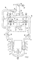
- FIG. 1 shows an air-cooled internal combustion engine 3 arranged in the rear 1 of a motor vehicle (passenger car) 2 with an engine cooling fan 4 and exhaust pipes 5.
- Part of the fresh air drawn in by the engine cooling fan 4 is drawn in by an electric heating fan 6, from which the exhaust pipe 5 is divided into two strands 5 ', 5'.
- the fresh air is heated by exhaust gas heat exchangers 7, 7 'depending on the operating state of the internal combustion engine 3 and conducted in warm air channels 8, 8' to the front.
- the exhaust gas heat exchanger 7, 7 ' encase the exhaust pipes 5', 5 ⁇ in sections.
- each of the two rows of cylinders of the internal combustion engine 3 is assigned a separate exhaust gas heat exchanger 7 or 7 '. Starting from the exhaust gas heat exchangers 7, 7 ', the heated air leading hot air channels 8, 8' are provided, which open into a housing 9 of an air conditioning system 10.
- a flap box 11 with a differential pressure-controlled flap 12 is arranged after the heat exchangers 7, 7', so that the hot air is either guided into the housing 9 of the air conditioning system 10 or blown out into the open (wheel housing 14 ). Furthermore, in the two warm air channels 8, 8 'muffler 15 are arranged.
- the air conditioning system 10 essentially comprises a housing 9 with inflow channels 16, 17, 18 for the warm air, fresh air and circulating air or the cooled air, an evaporator 19, a pressure chamber 20 containing two blowers 34 and outlet channels 21, 22, 23, 23 ′ for the mixed air.
- the inflow duct 16 is assigned to the warm air, while the inflow duct 17 conducts the fresh air and the inflow duct 18 the recirculated air.
- the outlet channel 21 leads into the footwell, the outlet channel 22 to the central nozzle, the outlet channel 23 to the defroster nozzle and the outlet channel 23 'to the side nozzles.
- individually lockable nozzles are provided, through which selectively tempered air can be introduced into the passenger compartment 13.
- the inflow duct 18 for recirculating air opening into the inflow duct 17 for fresh air from the passenger compartment 13 has a pressurized recirculating air flap 24 in the connection area, so that either fresh air or recirculating air or a mixture of fresh air or recirculating air can flow into the cold air duct 25.
- the air recirculation flap 24 is rotatably supported at one end (flutter valve).
- a fresh air flap 26 is provided in the inflow duct 17 for fresh air and is controlled by means of an electric servomotor 27.
- the fresh air flap 26 is mounted in the center and regulated depending on the speed and fan speed. It is closed in recirculation mode, with "max. Cold” and "max. Heating”.
- the evaporator 19 is arranged in the common cold air line 25.
- the cold air line 25 is divided into two sections 28, 29 leading to the side, each section 28, 29 being merged with a hot air duct 8, 8 'and 16 arranged laterally on the outside.
- a temperature mixing flap 31 is provided in each connecting region 30, with which the composition of warm air and cold air can be freely selected.
- Each temperature mixing flap 31 interacts with a servomotor 32.
- a channel 33 leads to the pressure chamber 20, in which the two fans 34 are arranged laterally on the outside.
- the fans 34 are designed as radial fans and are arranged on the suction side with respect to the warm air and the evaporator 19.
- the blowers 34 9 discharge temperature sensors 35 are provided on the housing.
- this air conditioning system 10 warm air and / or fresh air and / or circulating air or cooled air is fed together to at least one blower 34, swirled and mixed therein and after further mixing in the pressure chamber 20 and the individual outlet channels 21, 22, 23, 23 'Fed.
- the two blow-out temperature sensors 35 after the blowers 34 continuously query the temperature deviation ⁇ T from the set target temperature and, if necessary, automatically correct the position of the temperature mixing flaps 31.
- a defined maximum temperature eg 95 ° C.
- the temperature mixing flaps 31 are adjusted so that no warm air can flow more into the fan 34.
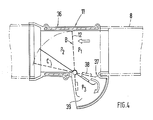
- the arranged in the two warm air channels 8, 8 'arranged differential pressure controlled flaps 12 function depending on the position of the temperature mixing flap 31, i.e. When the warm air duct 8 is closed, the differential pressure-controlled flap 12 opens automatically and the warm air flows out through the exhaust air opening 39.
- the differential pressure-controlled flap 12 comprises a two-part housing 36 made of die-cast aluminum and a flap made of high-alloy sheet metal, which is mounted almost centrally (FIG. 4).
- the flap 12 is provided at the lower end with a spoiler 37 and a balance weight 38.
- the flap 12 In the installed position, the flap 12 is approximately vertical in the housing 36 (position B -max. Cool) and the warm air can flow outside to the outside.
- position B the exhaust air is discharged specifically into the wheel arch 14, so that components such as brake hoses, etc. are not heated.
- a recirculated air / fresh air bypass 40 can also be provided in the air conditioning system 10, so that under certain operating conditions only a small amount of fresh air / circulating air or no fresh air / circulating air flows through the evaporator 19 , but flows around it.
- walls are coated in the pressure chamber 20 with sound-absorbing moldings (not shown in detail).
- the air conditioning system 10 according to the invention is also suitable for vehicles with water-cooled internal combustion engines.
Landscapes
- Physics & Mathematics (AREA)
- Thermal Sciences (AREA)
- Engineering & Computer Science (AREA)
- Mechanical Engineering (AREA)
- Air-Conditioning For Vehicles (AREA)
Applications Claiming Priority (2)
| Application Number | Priority Date | Filing Date | Title |
|---|---|---|---|
| DE3824794A DE3824794A1 (de) | 1988-07-21 | 1988-07-21 | Klimaanlage fuer ein luftgekuehltes kraftfahrzeug |
| DE3824794 | 1988-07-21 |
Publications (3)
| Publication Number | Publication Date |
|---|---|
| EP0351519A2 true EP0351519A2 (fr) | 1990-01-24 |
| EP0351519A3 EP0351519A3 (en) | 1990-05-23 |
| EP0351519B1 EP0351519B1 (fr) | 1992-07-08 |
Family
ID=6359231
Family Applications (1)
| Application Number | Title | Priority Date | Filing Date |
|---|---|---|---|
| EP89109352A Expired - Lifetime EP0351519B1 (fr) | 1988-07-21 | 1989-05-24 | Dispositif de climatisation pour un véhicule automobile refroidi par air |
Country Status (4)
| Country | Link |
|---|---|
| US (1) | US4913347A (fr) |
| EP (1) | EP0351519B1 (fr) |
| DE (2) | DE3824794A1 (fr) |
| ES (1) | ES2033488T3 (fr) |
Cited By (1)
| Publication number | Priority date | Publication date | Assignee | Title |
|---|---|---|---|---|
| EP2080649A3 (fr) * | 2008-01-18 | 2009-11-11 | CLAAS Selbstfahrende Erntemaschinen GmbH | Machine de travail automobile dotée d'une cabine de conducteur |
Families Citing this family (18)
| Publication number | Priority date | Publication date | Assignee | Title |
|---|---|---|---|---|
| EP0372171B1 (fr) * | 1988-10-31 | 1993-10-27 | Dr.Ing.h.c. F. Porsche Aktiengesellschaft | Système de conditionnement d'air |
| DE3843898A1 (de) * | 1988-12-24 | 1990-06-28 | Porsche Ag | Klimatisierungssystem fuer ein fahrzeug |
| US5267451A (en) * | 1992-07-22 | 1993-12-07 | Valeo Climate Control Corporation | Evaporating assembly |
| US5370390A (en) * | 1993-10-26 | 1994-12-06 | Swanson; Wayne L. | Illuminated croquet set |
| US6003593A (en) | 1995-10-31 | 1999-12-21 | Denso International America, Inc. | Automotive vehicle climate control system |
| US5749236A (en) * | 1997-01-27 | 1998-05-12 | Chrysler Corporation | Automatic air recirculation system |
| DE19920823C2 (de) * | 1999-05-06 | 2001-05-31 | Daimler Chrysler Ag | Regelung einer Heiz- und/oder Klimaanlage |
| FR2798323B1 (fr) | 1999-09-10 | 2002-01-18 | Valeo Climatisation | Dispositif de chauffage et/ou climatisation de vehicule automobile avec pulseur perfectionne |
| DE10157499A1 (de) * | 2001-11-23 | 2003-06-12 | Daimler Chrysler Ag | Heiz- und/oder Klimaanlage mit Be- und Entlüftung |
| DE102004016800A1 (de) * | 2004-04-06 | 2005-10-27 | Dr.Ing.H.C. F. Porsche Ag | Kraftfahrzeug mit einem Fahrwerk sowie Vorderachsträger für ein Kraftfahrzeug |
| EP1836064A4 (fr) | 2004-12-30 | 2010-10-06 | American Off Road Technologies | Vehicule a taille reduite ameliore |
| US7416138B2 (en) * | 2005-03-03 | 2008-08-26 | Valeo Climate Control Corp. | Thermal bypass channel |
| US8053126B2 (en) * | 2006-09-29 | 2011-11-08 | GM Global Technology Operations LLC | Water transfer efficiency improvement in a membrane humidifier by reducing dry air inlet temperature |
| DE102010060468A1 (de) | 2010-11-10 | 2012-05-10 | Dr. Ing. H.C. F. Porsche Aktiengesellschaft | Neue Klimagerätegeneration |
| US9168809B2 (en) * | 2012-04-16 | 2015-10-27 | Mahle International Gmbh | Air conditioning system |
| US9168810B2 (en) * | 2012-10-09 | 2015-10-27 | Delphi Technologies, Inc. | Heating and cooling system for occupants of the rear portion of a vehicle |
| DE102016014028B4 (de) * | 2016-11-24 | 2021-09-09 | Daimler Ag | Verfahren und Fahrzeugklimaanlage zum Belüften eines Fahrzeuginnenraums |
| KR102661622B1 (ko) * | 2018-11-12 | 2024-04-29 | 현대자동차주식회사 | 차량용 공조장치 |
Family Cites Families (13)
| Publication number | Priority date | Publication date | Assignee | Title |
|---|---|---|---|---|
| US2764354A (en) * | 1952-11-28 | 1956-09-25 | Vapor Heating Corp | Automatic hydraulic damper |
| US2833298A (en) * | 1954-11-12 | 1958-05-06 | Bailey Meter Co | Ratio control systems |
| US3428115A (en) * | 1967-01-26 | 1969-02-18 | Ranco Inc | Automotive temperature control |
| GB1246803A (en) * | 1967-10-11 | 1971-09-22 | Smiths Industries Ltd | Improvements in or relating to vehicle air conditioning apparatus |
| GB1278202A (en) * | 1970-01-29 | 1972-06-21 | Rolls Royce | Vehicle air conditioning system |
| US3752223A (en) * | 1972-07-31 | 1973-08-14 | Int Harvester Co | Air conditioning apparatus for automotive vehicles |
| GB1423043A (en) * | 1973-04-13 | 1976-01-28 | Rolls Royce Motors Ltd | Vehicle air conditioning system |
| US4210278A (en) * | 1979-02-06 | 1980-07-01 | The United States Of America As Represented By The Administrator Of The National Aeronautics And Space Administration | Apparatus for supplying conditioned air at a substantially constant temperature and humidity |
| DE2914180C2 (de) * | 1979-04-07 | 1982-09-09 | Süddeutsche Kühlerfabrik Julius Fr. Behr GmbH & Co KG, 7000 Stuttgart | Regelvorrichtung für eine Heizungs- oder Klimaanlage, insbesondere für Kraftfahrzeuge |
| JPS57167819A (en) * | 1981-04-10 | 1982-10-15 | Nippon Denso Co Ltd | Air conditioner for automobile |
| DE3217825A1 (de) * | 1982-05-12 | 1983-11-17 | Süddeutsche Kühlerfabrik Julius Fr. Behr GmbH & Co KG, 7000 Stuttgart | Klimaanlage fuer ein luftgekuehltes kraftfahrzeug |
| DE3316060C1 (de) * | 1983-05-03 | 1984-09-20 | Süddeutsche Kühlerfabrik Julius Fr. Behr GmbH & Co KG, 7000 Stuttgart | Elektrische Schaltungsanordnung zum Regeln der Kuehl- und Heizleistung fuer den Innenraum von Kraftfahrzeugen |
| JPS61205511A (ja) * | 1985-03-08 | 1986-09-11 | Nissan Motor Co Ltd | 自動車用加湿装置 |
-
1988
- 1988-07-21 DE DE3824794A patent/DE3824794A1/de active Granted
-
1989
- 1989-05-24 EP EP89109352A patent/EP0351519B1/fr not_active Expired - Lifetime
- 1989-05-24 ES ES198989109352T patent/ES2033488T3/es not_active Expired - Lifetime
- 1989-05-24 DE DE8989109352T patent/DE58901801D1/de not_active Expired - Lifetime
- 1989-07-14 US US07/379,961 patent/US4913347A/en not_active Expired - Fee Related
Cited By (1)
| Publication number | Priority date | Publication date | Assignee | Title |
|---|---|---|---|---|
| EP2080649A3 (fr) * | 2008-01-18 | 2009-11-11 | CLAAS Selbstfahrende Erntemaschinen GmbH | Machine de travail automobile dotée d'une cabine de conducteur |
Also Published As
| Publication number | Publication date |
|---|---|
| EP0351519A3 (en) | 1990-05-23 |
| ES2033488T3 (es) | 1993-03-16 |
| EP0351519B1 (fr) | 1992-07-08 |
| DE3824794A1 (de) | 1990-02-01 |
| DE58901801D1 (de) | 1992-08-13 |
| DE3824794C2 (fr) | 1992-05-27 |
| US4913347A (en) | 1990-04-03 |
Similar Documents
| Publication | Publication Date | Title |
|---|---|---|
| DE3824794C2 (fr) | ||
| DE69301785T2 (de) | Vorrichtung für die Heizung, Lüftung und/oder Klimatisierung eines Fahrzeuginnenraumes | |
| DE19744290A1 (de) | Klimaanlage für ein Fahrzeug | |
| DE29504860U1 (de) | Nach dem Mischluftprinzip arbeitendes Heiz- bzw. Klimagerät | |
| DE19954308C2 (de) | Klimaanlage für Fahrgastzellen von Fahrzeugen | |
| DE19744276A1 (de) | Klimaanlage für ein Fahrzeug | |
| DE3135909C2 (fr) | ||
| DE69619092T2 (de) | Heiz-/Kühlungsvorrichtung einer Kraftfahrzeug-Klimaanlage | |
| DE3046336A1 (de) | Fahrzeug-klimaanlage | |
| DE19919975C1 (de) | Klimaanlage für eine Fahrgastzelle eines Fahrzeugs | |
| EP1228907B1 (fr) | Appareil de climatisation pour véhicule automobile | |
| DE69612910T2 (de) | Vorrichtung zur Heizung und /oder Klimatisierung eines Fahrzeuginnenraumes | |
| DE3514359A1 (de) | Vorrichtung zum beheizen und/oder klimatisieren des innenraums eines fahrzeuges | |
| DE4000990A1 (de) | Heiz- und/oder klimaanlage fuer ein kraftfahrzeug | |
| EP0410283B1 (fr) | Installation de chauffage et/ou de conditionnement d'air pour véhicules automobiles | |
| DE102020007164A1 (de) | Klimaanlage für einen Wärmepumpenbetrieb | |
| DE19741862A1 (de) | Klimaanlage für Fahrzeuge | |
| DE10147113A1 (de) | Vorrichtung zum Temperieren und Belüften von Kraftfahrzeugen | |
| DE19539850C2 (de) | Klima- oder Heizungsanlage für Fahrzeuge | |
| DE60309525T2 (de) | Dachklimaanlage | |
| DE102007049340A1 (de) | Kraftfahrzeug-Klimaanlagenanordnung | |
| EP1284343A2 (fr) | Système de refroidissement pour un véhicule automobile et véhicule automobile correspondant | |
| DE3217825A1 (de) | Klimaanlage fuer ein luftgekuehltes kraftfahrzeug | |
| DE3940362A1 (de) | Heizungs- und/oder klimaanlage | |
| DE19650909C1 (de) | Heizungs- oder Klimaanlage |
Legal Events
| Date | Code | Title | Description |
|---|---|---|---|
| PUAI | Public reference made under article 153(3) epc to a published international application that has entered the european phase |
Free format text: ORIGINAL CODE: 0009012 |
|
| AK | Designated contracting states |
Kind code of ref document: A2 Designated state(s): DE ES FR GB IT |
|
| PUAL | Search report despatched |
Free format text: ORIGINAL CODE: 0009013 |
|
| AK | Designated contracting states |
Kind code of ref document: A3 Designated state(s): DE ES FR GB IT |
|
| 17P | Request for examination filed |
Effective date: 19900921 |
|
| 17Q | First examination report despatched |
Effective date: 19911107 |
|
| ITF | It: translation for a ep patent filed | ||
| GRAA | (expected) grant |
Free format text: ORIGINAL CODE: 0009210 |
|
| AK | Designated contracting states |
Kind code of ref document: B1 Designated state(s): DE ES FR GB IT |
|
| REF | Corresponds to: |
Ref document number: 58901801 Country of ref document: DE Date of ref document: 19920813 |
|
| GBT | Gb: translation of ep patent filed (gb section 77(6)(a)/1977) | ||
| ET | Fr: translation filed | ||
| REG | Reference to a national code |
Ref country code: ES Ref legal event code: FG2A Ref document number: 2033488 Country of ref document: ES Kind code of ref document: T3 |
|
| PGFP | Annual fee paid to national office [announced via postgrant information from national office to epo] |
Ref country code: ES Payment date: 19930511 Year of fee payment: 5 |
|
| PLBE | No opposition filed within time limit |
Free format text: ORIGINAL CODE: 0009261 |
|
| STAA | Information on the status of an ep patent application or granted ep patent |
Free format text: STATUS: NO OPPOSITION FILED WITHIN TIME LIMIT |
|
| 26N | No opposition filed | ||
| PGFP | Annual fee paid to national office [announced via postgrant information from national office to epo] |
Ref country code: GB Payment date: 19940516 Year of fee payment: 6 |
|
| PG25 | Lapsed in a contracting state [announced via postgrant information from national office to epo] |
Ref country code: ES Free format text: LAPSE BECAUSE OF NON-PAYMENT OF DUE FEES Effective date: 19940525 |
|
| PGFP | Annual fee paid to national office [announced via postgrant information from national office to epo] |
Ref country code: FR Payment date: 19940527 Year of fee payment: 6 |
|
| PG25 | Lapsed in a contracting state [announced via postgrant information from national office to epo] |
Ref country code: GB Effective date: 19950524 |
|
| GBPC | Gb: european patent ceased through non-payment of renewal fee |
Effective date: 19950524 |
|
| PG25 | Lapsed in a contracting state [announced via postgrant information from national office to epo] |
Ref country code: FR Effective date: 19960229 |
|
| REG | Reference to a national code |
Ref country code: FR Ref legal event code: ST |
|
| REG | Reference to a national code |
Ref country code: FR Ref legal event code: ST |
|
| PGFP | Annual fee paid to national office [announced via postgrant information from national office to epo] |
Ref country code: DE Payment date: 19960528 Year of fee payment: 8 |
|
| PG25 | Lapsed in a contracting state [announced via postgrant information from national office to epo] |
Ref country code: DE Free format text: LAPSE BECAUSE OF NON-PAYMENT OF DUE FEES Effective date: 19980203 |
|
| REG | Reference to a national code |
Ref country code: ES Ref legal event code: FD2A Effective date: 19990301 |
|
| PG25 | Lapsed in a contracting state [announced via postgrant information from national office to epo] |
Ref country code: IT Free format text: LAPSE BECAUSE OF NON-PAYMENT OF DUE FEES;WARNING: LAPSES OF ITALIAN PATENTS WITH EFFECTIVE DATE BEFORE 2007 MAY HAVE OCCURRED AT ANY TIME BEFORE 2007. THE CORRECT EFFECTIVE DATE MAY BE DIFFERENT FROM THE ONE RECORDED. Effective date: 20050524 |