EP0351571A2 - Vorrichtung zum Heben von Tray-Packungen - Google Patents
Vorrichtung zum Heben von Tray-Packungen Download PDFInfo
- Publication number
- EP0351571A2 EP0351571A2 EP89111269A EP89111269A EP0351571A2 EP 0351571 A2 EP0351571 A2 EP 0351571A2 EP 89111269 A EP89111269 A EP 89111269A EP 89111269 A EP89111269 A EP 89111269A EP 0351571 A2 EP0351571 A2 EP 0351571A2
- Authority
- EP
- European Patent Office
- Prior art keywords
- suction box
- side walls
- tray
- lifting
- support plate
- Prior art date
- Legal status (The legal status is an assumption and is not a legal conclusion. Google has not performed a legal analysis and makes no representation as to the accuracy of the status listed.)
- Granted
Links
- 238000007789 sealing Methods 0.000 claims description 13
- 239000013013 elastic material Substances 0.000 claims description 2
- 238000004873 anchoring Methods 0.000 abstract 1
- 238000004806 packaging method and process Methods 0.000 abstract 1
- 235000015895 biscuits Nutrition 0.000 description 3
- 238000010276 construction Methods 0.000 description 1
- 239000006260 foam Substances 0.000 description 1
- 239000011888 foil Substances 0.000 description 1
- 238000000034 method Methods 0.000 description 1
- 210000000056 organ Anatomy 0.000 description 1
Images




Classifications
-
- B—PERFORMING OPERATIONS; TRANSPORTING
- B65—CONVEYING; PACKING; STORING; HANDLING THIN OR FILAMENTARY MATERIAL
- B65G—TRANSPORT OR STORAGE DEVICES, e.g. CONVEYORS FOR LOADING OR TIPPING, SHOP CONVEYOR SYSTEMS OR PNEUMATIC TUBE CONVEYORS
- B65G47/00—Article or material-handling devices associated with conveyors; Methods employing such devices
- B65G47/74—Feeding, transfer, or discharging devices of particular kinds or types
- B65G47/90—Devices for picking-up and depositing articles or materials
- B65G47/91—Devices for picking-up and depositing articles or materials incorporating pneumatic, e.g. suction, grippers
Definitions
- the invention relates to a device for lifting and / or transporting objects, in particular packs with a bottom part (tray) and individual pieces arranged thereon.
- tray packs are particularly addressed here. These consist of a bottom part (tray) with all-round side shelves of low construction height. Objects such as round (cylindrical), cuboid or otherwise designed individual packs lie or stand on the base part. The aforementioned objects (individual packs) are not fixed on the base part, but may be surrounded by a covering (foil).
- the object of the invention is to reliably and reliably detect such objects or packs for lifting and transporting without impairing the pack itself or its contents.
- the device according to the invention is characterized by a suction box arranged on a lifting member or conveyor, which can be raised and lowered and is at least open at the bottom, which can be placed over the object (pack) and detected by suction air in the suction box.
- a suction box arranged on a lifting member or conveyor, which can be raised and lowered and is at least open at the bottom, which can be placed over the object (pack) and detected by suction air in the suction box.
- the suction air is transferred to a load-bearing part of the object, in particular to the base part, and thus the load-bearing capacity required to lift the object.
- the dimensions of the suction box do not have to be exactly adapted to the object to be lifted. Leakage air can be accepted because the air throughput is sufficient due to an appropriately dimensioned suction unit.
- the sucking air flow is preferably generated by a fan which achieves a sufficiently large air throughput with little energy expenditure,
- the suction box is provided with movable or deformable seals which can be pressed or sucked onto surfaces of the object in the lifting position of the suction box, in particular on side surfaces or on the side rims of the tray.
- movable or deformable seals which can be pressed or sucked onto surfaces of the object in the lifting position of the suction box, in particular on side surfaces or on the side rims of the tray.
- the suction box is provided with foldable side walls which can be pivoted into a spreading position and then into a substantially vertical position in order to place the suction box on the object.
- the foldable side walls are attached to an upper support plate on which the lifting element, in particular an arm of a robot, is also arranged.
- a suction nozzle also connects to the support plate.
- organs for actuating the foldable side walls are attached to their top.
- the handling of particularly critical objects namely cuboidal tray packs 10.
- These usually consist of a tray or a base part 11. This consists of a bottom wall 12 and a circumferential side shelf 13.
- Objects, in the present case biscuit rolls 14, stand on the bottom wall 12 and are laterally embraced by the side board 13.
- the majority of the packaged objects, ie the biscuit rolls 14, protrude beyond the base part 11.
- the tray pack formed in this way can be covered with a film, but is usually open, as in the exemplary embodiment shown.
- the tray pack 10 is to be transported as a unit, in particular lifted and set down, e.g. on a pallet. This loading or transport process should take place automatically, i.e. without manual intervention.
- a lifting element which can be acted upon by suction air is provided, namely a suction box 15 for grasping and holding the tray pack 10 during a lifting or transport movement.
- the suction box 15 is arranged on a conveyor for this purpose.
- the suction box 15 is connected to an arm 17 of a lifting conveyor, in particular a robot, via an upright support rod 16.
- An example of a suitable loading robot is shown and described in DE-A-36 38 991.
- the suction box 15 is placed over the tray pack 10 from above for grasping it. A vacuum is then generated within the suction box 15, as a result of which the tray pack 10 is held in or on the suction box 15.
- the suction air or the negative pressure acts on the base part 11, in particular on the base wall 12, and carries this together with its contents.
- the suction box 15, which is open at the bottom, in the present case consists of an upper support plate 18.
- the support rod 16 is attached to this, namely on the upper side thereof.
- the support plate 18 is provided with a suction connection, namely a suction pipe 19, which is connected via an opening 20 to the interior of the suction box 15.
- the suction pipe 19 is connected to a vacuum source, not shown here, in particular to a fan, which is able to extract large amounts of air at a relatively low vacuum.
- the suction box 15 is also provided with side seals which, in the working or lifting position of the suction box 15, bear against the bottom part 11 in a sealing manner, namely on the side wall 13 thereof.
- elastic sealing strips 21 are on the lower edge of side walls 22 of the suction box 15 attached.
- the side walls 22 end at a distance above the base part 11, while the elastically deformable sealing strips 21 extend to the side rim 13 of the base part 11. Due to negative pressure within the suction box 15, the sealing strips 21 seal against the side board 13 and at the same time transmit load-bearing capacity to the base part 11 as a result of frictional engagement.
- the number and design of the side walls 22 is adapted to the shape of the suction box 15.
- four side walls 22 are arranged opposite one another in pairs.
- the side walls 22 extend up to the upright corner edges of the suction box 15. Upright seals are arranged in the region of these corner edges, namely sealing profiles 23 made of elastic material. These serve to seal corner gaps 24 in the region of adjoining adjacent side walls 22.
- the suction box is brought into a funnel-shaped shape that diverges downwards
- the (four) side walls 22 are attached to the support plate 18 so that they can be moved and folded.
- Each side wall 22 is mounted with a hinge bearing 25 running parallel to the edge on the support plate 18, namely on its upper side adjacent to the edge.
- the side walls 22 can be pivoted about the associated hinge bearing 25, namely from a diverging starting position according to FIG. 2 into the closed or carrying position according to FIG. 1 and FIGS. 3 to 5.
- the side walls 22 are acted upon by actuators for carrying out the pivoting movements.
- a small actuating cylinder 26 is assigned to each side wall 22 as an actuating member and is acted upon, for example, with compressed air.
- a piston rod 27 of the same is moved to pivot the side wall 22 from the inclined position into the upright closed position against a stop of the side wall 22.
- the actuating cylinders 26 assigned to the four side walls 22 are connected to one another via a system of pressure medium lines 28 and to a central compressed air unit (not shown) via a main line 29.
- the side walls 22 are angular in cross section in the present embodiment.
- a leg 30 adjoining the side wall 22 at right angles runs over the almost full length of the side walls 22 on the upper side of the support plate 18. In the corners, the abutting legs 30 are mitred.
- Each leg 30 is pivotally mounted on the top of the support plate 18 with two hinge bearings 25 arranged at a distance from one another.
- the actuating cylinders 26 are located between the hinge bearings 25.
- These or their piston rods 27 act on an upright stop wall 31 of the side walls 22.
- the stop walls 31 are each attached to the legs 30, at right angles to these. In the exemplary embodiment shown, the stop wall 31 extends in the area between the hinge bearings 25 of a side wall 22.
- the piston rods 27 act at a distance from the hinge bearing 25 on the upright or inclined stop walls 31 for pivoting the side walls 22.
- the actuating cylinders 26 bring about an adjustment of the side walls 22 into the upright (closed) position.
- the return to the oblique or diverging starting position (FIG. 2) is ensured by return springs 32 which are fastened to each side wall 22 or to the stop wall 31 of the same on the one hand and to the support plate 18 on the other hand.
- the return springs 32 are biased towards the diverging position of the side walls 22.
- an elastic pad 33 is attached to the underside of the support plate 18, that is to say the object (tray pack 10).
- This consists, for example, of elastic foam.
- the support 33 is designed in the form of a grid with a plurality of recesses 34. Air can be sucked out through the suction pipe 19 through one of these recesses 34.
- the lifting device described proceeds in such a way that the suction box 15 is lowered onto the object by correspondingly actuating a robot or the like when the side walls 22 (FIG. 2) are spread apart.
- the support plate 18 or the support 33 attached to it is preferably located at a short distance above the tray pack 10, so that it is not touched by the suction box 15 in the lower position.
- the side walls 22 are now pivoted into the upright position where received by the sealing strips 21 plant on the side board 13. By generating negative pressure within the suction box 15, the sealing strips 21 are pressed onto the side board 13.
- the tray pack 10 can now be lifted, transported and placed at the desired location.
- the suction box 15 is vented.
- the side walls 22 are pivoted into the inclined position so that the suction box 15 can be lifted off the tray pack 10 without touching it.
Landscapes
- Engineering & Computer Science (AREA)
- Mechanical Engineering (AREA)
- Container Filling Or Packaging Operations (AREA)
- Manipulator (AREA)
- Specific Conveyance Elements (AREA)
Abstract
Description
- Die Erfindung betrifft eine Vorrichtung zum Heben und/oder Transportieren von Gegenständen, insbesondere von Packungen mit einem Bodenteil (Tray) und auf diesem angeordneten stückigen Einzelteilen.
- Die Erfindung befaßt sich mit Maßnahmen zum gesicherten Heben von fördertechnisch schwierigen Gegenständen. Insbesondere sind hier sogenannte Tray-Packungen angesprochen. Diese bestehen aus einem Bodenteil (Tray) mit ringsherumlaufenden Seitenborden geringer Konstruktionshöhe. Auf dem Bodenteil liegen bzw. stehen Gegenstände, wie runde (zylindrische), quaderförmige oder sonstwie gestaltete Einzelpackungen. Die vorgenannten Gegenstände (Einzelpackungen) sind auf dem Bodenteil nicht fixiert, ggf. aber durch eine Umhüllung (Folie) umgeben.
- Beim Anheben und Transportieren derartiger Packungseinheiten ist die verhältnismäßig geringe Stabilität gegenüber mechanischen Belastungen zu berücksichtigen, aber auch der Umstand, daß die Einzelpackungen auf dem Bodenteil nicht verankert sind. Besonders schwierig ist die Handhabung von Packungseinheiten, bei denen die Einzelpackungen gegenüber mechanischen Beanspruchungen empfindlich sind, z.B. bei Tray-Packungen mit Keksrollen.
- Der Erfindung liegt die Aufgabe zugrunde, derartige Gegenstände bzw. Packungen zum Anheben und Transportieren sicher und zuverlässig zu erfassen, ohne die Packung selbst oder deren Inhalt zu beeinträchtigen.
- Zur Lösung dieser Aufgabe ist die erfindungsgemäße Vorrichtung gekennzeichnet durch einen an einem Huborgan oder Förderer angeordneten, heb- und senkbaren, wenigstens unten offenen Saugkasten, der über den Gegenstand (Packung) setzbar ist und diesen durch Saugluft im Saugkasten erfaßt. Dieser ist auf die Abmessungen, insbesondere auf die Grundrißform und -größe des zu hebenden Gegenstandes abgestimmt. Die Saugluft wird auf ein tragendes Teil des Gegenstands, insbesondere auf das Bodenteil übertragen und damit die erforderliche Tragkraft zum Anheben des Gegenstands. Der Saugkasten muß in den Abmessungen nicht exakt an den zu hebenden Gegenstand angepaßt sein. Leckluft kann in Kauf genommen werden, da der Luftdurchsatz aufgrund eines entsprechend bemessenen Saugaggregats ausreichend ist. Der saugende Luftstrom wird vorzugsweise durch einen Ventilator erzeugt, der mit geringem Energieaufwand einen ausreichend großen Luftdurchsatz erreicht,
- Gemäß einem weiteren Vorschlag der Erfindung ist der Saugkasten mit bewegbaren bzw. verformbaren Dichtungen versehen, die in Hubstellung des Saugkastens an Flächen des Gegenstands andrückbar bzw. ansaugbar sind, insbesondere an Seitenflächen bzw. an die Seitenborde des Trays. Durch die saugende Anlage der Dichtungsorgane an dem Gegenstand wird eine zusätzliche Halte- bzw. Tragkraft infolge des Reibschlusses erzeugt.
- Der Saugkasten ist erfindungsgemäß mit klappbaren Seitenwänden versehen, die zum Aufsetzen des Saugkastens auf den Gegenstand in eine Spreizstellung und danach in eine im wesentlichen vertikale Stellung schwenkbar sind. Die klappbaren Seitenwände sind an einer oberen Tragplatte angebracht, an der auch das Huborgan, insbesondere ein Arm eines Roboters, angeordnet ist. Auch ein Saugstutzen schließt an die Tragplatte an. An deren Oberseite sind darüber hinaus Organe zum Betätigen der klappbaren Seitenwände angebracht.
- Weitere Merkmale der Erfindung betreffen die Ausbildung des Saugkastens, insbesondere hinsichtlich der Abdichtung.
- Ein Ausführungsbeispiel der Erfindung wird nachfolgend anhand der Zeichnungen näher erläutert. Es zeigt:
- Fig. 1 eine Vorrichtung zum Heben einer Tray-Packung im Querschnitt als Teil einer Roboters,
- Fig. 2 ein Hubaggregat (Saugkasten) der Vorrichtung gemäß Fig. 1 als Einzelheit bei gespreizten Seitenwänden,
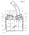
- Fig. 3 eine Darstellung entsprechend Fig. 2 in einer um 90° versetzten, quergerichteten Schnittebene, bei vertikal gerichteten Seitenwänden,
- Fig. 4 den Saugkasten der Vorrichtung in Unteransicht, und
- Fig. 5 den Saugkasten in Draufsicht.
- Bei dem gezeigten Ausführungsbeispiel geht es um die Handhabung besonders kritischer Gegenstände, nämlich quaderförmiger Tray-Packungen 10. Diese bestehen üblicherweise aus einem Tray bzw. einem Bodenteil 11. Dieses besteht aus einer Bodenwand 12 und einem ringsherumlaufenden Seitenbord 13. Gegenstände, im vorliegenden Falle Keksrollen 14, stehen auf der Bodenwand 12 und werden durch das Seitenbord 13 seitlich umfaßt. Die verpackten Gegenstände, also die Keksrollen 14, ragen mit dem überwiegenden Teil über das Bodenteil 11 hinweg. Die so ausgebildete Tray-Packung kann mit einer Folie umhüllt sein, ist jedoch üblicherweise offen, wie bei dem gezeigten Ausführungsbeispiel.
- Die Tray-Packung 10 soll als Einheit transportiert, insbesondere gehoben und abgesetzt werden, z.B. auf einer Palette. Dieser Lade- bzw. Transportvorgang soll selbsttätig erfolgen, also ohne manuelle Eingriffe.
- Zu diesem Zweck ist ein mit Saugluft beaufschlagbares Huborgan vorgesehen, nämlich ein Saugkaseten 15 zum Erfassen und Halten der Tray-Packung 10 während einer Hub- bzw. Transportbewegung. Der Saugkasten 15 ist zu diesem Zweck an einem Förderorgan angeordnet. Bei dem dargestellten Ausführungsbeispiel ist der Saugkasten 15 über eine aufrechte Tragstange 16 mit einem Ausleger bzw. Arm 17 eines Hubförderers, insbesondere eines Roboters, verbunden. Ein Beispiel für einen geeigneten Lade-Roboter ist in der DE-A-36 38 991 dargestellt und beschrieben.
- Der Saugkasten 15 wird zum Erfassen der Tray-Packung 10 von oben her über diese gestülpt. Sodann wird innerhalb des Saugkastens 15 Unterdruck erzeugt, wodurch die Tray-Packung 10 im bzw. am Saugkasten 15 gehalten wird. Die Saugluft bzw. der Unterdruck wirkt dabei auf das Bodenteil 11, insbesondere auf die Bodenwand 12, und trägt diese samt Inhalt.
- Der unten offene Saugkasten 15 besteht im vorliegenden Falle aus einer oberen Tragplatte 18. An dieser, nämlich an deren Oberseite, ist die Tragstange 16 angebracht. Des weiteren ist die Tragplatte 18 mit einem Sauganschluß versehen, nämlich einem Saugrohr 19, das über eine Öffnung 20 mit dem Inneren des Saugkastens 15 verbunden ist. Das Saugrohr 19 ist mit einer hier nicht gezeigten Unterdruckquelle verbunden, insbesondere mit einem Ventilator, der bei verhältnismäßig geringem Unterdruck große Luftmengen abzusaugen vermag.
- Der Saugkasten 15 ist weiterhin mit seitlichen Dichtungen versehen, die in der Arbeits- bzw. Hubstellung des Saugkastens 15 infolge des Unterdrucks dichtend am Bodenteil 11 anliegen, nämlich an dessen Seitenbord 13. Bei dem vorliegenden Ausführungsbeispiel sind elastische Dichtungsstreifen 21 am unteren Rand von Seitenwänden 22 des Saugkastens 15 angebracht. Die Seitenwände 22 enden mit Abstand oberhalb des Bodenteils 11, während sich die elastisch verformbaren Dichtungsstreifen 21 bis zum Seitenbord 13 des Bodenteils 11 erstrecken. Durch Unterdruck innerhalb des Saugkastens 15 legen sich die Dichtungsstreifen 21 dichtend an das Seitenbord 13 an und übertragen damit zugleich Tragkraft auf das Bodenteil 11 infolge von Reibschluß.
- Die Anzahl und Ausgestaltung der Seitenwände 22 ist an die Grundrißform des Saugkastens 15 angepaßt. Bei dem hier gezeigten rechteckigen Saugkasten 15 sind vier Seitenwände 22 einander paarweise gegenüberliegend angeordnet. Die Seitenwände 22 erstrecken sich bis zu aufrechten Eckkanten des Saugkastens 15. Im Bereich dieser Eckkanten sind aufrechte Dichtungen angeordnet, nämlich Dichtungsprofile 23 aus elastischem Werkstoff. Diese dienen zur Abdichtung von Eckspalten 24 im Bereich von aneinanderstoßenden benachbarten Seitenwänden 22.
- Zum Aufsetzen auf einen Gegenstand (Tray-Packung 10) wird der Saugkasten in eine nach unten divergierende, trichterförmige Gestalt gebracht. Zu diesem Zweck sind die (vier) Seitenwände 22 bewegbar, nänlich klappbar an der Tragplatte 18 angebracht. Jede Seitenwand 22 ist mit einem kantenparallel verlaufenden Scharnierlager 25 an der Tragplatte 18, nämlich auf deren Oberseite benachbart zum Rand gelagert. Die Seitenwände 22 sind um das zugeordnete Scharnierlager 25 schwenkbar, nämlich aus einer divergierenden Ausgangsstellung gemäß Fig. 2 in die Schließ- bzw. Tragstellung gemäß Fig. 1 sowie Fig. 3 bis 5.
- Die Seitenwände 22 werden zur Durchführung der Schwenkbewegungen mit Betätigungsorganen beaufschlagt. Bei dem gezeigten Ausführungsbeispiel ist jeder Seitenwand 22 als Betätigungsorgan ein kleiner Betätigungszylinder 26 zugeordnet, der beispielsweise mit Druckluft beaufschlagt wird. Eine Kolbenstange 27 desselben wird zum Verschwenken der Seitenwand 22 aus der Schrägstellung in die aufrechte Schließstellung gegen einen Anschlag der Seitenwand 22 gefahren. Die den vier Seitenwänden 22 zugeordneten Betätigungszylinder 26 sind über ein System von Druckmittelleitungen 28 miteinander und über eine Hauptleitung 29 mit einem zentralen Druckluftaggregat (nicht gezeigt) verbunden.
- Die Seitenwände 22 sind beim vorliegenden Ausführungsbeispiel im Querschnitt winkelförmig ausgebildet. Ein rechtwinklig an die Seitenwand 22 anschließender Schenkel 30 verläuft über die annährend volle Länge der Seitenwände 22 an der Oberseite der Tragplatte 18. In den Ecken sind die aneinanderstoßenden Schenkel 30 auf Gehrung geschnitten.
- Jeder Schenkel 30 ist mit zwei im Abstand voneinander angeordneten Scharnierlagern 25 klappbar an der Oberseite der Tragplatte 18 gelagert. Zwischen den Scharnierlagern 25 befinden sich die Betätigungszylinder 26. diese bzw. deren Kolbenstangen 27 wirken auf eine aufrechte Anschlag wand 31 der Seitenwände 22. Die Anschlagwände 31 sind jeweils an den Schenkeln 30 angebracht, und zwar im rechten Winkel zu diesen. Bei dem gezeigten Ausführungsbeispiel erstreckt sich die Anschlagwand 31 jeweils im Bereich zwischen den Scharnierlagern 25 einer Seitenwand 22. Die Kolbenstangen 27 wirken mit Abstand vom Scharnierlager 25 auf die aufrechten bzw. schräggerichteten Anschlagwände 31 zum Verschwenken der Seitenwände 22.
- Bei dem vorliegenden Ausführungsbeispiel bewirken die Betätigungszylinder 26 eine Verstellung der Seitenwände 22 in die aufrechte (Schließ-)Stellung. Die Rückkehr in die schräggerichtete bzw. divergierende Ausgangsstellung (Fig. 2) wird durch Rückholfedern 32 besorgt, die an jeder Seitenwand 22 bzw. an der Anschlagwand 31 derselben einerseits und an der Tragplatte 18 andererseits befestigt sind. Die Rückholfedern 32 sind in Richtung auf die divergierende Stellung der Seitenwände 22 vorgespannt.
- An der Unterseite der Tragplatte 18, also dem Gegenstand (Tray-Packung 10) zugekehrt, ist bei dem gezeigten Beispiel eine elastische Auflage 33 angebracht. Diese besteht beispielweise aus elastischem Schaumstoff. Die Auflage 33 ist rasterförmig ausgebildet mit einer Vielzahl von Ausnehmungen 34. Durch eine dieser Ausnehmungen 34 kann Luft durch das Saugrohr 19 abgesaugt werden.
- Zum Anheben von Gegenständen, z.B. Tray-Packungen 10, wird mit der beschriebenen Hubvorrichtung so vorgegangen, daß der Saugkasten 15 durch entsprechendes Betätigen eines Roboters oder dgl. bei gespreizten Seitenwänden 22 (Fig. 2) auf den Gegenstand abgesenkt wird. Vorzugsweise befindet sich die Tragplatte 18 bzw. die an dieser angebrachte Auflage 33 mit einem geringen Abstand oberhalb der Tray-Packung 10, so daß diese in der unteren Position des Saugkastens 15 von diesem nicht berührt wird. Die Seitenwände 22 werden nun in die aufrechte Position geschwenkt, wo durch die Dichtungsstreifen 21 Anlage am Seitenbord 13 erhalten. Durch Erzeugen von Unterdruck innerhalb des Saugkastens 15 werden die Dichtungsstreifen 21 an den Seitenbord 13 angedrückt. Durch die Wirkung des Unterdruckes im Saugkasten 15 und zusätzlich durch Reibkräfte zwischen Dichtungsstreifen 21 und Seitenbord 13 kann nunmehr die Tray-Packung 10 angehoben, transportiert und an der gewünschten Stelle abgesetzt werden. Beim Absetzen wird der Saugkasten 15 entlüftet. Die Seitenwände 22 werden in die Schrägstellung verschwenkt, so daß der Saugkasten 15 ohne Berührung der Tray-Packung 10 von dieser wieder abgehoben werden kann.
Claims (10)
Applications Claiming Priority (2)
| Application Number | Priority Date | Filing Date | Title |
|---|---|---|---|
| DE3824155A DE3824155A1 (de) | 1988-07-16 | 1988-07-16 | Vorrichtung zum heben von tray-packungen |
| DE3824155 | 1988-07-16 |
Publications (3)
| Publication Number | Publication Date |
|---|---|
| EP0351571A2 true EP0351571A2 (de) | 1990-01-24 |
| EP0351571A3 EP0351571A3 (en) | 1990-12-19 |
| EP0351571B1 EP0351571B1 (de) | 1994-06-08 |
Family
ID=6358817
Family Applications (1)
| Application Number | Title | Priority Date | Filing Date |
|---|---|---|---|
| EP89111269A Expired - Lifetime EP0351571B1 (de) | 1988-07-16 | 1989-06-21 | Vorrichtung zum Heben von Tray-Packungen |
Country Status (6)
| Country | Link |
|---|---|
| US (1) | US5088878A (de) |
| EP (1) | EP0351571B1 (de) |
| JP (1) | JPH0262316A (de) |
| BR (1) | BR8903434A (de) |
| CA (1) | CA1323057C (de) |
| DE (2) | DE3824155A1 (de) |
Cited By (10)
| Publication number | Priority date | Publication date | Assignee | Title |
|---|---|---|---|---|
| EP0415210A1 (de) * | 1989-08-31 | 1991-03-06 | Owens-Brockway Glass Container Inc. | Aufnahmearm zum Laden eines Ofens |
| EP0578346A1 (de) * | 1992-07-08 | 1994-01-12 | MANNESMANN Aktiengesellschaft | Greifvorrichtung |
| WO1995030615A1 (en) * | 1994-05-09 | 1995-11-16 | Autocast Inventions Limited | A grid element and an apparatus incorporating the grid element for assisting in the stacking and destacking of products from a surface |
| WO1996002444A1 (de) * | 1994-07-15 | 1996-02-01 | Aft Automatisierungs- Und Fördertechnik Gmbh | Lageranlage zum kommissionieren |
| EP0736468A1 (de) * | 1995-04-06 | 1996-10-09 | Josef Meindl Beteiligungs oHG | Vorrichtung zum Umsetzen von verformbaren, plattenförmigen Gegenständen, insbesondere Ziegelformlingen |
| US5813713A (en) * | 1991-11-27 | 1998-09-29 | Autocast Inventions Limited | Grid element and an apparatus incorporating the grid element for assisting in the stacking and destacking of products from a surface |
| US6802688B1 (en) | 1999-04-27 | 2004-10-12 | Univeyor A/S | Apparatus for handling layers of palletized goods |
| FR2983462A1 (fr) * | 2011-12-06 | 2013-06-07 | Packetis | Manipulation d'un ensemble compact d'une pluralite d'objets comme des produits de cartonnerie tels que des flans ou des boitages plies sur eux-memes. |
| WO2014161549A1 (en) * | 2013-04-02 | 2014-10-09 | Inva Invest Holding Aps | A flow blocking valve, a vacuum lifting device and a method for operating a vacuum lifting device |
| EP4600188A1 (de) * | 2021-07-14 | 2025-08-13 | Newteq Holding B.V. | Automatisierte lagersysteme, anordnungen, vorrichtungen und verfahren zur montage gemischter paletten und zur erleichterung der kommissionierung |
Families Citing this family (46)
| Publication number | Priority date | Publication date | Assignee | Title |
|---|---|---|---|---|
| DE4222355C2 (de) * | 1992-03-24 | 1995-12-07 | Schmalz J Gmbh | Greifvorrichtung |
| US5516255A (en) * | 1994-04-25 | 1996-05-14 | Tygard Machine & Manufacturing Co. | Clamping apparatus |
| DE4425003A1 (de) * | 1994-07-15 | 1996-01-18 | Hes Liselotte | Verfahren und Vorrichtung zum Verpacken und Entpacken von Gebinden |
| DE19618344A1 (de) * | 1996-05-08 | 1997-11-13 | Focke & Co | Vorrichtung zum Handhaben von Zuschnittstapeln |
| CA2209980C (en) * | 1996-07-11 | 2008-01-08 | Tygard Machine And Manufacturing Company | Clamping apparatus |
| US5908283A (en) | 1996-11-26 | 1999-06-01 | United Parcel Service Of Americia, Inc. | Method and apparatus for palletizing packages of random size and weight |
| US6543010B1 (en) | 1999-02-24 | 2003-04-01 | Hewlett-Packard Development Company, L.P. | Method and apparatus for accelerating a memory dump |
| DE19959285B4 (de) * | 1999-12-09 | 2008-01-31 | J. Schmalz Gmbh | Vakuum-Greifsystem zum Greifen eines Objekts und Handhabungsgerät zum Handhaben eines Objekts mit Hilfe eines Vakuum-Greifsystems |
| ATE375946T1 (de) * | 2000-06-08 | 2007-11-15 | Bosch Gmbh Robert | Greifvorrichtung zum erfassen von gegenständen und verfahren zum betreiben derselben |
| US6860531B2 (en) * | 2001-12-20 | 2005-03-01 | Abb Inc. | Gripping and vacuum end effector for transferring articles |
| US7134833B2 (en) * | 2004-08-03 | 2006-11-14 | Flexicell, Inc. | Servo adjustable gripper device |
| US7017961B1 (en) * | 2004-08-06 | 2006-03-28 | Bakery Holdings Llc | Compressive end effector |
| JP2008512321A (ja) * | 2004-09-13 | 2008-04-24 | ミードウエストベコ・コーポレーション | 封筒束および封筒束のパッケージの組立方法 |
| US7789226B2 (en) * | 2004-09-13 | 2010-09-07 | Meadwestvaco Corporation | Packaged banded envelopes |
| US20060056951A1 (en) * | 2004-09-15 | 2006-03-16 | Jeffrey Todd Williamson | Material handling system |
| US7637711B2 (en) * | 2005-02-08 | 2009-12-29 | Meadwestvaco Corporation | Apparatus with suction head for moving envelopes |
| US7481472B2 (en) * | 2005-03-15 | 2009-01-27 | Sage Automation, Inc. | Layer picking end effector system, apparatus and method |
| AT503572B1 (de) * | 2006-08-03 | 2007-11-15 | Tgw Transportgeraete Gmbh | Fördereinrichtung zum depalettieren von auf einem warenträger gestapelter waren |
| US9592970B2 (en) * | 2008-07-17 | 2017-03-14 | Toby D. Henderson | Robotic gantry with end effector for product lifting |
| US9469490B2 (en) * | 2008-08-06 | 2016-10-18 | Dyco, Inc. | Apparatus and method of palletizing loose-piece articles |
| US7950708B2 (en) | 2008-08-15 | 2011-05-31 | Amf Automation Technologies, Inc. | Programmable zoned end effector |
| US8684434B2 (en) | 2011-11-02 | 2014-04-01 | AMF automation Technologies, LLC | End effector with internal valve |
| US8864200B2 (en) | 2010-04-20 | 2014-10-21 | AMF automation Technologies, LLC | End effector with internal valve |
| US8251415B2 (en) | 2010-04-20 | 2012-08-28 | AMF automation Technologies, LLC | End effector with suction cups having internal valves |
| US20110293397A1 (en) | 2010-05-25 | 2011-12-01 | Lomerson Jr Roland | End Effector for Picking, Forming, and Inserting U-Shaped Packing Insert |
| US8528955B2 (en) | 2011-01-24 | 2013-09-10 | AMF automation Technologies, LLC | Robot end effector with cable management |
| US20130015675A1 (en) * | 2011-07-15 | 2013-01-17 | Douglas Pickard | Apparatus, system, and method for layer picking and order fulfillment for items stored in a warehouse |
| JP5866097B2 (ja) * | 2012-03-07 | 2016-02-17 | 西部電機株式会社 | 吸着具およびピッキング装置 |
| US9061868B1 (en) * | 2012-07-19 | 2015-06-23 | Wepco., Inc. | Vacuum-assisted carton or box lifter |
| FR2997031B1 (fr) * | 2012-10-23 | 2016-07-01 | Bel Fromageries | Dispositif de prehension d'au moins un produit deformable. |
| US9211679B1 (en) | 2013-05-03 | 2015-12-15 | The Boeing Company | Systems and methods of forming a skin for a composite structure and composite structures including the same |
| TW201507956A (zh) * | 2013-08-27 | 2015-03-01 | Hon Hai Prec Ind Co Ltd | 吸取裝置 |
| US11059185B2 (en) * | 2014-10-03 | 2021-07-13 | Frito-Lay North America, Inc. | Apparatus and method for transferring a pattern from a universal surface to an ultimate package |
| CN106794967B (zh) * | 2014-10-13 | 2019-05-28 | J.施迈茨有限公司 | 电池夹具 |
| US9663247B2 (en) * | 2015-02-27 | 2017-05-30 | The Boeing Company | Systems, methods, and vacuum chucks for transferring flexible elongate bodies |
| CA2998128C (en) | 2015-09-08 | 2023-11-28 | Berkshire Grey, Inc. | Systems and methods for providing high flow vacuum acquisition in automated systems |
| US10005234B2 (en) | 2015-10-29 | 2018-06-26 | The Boeing Company | Devices, systems, and methods for compacting a charge of composite material across an edge |
| WO2017094109A1 (ja) * | 2015-12-01 | 2017-06-08 | 富士機械製造株式会社 | ワーク移載装置及びワーク移載システム |
| IT201700101371A1 (it) * | 2017-09-11 | 2019-03-11 | Ocme Srl | Organo di presa di uno strato di prodotti. |
| US10676299B2 (en) * | 2018-04-07 | 2020-06-09 | Roca Robotics, Inc. | Item inventory management system with vacuum operated robotic card sorter |
| DE102018120155B4 (de) * | 2018-08-20 | 2021-04-22 | J. Schmalz Gmbh | Sauggreifer mit variabler Saugfläche |
| JP7263809B2 (ja) * | 2019-02-07 | 2023-04-25 | 富士電機株式会社 | 保持機構及び搬送装置 |
| JP2020189341A (ja) * | 2019-05-17 | 2020-11-26 | 株式会社イシダ | 吸着搬送装置 |
| US11623352B2 (en) * | 2020-06-24 | 2023-04-11 | JLS Automation | Automated bag gripping device |
| EP4247599B1 (de) * | 2020-11-19 | 2025-08-20 | Berkshire Grey Operating Company, Inc. | Systeme und verfahren zur objektverarbeitung unter verwendung von greifern für objekte mit niedriger haltungsautorität |
| US11826904B2 (en) * | 2020-11-25 | 2023-11-28 | The Boeing Company | End effector, system and method for picking up and placing an object |
Family Cites Families (12)
| Publication number | Priority date | Publication date | Assignee | Title |
|---|---|---|---|---|
| US3387718A (en) * | 1966-03-10 | 1968-06-11 | Alvey Conveyor Mfg Company | Pallet loading and unloading apparatus |
| US3404787A (en) * | 1966-12-27 | 1968-10-08 | American Chain & Cable Co | Suction lift for article distribution and storage system |
| DE1756327A1 (de) * | 1968-05-08 | 1970-04-02 | Alvey Conveyor Mfg Company | Vorrichtung zum Be- und Entladen von Paletten |
| US3556579A (en) * | 1968-06-17 | 1971-01-19 | Nat Res Dev | Suction pads |
| FR2166242B1 (de) * | 1972-01-03 | 1976-01-16 | Applic Procedes Electriq Fr | |
| US4355936A (en) * | 1980-08-28 | 1982-10-26 | Diamond International Corporation | Egg transfer apparatus |
| FR2519619B1 (fr) * | 1982-01-11 | 1986-02-21 | Carnaud Emballage Sa | Procede et dispositif de prehension par aspiration |
| NO161311C (no) * | 1983-02-24 | 1989-08-02 | Reinhard Goepfert | Selvdrevet innretning for hevning og forflytning av elementer som skal loeftes. |
| IT1176164B (it) * | 1984-05-22 | 1987-08-18 | Bini & C Srl | Procedimento ed apparecchiatura per il sollevamento ed il trasporto di oggetti sistemati su supporti a vassoio o simili |
| DE3419913C2 (de) * | 1984-05-28 | 1987-01-22 | Max Kettner Verpackungsmaschinenfabrik GmbH & Co KG, 8000 München | Vorrichtung zum Anheben und Transportieren mindestens einer Lage von Gebinden |
| FR2579190B1 (fr) * | 1985-03-21 | 1988-10-14 | Thibault Jacques | Dispositif de levage de charges en couches formees d'objets independants les uns des autres et disposes cote a cote |
| US4753564A (en) * | 1987-01-23 | 1988-06-28 | Goldco Industries, Inc. | Apparatus and method for effecting movement of selected tiers of stacked articles using pressure differentials |
-
1988
- 1988-07-16 DE DE3824155A patent/DE3824155A1/de not_active Withdrawn
-
1989
- 1989-06-21 EP EP89111269A patent/EP0351571B1/de not_active Expired - Lifetime
- 1989-06-21 DE DE58907814T patent/DE58907814D1/de not_active Expired - Fee Related
- 1989-06-28 CA CA000604226A patent/CA1323057C/en not_active Expired - Fee Related
- 1989-07-07 JP JP1174314A patent/JPH0262316A/ja active Pending
- 1989-07-13 BR BR898903434A patent/BR8903434A/pt not_active IP Right Cessation
-
1991
- 1991-01-09 US US07/637,967 patent/US5088878A/en not_active Expired - Lifetime
Cited By (11)
| Publication number | Priority date | Publication date | Assignee | Title |
|---|---|---|---|---|
| EP0415210A1 (de) * | 1989-08-31 | 1991-03-06 | Owens-Brockway Glass Container Inc. | Aufnahmearm zum Laden eines Ofens |
| US5813713A (en) * | 1991-11-27 | 1998-09-29 | Autocast Inventions Limited | Grid element and an apparatus incorporating the grid element for assisting in the stacking and destacking of products from a surface |
| EP0578346A1 (de) * | 1992-07-08 | 1994-01-12 | MANNESMANN Aktiengesellschaft | Greifvorrichtung |
| WO1995030615A1 (en) * | 1994-05-09 | 1995-11-16 | Autocast Inventions Limited | A grid element and an apparatus incorporating the grid element for assisting in the stacking and destacking of products from a surface |
| WO1996002444A1 (de) * | 1994-07-15 | 1996-02-01 | Aft Automatisierungs- Und Fördertechnik Gmbh | Lageranlage zum kommissionieren |
| EP0736468A1 (de) * | 1995-04-06 | 1996-10-09 | Josef Meindl Beteiligungs oHG | Vorrichtung zum Umsetzen von verformbaren, plattenförmigen Gegenständen, insbesondere Ziegelformlingen |
| US6802688B1 (en) | 1999-04-27 | 2004-10-12 | Univeyor A/S | Apparatus for handling layers of palletized goods |
| FR2983462A1 (fr) * | 2011-12-06 | 2013-06-07 | Packetis | Manipulation d'un ensemble compact d'une pluralite d'objets comme des produits de cartonnerie tels que des flans ou des boitages plies sur eux-memes. |
| WO2014161549A1 (en) * | 2013-04-02 | 2014-10-09 | Inva Invest Holding Aps | A flow blocking valve, a vacuum lifting device and a method for operating a vacuum lifting device |
| US9731423B2 (en) | 2013-04-02 | 2017-08-15 | Inva Invest Holding Aps | Flow blocking valve, a vacuum lifting device and a method for operating a vacuum lifting device |
| EP4600188A1 (de) * | 2021-07-14 | 2025-08-13 | Newteq Holding B.V. | Automatisierte lagersysteme, anordnungen, vorrichtungen und verfahren zur montage gemischter paletten und zur erleichterung der kommissionierung |
Also Published As
| Publication number | Publication date |
|---|---|
| US5088878A (en) | 1992-02-18 |
| DE58907814D1 (de) | 1994-07-14 |
| EP0351571A3 (en) | 1990-12-19 |
| JPH0262316A (ja) | 1990-03-02 |
| CA1323057C (en) | 1993-10-12 |
| EP0351571B1 (de) | 1994-06-08 |
| DE3824155A1 (de) | 1990-01-25 |
| BR8903434A (pt) | 1990-03-06 |
Similar Documents
| Publication | Publication Date | Title |
|---|---|---|
| EP0351571B1 (de) | Vorrichtung zum Heben von Tray-Packungen | |
| EP3730432B1 (de) | Vorrichtung und verfahren zum depalettieren von stapelbaren stückgutgebinden | |
| DE102011015138B4 (de) | Hängeförder-Transporttasche und Verfahren zum automatisierten Entladen der Transporttasche | |
| EP0077508B1 (de) | Verfahren und Vorrichtung zum Verpacken von palettierten Gutstapeln | |
| DE4030215C2 (de) | Vorrichtung zum Handhaben von Becherstangen sowie Verwendung eines speziellen Behälters für Becherstangen | |
| EP0482406A1 (de) | Vorrichtung zum Handhaben von Gegenständen, wie Kartons | |
| EP2874925A1 (de) | Verfahren und greiferkopf zur entnahme von stückgutgebinden von einem stapel | |
| DE602005006006T3 (de) | Handhabungseinheit zum palettieren | |
| DE102006062528A1 (de) | Vorrichtung und Verfahren zur Umsetzung von Stückgut | |
| EP0784017A1 (de) | Aufnahmegestell für fliessfähige Massen | |
| DE102019128197B4 (de) | Depalettieranordnung mit einer Vorrichtung zum Depalettieren von stapelbaren Stückgutgebinden und Verfahren zum Depalettieren von stapelbaren Stückgutgebinden | |
| EP0437760A2 (de) | Vorrichtung zum Abheben von (Zwischen-)Lagen gestapelter Gegenstände | |
| DE102004004146B3 (de) | Vorrichtung und Verfahren zum Sichern von gestapelten Gegenständen | |
| EP0578346A1 (de) | Greifvorrichtung | |
| DE4222355C2 (de) | Greifvorrichtung | |
| DE102020006488B3 (de) | Logistiksystem zum Zuführen von Lagerteilen von einem Lagerort zu einer Entnahmestelle | |
| DE102019123805B4 (de) | Anordnung zum Bearbeiten einer Sendung | |
| DE4402610A1 (de) | Vorrichtung zum Handhaben von Gruppen von Gegenständen, insbesondere Verpackungsbehältern | |
| DE7541253U (de) | Vorrichtung zum laden von gegenstaenden auf paletten o.dgl. | |
| DE1506508C (de) | Greif- und Transportvorrichtung mit Saugkopf für Plattenstapel | |
| DE3204171A1 (de) | Vorrichtung zum verpacken von palettierten gutstapeln | |
| DE8203223U1 (de) | Vorrichtung zum Verpacken von palettierten Gutstapeln | |
| DE2743205A1 (de) | Behaelter zur lagerung und zum transport von artikeln | |
| DD256978A3 (de) | Anordnung zur aufnahme und uebergabe von gefuellten saecken | |
| DE4036132A1 (de) | Transportbehaelter zur aufnahme von guetern unter geregeltem unterdruck |
Legal Events
| Date | Code | Title | Description |
|---|---|---|---|
| PUAI | Public reference made under article 153(3) epc to a published international application that has entered the european phase |
Free format text: ORIGINAL CODE: 0009012 |
|
| AK | Designated contracting states |
Kind code of ref document: A2 Designated state(s): DE FR GB IT |
|
| PUAL | Search report despatched |
Free format text: ORIGINAL CODE: 0009013 |
|
| AK | Designated contracting states |
Kind code of ref document: A3 Designated state(s): DE FR GB IT |
|
| 17P | Request for examination filed |
Effective date: 19901220 |
|
| 17Q | First examination report despatched |
Effective date: 19921221 |
|
| GRAA | (expected) grant |
Free format text: ORIGINAL CODE: 0009210 |
|
| AK | Designated contracting states |
Kind code of ref document: B1 Designated state(s): DE FR GB IT |
|
| GBT | Gb: translation of ep patent filed (gb section 77(6)(a)/1977) |
Effective date: 19940610 |
|
| REF | Corresponds to: |
Ref document number: 58907814 Country of ref document: DE Date of ref document: 19940714 |
|
| ITF | It: translation for a ep patent filed | ||
| ET | Fr: translation filed | ||
| PLBE | No opposition filed within time limit |
Free format text: ORIGINAL CODE: 0009261 |
|
| STAA | Information on the status of an ep patent application or granted ep patent |
Free format text: STATUS: NO OPPOSITION FILED WITHIN TIME LIMIT |
|
| 26N | No opposition filed | ||
| REG | Reference to a national code |
Ref country code: GB Ref legal event code: IF02 |
|
| PGFP | Annual fee paid to national office [announced via postgrant information from national office to epo] |
Ref country code: DE Payment date: 20070623 Year of fee payment: 19 |
|
| PGFP | Annual fee paid to national office [announced via postgrant information from national office to epo] |
Ref country code: GB Payment date: 20070620 Year of fee payment: 19 |
|
| PGFP | Annual fee paid to national office [announced via postgrant information from national office to epo] |
Ref country code: IT Payment date: 20070626 Year of fee payment: 19 |
|
| PGFP | Annual fee paid to national office [announced via postgrant information from national office to epo] |
Ref country code: FR Payment date: 20070608 Year of fee payment: 19 |
|
| GBPC | Gb: european patent ceased through non-payment of renewal fee |
Effective date: 20080621 |
|
| REG | Reference to a national code |
Ref country code: FR Ref legal event code: ST Effective date: 20090228 |
|
| PG25 | Lapsed in a contracting state [announced via postgrant information from national office to epo] |
Ref country code: DE Free format text: LAPSE BECAUSE OF NON-PAYMENT OF DUE FEES Effective date: 20090101 |
|
| PG25 | Lapsed in a contracting state [announced via postgrant information from national office to epo] |
Ref country code: GB Free format text: LAPSE BECAUSE OF NON-PAYMENT OF DUE FEES Effective date: 20080621 |
|
| PG25 | Lapsed in a contracting state [announced via postgrant information from national office to epo] |
Ref country code: IT Free format text: LAPSE BECAUSE OF NON-PAYMENT OF DUE FEES Effective date: 20080621 Ref country code: FR Free format text: LAPSE BECAUSE OF NON-PAYMENT OF DUE FEES Effective date: 20080630 |