EP0351673A2 - Palier de butée - Google Patents
Palier de butée Download PDFInfo
- Publication number
- EP0351673A2 EP0351673A2 EP89112482A EP89112482A EP0351673A2 EP 0351673 A2 EP0351673 A2 EP 0351673A2 EP 89112482 A EP89112482 A EP 89112482A EP 89112482 A EP89112482 A EP 89112482A EP 0351673 A2 EP0351673 A2 EP 0351673A2
- Authority
- EP
- European Patent Office
- Prior art keywords
- thrust bearing
- bearing device
- shoe member
- sliding shoe
- sliding
- Prior art date
- Legal status (The legal status is an assumption and is not a legal conclusion. Google has not performed a legal analysis and makes no representation as to the accuracy of the status listed.)
- Withdrawn
Links
- 239000007788 liquid Substances 0.000 claims abstract description 8
- 239000002184 metal Substances 0.000 claims abstract description 4
- 229910000897 Babbitt (metal) Inorganic materials 0.000 claims description 2
- OKTJSMMVPCPJKN-UHFFFAOYSA-N Carbon Chemical compound [C] OKTJSMMVPCPJKN-UHFFFAOYSA-N 0.000 claims description 2
- 229910052799 carbon Inorganic materials 0.000 claims description 2
- 229920003023 plastic Polymers 0.000 claims description 2
- 239000004033 plastic Substances 0.000 claims description 2
- 239000000306 component Substances 0.000 description 12
- 238000004519 manufacturing process Methods 0.000 description 9
- 238000012423 maintenance Methods 0.000 description 5
- 238000000034 method Methods 0.000 description 3
- 238000009434 installation Methods 0.000 description 2
- 238000003754 machining Methods 0.000 description 2
- 230000002411 adverse Effects 0.000 description 1
- 238000005266 casting Methods 0.000 description 1
- 239000004020 conductor Substances 0.000 description 1
- 230000000694 effects Effects 0.000 description 1
- 238000005495 investment casting Methods 0.000 description 1
- 230000001050 lubricating effect Effects 0.000 description 1
- 239000000463 material Substances 0.000 description 1
Images


Classifications
-
- F—MECHANICAL ENGINEERING; LIGHTING; HEATING; WEAPONS; BLASTING
- F16—ENGINEERING ELEMENTS AND UNITS; GENERAL MEASURES FOR PRODUCING AND MAINTAINING EFFECTIVE FUNCTIONING OF MACHINES OR INSTALLATIONS; THERMAL INSULATION IN GENERAL
- F16C—SHAFTS; FLEXIBLE SHAFTS; ELEMENTS OR CRANKSHAFT MECHANISMS; ROTARY BODIES OTHER THAN GEARING ELEMENTS; BEARINGS
- F16C33/00—Parts of bearings; Special methods for making bearings or parts thereof
- F16C33/02—Parts of sliding-contact bearings
- F16C33/04—Brasses; Bushes; Linings
- F16C33/06—Sliding surface mainly made of metal
- F16C33/10—Construction relative to lubrication
- F16C33/1025—Construction relative to lubrication with liquid, e.g. oil, as lubricant
- F16C33/106—Details of distribution or circulation inside the bearings, e.g. details of the bearing surfaces to affect flow or pressure of the liquid
- F16C33/108—Details of distribution or circulation inside the bearings, e.g. details of the bearing surfaces to affect flow or pressure of the liquid with a plurality of elements forming the bearing surfaces, e.g. bearing pads
-
- F—MECHANICAL ENGINEERING; LIGHTING; HEATING; WEAPONS; BLASTING
- F16—ENGINEERING ELEMENTS AND UNITS; GENERAL MEASURES FOR PRODUCING AND MAINTAINING EFFECTIVE FUNCTIONING OF MACHINES OR INSTALLATIONS; THERMAL INSULATION IN GENERAL
- F16C—SHAFTS; FLEXIBLE SHAFTS; ELEMENTS OR CRANKSHAFT MECHANISMS; ROTARY BODIES OTHER THAN GEARING ELEMENTS; BEARINGS
- F16C17/00—Sliding-contact bearings for exclusively rotary movement
- F16C17/04—Sliding-contact bearings for exclusively rotary movement for axial load only
- F16C17/06—Sliding-contact bearings for exclusively rotary movement for axial load only with tiltably-supported segments, e.g. Michell bearings
- F16C17/065—Sliding-contact bearings for exclusively rotary movement for axial load only with tiltably-supported segments, e.g. Michell bearings the segments being integrally formed with, or rigidly fixed to, a support-element
-
- F—MECHANICAL ENGINEERING; LIGHTING; HEATING; WEAPONS; BLASTING
- F16—ENGINEERING ELEMENTS AND UNITS; GENERAL MEASURES FOR PRODUCING AND MAINTAINING EFFECTIVE FUNCTIONING OF MACHINES OR INSTALLATIONS; THERMAL INSULATION IN GENERAL
- F16C—SHAFTS; FLEXIBLE SHAFTS; ELEMENTS OR CRANKSHAFT MECHANISMS; ROTARY BODIES OTHER THAN GEARING ELEMENTS; BEARINGS
- F16C33/00—Parts of bearings; Special methods for making bearings or parts thereof
- F16C33/02—Parts of sliding-contact bearings
- F16C33/04—Brasses; Bushes; Linings
- F16C33/16—Sliding surface consisting mainly of graphite
-
- F—MECHANICAL ENGINEERING; LIGHTING; HEATING; WEAPONS; BLASTING
- F16—ENGINEERING ELEMENTS AND UNITS; GENERAL MEASURES FOR PRODUCING AND MAINTAINING EFFECTIVE FUNCTIONING OF MACHINES OR INSTALLATIONS; THERMAL INSULATION IN GENERAL
- F16C—SHAFTS; FLEXIBLE SHAFTS; ELEMENTS OR CRANKSHAFT MECHANISMS; ROTARY BODIES OTHER THAN GEARING ELEMENTS; BEARINGS
- F16C2380/00—Electrical apparatus
- F16C2380/26—Dynamo-electric machines or combinations therewith, e.g. electro-motors and generators
Definitions
- the present invention relates to a thrust bearing device and more particularly to such a device that is used in an electric motor, for example, a submersible motor, wherein liquid is contained within the casing thereof to lubricate the thrust bearing device.
- a thrust bearing device of the type referred to above has involved the use of plural tilting pads, each pad being designed to have a particular configuration such as projecting or inflating in the central region thereof. These pads serve to constitute one of the opposing sliding surfaces. Use of these pads has in turn involved the employment of several related means and many parts which demand additional expense for the installation and maintenance thereof, maintenance being difficult.
- Fig. 1 illustrates a typical conventional thrust bearing device employing such tilting pads.
- the rotary side of the bearing device comprises a rotary disk 101 and a thrust disk 103 adapted to hold in place the rotary disk 101 and attached to a primary shaft 102
- the stationary side of the device comprises a plurality of tilting pads 104 adapted to slidably contact the sliding surface of the rotary disk 101, components 105 for retaining the tilting pads 104, and a complicated alignment mechanism constituted by several components 106 adapted to keep the respective sliding surfaces of the tilting pads 105 coplanar.
- This stationary side of the bearing device is simply placed on a bracket 107 of the motor.
- Each of the sliding surfaces of the tilting pads 104 is given a particular shape which is configured in a so-called centrally projected or inflated shape, the center portion being higher than the opposite ends, so that a wedge shaped lubricating film is properly formed between the centrally projected surfaces of the tilting pads 104 and the surface of the rotary disk 101 during the relative rotation therebetween.
- the reference numeral 108 denotes a radial bearing, 109 a rotor, and 110 a stator.
- the present invention provides a thrust bearing device for an electric motor lubricated by liquid within a motor casing which comprises a rotary disk directly or indirectly fixed on a primary shaft of the motor and a sliding shoe member having sliding surfaces slidably in contact with a sliding surface of the rotary disk.
- the sliding shoe member is made of metal and is provided with a plurality of segmented shoes unitarily connected to a common base through respective ribs.
- the sliding shoe member is fixed to a motor bracket with a gap having a predetermined configuration provided between the retaining surface of the motor bracket and the bottom surface of the common base of the sliding shoe member at each of the portions thereof which respectively correspond to the shoes.
- the shoes when a load is applied to the thrust bearing device, the shoes are deformed elastically and a liquid film in a wedge shape is formed between the rotary disk and the shoes.
- a high load bearing capacity can be expected of this device, as in the case of a conventional thrust bearing device employing a tilting pad system.
- the gap that is present between the common base of the sliding shoe member and the motor bracket absorbs the deflection caused by the inevitable manufacturing tolerances on the sliding surface of the disk and the top surface of the bracket, thereby preventing local contact of the sliding surfaces of the shoes of the sliding shoe member, and thus enabling the sliding mode of the shoes to be kept uniform.
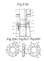
- Figs. 2(a) to 2(e) shows in combination a first embodiment of the thrust bearing device according to the present invention, in which:
- the reference numeral 5 denotes a sliding shoe member 5 having sliding surfaces slidably in contact with the sliding surface, that is, the lower end surface, of the rotary disk 3.
- the member 5 is made of metal and is provided with a plurality of sliding shoes 5a as shown in Figs. 2(b) and 2(c).
- Each shoe 5a has a sliding surface that forms a segment of a common co-planar surface and is supported on a common base 5c through a rib 5b.
- the shoe member 5 is fixed on a motor bracket 6 by means of a screw 8 with a gap 7 provided between the retaining surface of the bracket 6 and the bottom surface of the sliding shoe member 5 at each of the portions thereof which respectively correspond to the shoes 5a.
- the gaps 7 are formed by providing a plurality of recesses 5d on the bottom surface of the base 5c and are circumferentially spaced from each other as shown in Figs. 2(c) and 2(d).
- the gaps 7 have a substantially uniform length in the circumferential direction and each has a uniform thickness.
- the lower end of the shaft 1 is rotatably supported by a radial bearing 10.
- the reference numeral 12 denotes a rotor, and 13 a secondary conductor.
- Figs. 3(a) and 3(b) illustrate the performance of the above-described bearing device, in which:
- the configuration of the sliding shoe member 5 may be complex, it can be easily manufactured by precise casting using a lost-wax process or the like. Further, although the sliding surfaces of the shoe member 5 are divided into segmented shoes 5a, they can be machined at one time in a common plane (with lapping finish) and, therefore, a complicated alignment mechanism as has been required in the prior art is not needed. Also, since the shoes 5a are made integral with the base 5c through the respective ribs 5b, there is no excessive freedom of the bearing components such as in the case of tilting pads and, therefore, no means for retaining the bearing components is required.
- the structure of the device can be greatly simplified and the cost thereof can accordingly be reduced. Also, even though the configuration of the shoe member 5 may be complicated as the shoes 5a are connected to the base 5c in one unit through the ribs 5b, the shoe member 5 can be easily manufactured by using a lost-wax casting process or the like, as stated above.
- Figs. 4(a) to 4(e) show in combination a second embodiment of the thrust bearing device according to the present invention, in which:
- Figs. 5(a) and 5(b) illustrate the performance of the above-described bearing device, in which:
Landscapes
- Engineering & Computer Science (AREA)
- General Engineering & Computer Science (AREA)
- Mechanical Engineering (AREA)
- Chemical & Material Sciences (AREA)
- Oil, Petroleum & Natural Gas (AREA)
- Sliding-Contact Bearings (AREA)
Applications Claiming Priority (2)
| Application Number | Priority Date | Filing Date | Title |
|---|---|---|---|
| JP1988095536U JPH0216820U (fr) | 1988-07-19 | 1988-07-19 | |
| JP95536/88 | 1988-07-19 |
Publications (2)
| Publication Number | Publication Date |
|---|---|
| EP0351673A2 true EP0351673A2 (fr) | 1990-01-24 |
| EP0351673A3 EP0351673A3 (fr) | 1991-01-30 |
Family
ID=14140283
Family Applications (1)
| Application Number | Title | Priority Date | Filing Date |
|---|---|---|---|
| EP19890112482 Withdrawn EP0351673A3 (fr) | 1988-07-19 | 1989-07-07 | Palier de butée |
Country Status (4)
| Country | Link |
|---|---|
| US (1) | US5209579A (fr) |
| EP (1) | EP0351673A3 (fr) |
| JP (1) | JPH0216820U (fr) |
| BR (1) | BR8903542A (fr) |
Cited By (4)
| Publication number | Priority date | Publication date | Assignee | Title |
|---|---|---|---|---|
| WO2000014417A1 (fr) * | 1998-09-03 | 2000-03-16 | Federal-Mogul Engineering Limited | Ensemble palier de butee a patins oscillants |
| DE19860783A1 (de) * | 1998-12-30 | 2000-07-20 | Asea Brown Boveri | Axiallagerung für schnellaufende Rotoren |
| WO2010070450A3 (fr) * | 2008-12-15 | 2011-08-11 | Jochen Corts | Paliers composites segmentés et générateur éolien utilisant une combinaison pompe hydraulique/moteur |
| CN110132553A (zh) * | 2019-03-25 | 2019-08-16 | 沈阳透平机械股份有限公司 | 可倾瓦轴承瓦支撑刚度的确定方法、装置及计算机设备 |
Families Citing this family (16)
| Publication number | Priority date | Publication date | Assignee | Title |
|---|---|---|---|---|
| US5255984A (en) * | 1987-05-29 | 1993-10-26 | Ide Russell D | Variable characteristic thrust bearing |
| US5393145A (en) * | 1987-05-29 | 1995-02-28 | Ide; Russell D. | Pad type hydrodynamic thrust bearings having a modular construction |
| US5246295A (en) * | 1991-10-30 | 1993-09-21 | Ide Russell D | Non-contacting mechanical face seal of the gap-type |
| US5503479A (en) * | 1987-05-29 | 1996-04-02 | Ide; Russell D. | Low profile thrust bearings having spaced pads and methods of making the same |
| US5284392A (en) * | 1987-05-29 | 1994-02-08 | Ide Russell D | Bearings having spaced pads and methods of making the same |
| US5564836A (en) * | 1987-05-29 | 1996-10-15 | Kmc, Inc. | Multi-deflection pad hydrodynamic thrust bearings having a multimode construction |
| US5620260A (en) * | 1987-05-29 | 1997-04-15 | Ide; Russell D. | Variable characteristic thrust bearing |
| US5455778A (en) * | 1987-05-29 | 1995-10-03 | Ide; Russell D. | Bearing design analysis apparatus and method |
| US5304006A (en) * | 1989-02-08 | 1994-04-19 | Ide Russell D | Self positioning beam mounted bearing and bearing and shaft assembly including the same |
| US5743654A (en) * | 1987-05-29 | 1998-04-28 | Kmc, Inc. | Hydrostatic and active control movable pad bearing |
| US5759011A (en) * | 1996-05-14 | 1998-06-02 | Dresser-Rand Company | Journal bearing assembly |
| US5918985A (en) * | 1997-09-19 | 1999-07-06 | Capstone Turbine Corporation | Compliant foil fluid thrust film bearing with a tilting pad underspring |
| US6752533B2 (en) | 2002-11-15 | 2004-06-22 | Honeywell International Inc. | Foil thrust bearing cooling |
| JP5761560B2 (ja) * | 2011-04-06 | 2015-08-12 | 株式会社Ihi | スラスト支持装置 |
| US10113582B2 (en) | 2017-01-27 | 2018-10-30 | Regal Beloit Australia Pty., Ltd. | Hydrodynamic bearing assembly and method of assembling the same |
| CN116945012B (zh) * | 2023-09-04 | 2024-03-26 | 西可装备制造(衡阳)有限公司 | 抛光设备 |
Family Cites Families (18)
| Publication number | Priority date | Publication date | Assignee | Title |
|---|---|---|---|---|
| DE420499C (de) * | 1925-10-27 | Fried Krupp Germaniawerft Akt | Drucklager | |
| US1409552A (en) * | 1917-03-22 | 1922-03-14 | Kingsbury | Bearing |
| CH82488A (fr) * | 1918-11-19 | 1920-01-02 | Reinhard Hofmann | Palier supportant un effort axial |
| US2424028A (en) * | 1943-07-01 | 1947-07-15 | Worthington Pump & Mach Corp | Bearing |
| FR1010959A (fr) * | 1948-11-12 | 1952-06-17 | Neyrpic Ets | Perfectionnements aux pivoteries de machines tournantes |
| DE868087C (de) * | 1951-11-18 | 1953-02-23 | Egon Dr-Ing Martyrer | Axialdrucklager |
| GB1239386A (fr) * | 1967-07-21 | 1971-07-14 | ||
| GB1243183A (en) * | 1967-10-16 | 1971-08-18 | Glacier Co Ltd | Improvements in or relating to thrust or journal bearings |
| GB1392245A (en) * | 1971-11-12 | 1975-04-30 | Schwermasch Liebknecht Veb K | Axial sliding bearings |
| JPS5356448A (en) * | 1976-10-29 | 1978-05-22 | Toyota Motor Corp | Bearing structure |
| JPS5843421A (ja) * | 1981-09-09 | 1983-03-14 | Toshiba Corp | 回転鏡光偏向器 |
| JPS59164414A (ja) * | 1983-03-05 | 1984-09-17 | Ebara Corp | スラスト軸受 |
| JPS59194124A (ja) * | 1983-04-15 | 1984-11-02 | Hitachi Ltd | スラスト軸受 |
| US4668106A (en) * | 1984-11-19 | 1987-05-26 | The Garrett Corporation | Thrust bearing underspring |
| US4798771A (en) * | 1985-08-27 | 1989-01-17 | Intercal Company | Bearings and other support members made of intercalated graphite |
| JPS6285189A (ja) * | 1985-09-27 | 1987-04-18 | Mitsubishi Electric Corp | スクロ−ル圧縮機 |
| DE3544392A1 (de) * | 1985-12-14 | 1987-06-19 | Kloeckner Humboldt Deutz Ag | Aerodynamisches gleitlager |
| JP2515764Y2 (ja) * | 1988-01-14 | 1996-10-30 | 株式会社荏原製作所 | 電動機のスラスト軸受装置 |
-
1988
- 1988-07-19 JP JP1988095536U patent/JPH0216820U/ja active Pending
-
1989
- 1989-07-05 US US07/375,345 patent/US5209579A/en not_active Expired - Fee Related
- 1989-07-07 EP EP19890112482 patent/EP0351673A3/fr not_active Withdrawn
- 1989-07-18 BR BR898903542A patent/BR8903542A/pt not_active IP Right Cessation
Cited By (7)
| Publication number | Priority date | Publication date | Assignee | Title |
|---|---|---|---|---|
| WO2000014417A1 (fr) * | 1998-09-03 | 2000-03-16 | Federal-Mogul Engineering Limited | Ensemble palier de butee a patins oscillants |
| DE19860783A1 (de) * | 1998-12-30 | 2000-07-20 | Asea Brown Boveri | Axiallagerung für schnellaufende Rotoren |
| WO2010070450A3 (fr) * | 2008-12-15 | 2011-08-11 | Jochen Corts | Paliers composites segmentés et générateur éolien utilisant une combinaison pompe hydraulique/moteur |
| CN102308105A (zh) * | 2008-12-15 | 2012-01-04 | 约亨·科茨 | 分段式复合轴承及利用液压泵/马达组合的风力发电机 |
| US8882355B2 (en) | 2008-12-15 | 2014-11-11 | Jochen Corts | Segmented composite bearings and wind generator utilizing hydraulic pump/motor combination |
| CN102308105B (zh) * | 2008-12-15 | 2015-05-06 | 约亨·科茨 | 分段式复合轴承及利用液压泵/马达组合的风力发电机 |
| CN110132553A (zh) * | 2019-03-25 | 2019-08-16 | 沈阳透平机械股份有限公司 | 可倾瓦轴承瓦支撑刚度的确定方法、装置及计算机设备 |
Also Published As
| Publication number | Publication date |
|---|---|
| EP0351673A3 (fr) | 1991-01-30 |
| US5209579A (en) | 1993-05-11 |
| JPH0216820U (fr) | 1990-02-02 |
| BR8903542A (pt) | 1990-04-17 |
Similar Documents
| Publication | Publication Date | Title |
|---|---|---|
| EP0351673A2 (fr) | Palier de butée | |
| US4886378A (en) | Thrust bearing device | |
| US5739609A (en) | Magnetic bearing apparatus | |
| CA2157650C (fr) | Palier de reserve pour paliers magnetiques | |
| KR100596281B1 (ko) | 권상기의 브레이크 구조 | |
| EP1113567B1 (fr) | Moteur d'entrainement a disque | |
| US3786289A (en) | Rotating machines having end thrust cushioning arrangements | |
| US5471104A (en) | Drum motor for VCR | |
| JPH1175340A (ja) | モータ | |
| EP0520019A1 (fr) | Moteur d'unite de disques extra plate | |
| US5210665A (en) | Floppy disk apparatus having an improved disk rotating mechanism | |
| JP2001124062A (ja) | ティルティングパッド軸受装置 | |
| US5102239A (en) | Ceramic bearing | |
| US4166659A (en) | Thrust bearing assembly | |
| JPH0629610B2 (ja) | 磁気デイスク装置のスピンドル機構 | |
| GB2159884A (en) | Rotary scroll-type machine | |
| EP0829943A1 (fr) | Moteur électrique et palier pour le même | |
| US4481386A (en) | Multistage rotary switch | |
| US6175176B1 (en) | Electric motor | |
| JPH08251856A (ja) | モータの軸受機構 | |
| JPS6319465A (ja) | カム駆動型索引式駆動装置 | |
| JPS58184318A (ja) | 軸受装置 | |
| IE50904B1 (en) | Compliant rotary meber and friction drive | |
| KR200146660Y1 (ko) | 헤드드럼 조립체의 트러스트베어링 | |
| EP0723088B1 (fr) | Support sur une structure fixe de paliers à contact de roulement pour arbre rotatif |
Legal Events
| Date | Code | Title | Description |
|---|---|---|---|
| PUAI | Public reference made under article 153(3) epc to a published international application that has entered the european phase |
Free format text: ORIGINAL CODE: 0009012 |
|
| AK | Designated contracting states |
Kind code of ref document: A2 Designated state(s): DE FR GB IT |
|
| PUAL | Search report despatched |
Free format text: ORIGINAL CODE: 0009013 |
|
| AK | Designated contracting states |
Kind code of ref document: A3 Designated state(s): DE FR GB IT |
|
| 17P | Request for examination filed |
Effective date: 19910607 |
|
| 17Q | First examination report despatched |
Effective date: 19920907 |
|
| STAA | Information on the status of an ep patent application or granted ep patent |
Free format text: STATUS: THE APPLICATION IS DEEMED TO BE WITHDRAWN |
|
| 18D | Application deemed to be withdrawn |
Effective date: 19930119 |