EP0351678A2 - Dispositif à piston - Google Patents
Dispositif à piston Download PDFInfo
- Publication number
- EP0351678A2 EP0351678A2 EP89112535A EP89112535A EP0351678A2 EP 0351678 A2 EP0351678 A2 EP 0351678A2 EP 89112535 A EP89112535 A EP 89112535A EP 89112535 A EP89112535 A EP 89112535A EP 0351678 A2 EP0351678 A2 EP 0351678A2
- Authority
- EP
- European Patent Office
- Prior art keywords
- plunger
- support body
- arrangement according
- foot region
- trough
- Prior art date
- Legal status (The legal status is an assumption and is not a legal conclusion. Google has not performed a legal analysis and makes no representation as to the accuracy of the status listed.)
- Granted
Links
Images

Classifications
-
- B—PERFORMING OPERATIONS; TRANSPORTING
- B60—VEHICLES IN GENERAL
- B60G—VEHICLE SUSPENSION ARRANGEMENTS
- B60G11/00—Resilient suspensions characterised by arrangement, location or kind of springs
- B60G11/26—Resilient suspensions characterised by arrangement, location or kind of springs having fluid springs only, e.g. hydropneumatic springs
- B60G11/27—Resilient suspensions characterised by arrangement, location or kind of springs having fluid springs only, e.g. hydropneumatic springs wherein the fluid is a gas
-
- F—MECHANICAL ENGINEERING; LIGHTING; HEATING; WEAPONS; BLASTING
- F16—ENGINEERING ELEMENTS AND UNITS; GENERAL MEASURES FOR PRODUCING AND MAINTAINING EFFECTIVE FUNCTIONING OF MACHINES OR INSTALLATIONS; THERMAL INSULATION IN GENERAL
- F16F—SPRINGS; SHOCK-ABSORBERS; MEANS FOR DAMPING VIBRATION
- F16F9/00—Springs, vibration-dampers, shock-absorbers, or similarly-constructed movement-dampers using a fluid or the equivalent as damping medium
- F16F9/02—Springs, vibration-dampers, shock-absorbers, or similarly-constructed movement-dampers using a fluid or the equivalent as damping medium using gas only or vacuum
- F16F9/04—Springs, vibration-dampers, shock-absorbers, or similarly-constructed movement-dampers using a fluid or the equivalent as damping medium using gas only or vacuum in a chamber with a flexible wall
- F16F9/05—Springs, vibration-dampers, shock-absorbers, or similarly-constructed movement-dampers using a fluid or the equivalent as damping medium using gas only or vacuum in a chamber with a flexible wall the flexible wall being of the rolling diaphragm type
- F16F9/057—Springs, vibration-dampers, shock-absorbers, or similarly-constructed movement-dampers using a fluid or the equivalent as damping medium using gas only or vacuum in a chamber with a flexible wall the flexible wall being of the rolling diaphragm type characterised by the piston
-
- B—PERFORMING OPERATIONS; TRANSPORTING
- B60—VEHICLES IN GENERAL
- B60G—VEHICLE SUSPENSION ARRANGEMENTS
- B60G2202/00—Indexing codes relating to the type of spring, damper or actuator
- B60G2202/10—Type of spring
- B60G2202/15—Fluid spring
- B60G2202/152—Pneumatic spring
-
- B—PERFORMING OPERATIONS; TRANSPORTING
- B60—VEHICLES IN GENERAL
- B60G—VEHICLE SUSPENSION ARRANGEMENTS
- B60G2204/00—Indexing codes related to suspensions per se or to auxiliary parts
- B60G2204/10—Mounting of suspension elements
- B60G2204/12—Mounting of springs or dampers
- B60G2204/126—Mounting of pneumatic springs
-
- B—PERFORMING OPERATIONS; TRANSPORTING
- B60—VEHICLES IN GENERAL
- B60G—VEHICLE SUSPENSION ARRANGEMENTS
- B60G2204/00—Indexing codes related to suspensions per se or to auxiliary parts
- B60G2204/40—Auxiliary suspension parts; Adjustment of suspensions
- B60G2204/45—Stops limiting travel
- B60G2204/4502—Stops limiting travel using resilient buffer
-
- B—PERFORMING OPERATIONS; TRANSPORTING
- B60—VEHICLES IN GENERAL
- B60G—VEHICLE SUSPENSION ARRANGEMENTS
- B60G2206/00—Indexing codes related to the manufacturing of suspensions: constructional features, the materials used, procedures or tools
- B60G2206/01—Constructional features of suspension elements, e.g. arms, dampers, springs
- B60G2206/40—Constructional features of dampers and/or springs
- B60G2206/42—Springs
-
- B—PERFORMING OPERATIONS; TRANSPORTING
- B60—VEHICLES IN GENERAL
- B60G—VEHICLE SUSPENSION ARRANGEMENTS
- B60G2206/00—Indexing codes related to the manufacturing of suspensions: constructional features, the materials used, procedures or tools
- B60G2206/01—Constructional features of suspension elements, e.g. arms, dampers, springs
- B60G2206/40—Constructional features of dampers and/or springs
- B60G2206/42—Springs
- B60G2206/424—Plunger or top retainer construction for bellows or rolling lobe type air springs
-
- B—PERFORMING OPERATIONS; TRANSPORTING
- B60—VEHICLES IN GENERAL
- B60G—VEHICLE SUSPENSION ARRANGEMENTS
- B60G2206/00—Indexing codes related to the manufacturing of suspensions: constructional features, the materials used, procedures or tools
- B60G2206/01—Constructional features of suspension elements, e.g. arms, dampers, springs
- B60G2206/70—Materials used in suspensions
- B60G2206/71—Light weight materials
- B60G2206/7101—Fiber-reinforced plastics [FRP]
-
- B—PERFORMING OPERATIONS; TRANSPORTING
- B60—VEHICLES IN GENERAL
- B60G—VEHICLE SUSPENSION ARRANGEMENTS
- B60G2206/00—Indexing codes related to the manufacturing of suspensions: constructional features, the materials used, procedures or tools
- B60G2206/01—Constructional features of suspension elements, e.g. arms, dampers, springs
- B60G2206/70—Materials used in suspensions
- B60G2206/71—Light weight materials
- B60G2206/7104—Thermoplastics
-
- Y—GENERAL TAGGING OF NEW TECHNOLOGICAL DEVELOPMENTS; GENERAL TAGGING OF CROSS-SECTIONAL TECHNOLOGIES SPANNING OVER SEVERAL SECTIONS OF THE IPC; TECHNICAL SUBJECTS COVERED BY FORMER USPC CROSS-REFERENCE ART COLLECTIONS [XRACs] AND DIGESTS
- Y10—TECHNICAL SUBJECTS COVERED BY FORMER USPC
- Y10T—TECHNICAL SUBJECTS COVERED BY FORMER US CLASSIFICATION
- Y10T403/00—Joints and connections
- Y10T403/70—Interfitted members
- Y10T403/7075—Interfitted members including discrete retainer
- Y10T403/7077—Interfitted members including discrete retainer for telescoping members
Definitions
- the invention relates to a plunger arrangement e.g. for supporting and guiding an air bellows of an air-sprung commercial vehicle axle or the like, with a plunger which has a plunger jacket with a lower foot region, e.g. for the connection with an air spring support arm and an upper plunger rim adjoining the plunger jacket, which merges radially inwards into a trough section which is provided with a trough section provided with an opening for the passage of a bolt for the non-positive connection to a bottom of the air spring bellows forms a trough for receiving the convex bottom of the air bellows, a support body being arranged in an interior space surrounded by the plunger jacket, which is supported with its lower foot region on the lower foot region of the plunger.
- Air-sprung axles within a multi-axle network can be lifted easily using additional devices to protect the tires.
- Air springs can only transmit vertical forces. Other chassis elements are additionally required to absorb all other forces and moments.
- the known air suspensions essentially consist of an air bellows, often with an integrated rubber buffer as a stop, a plunger and a support arm, which in turn is mounted on or below the vehicle axle.
- the air bag is a rotationally symmetrical rubber bag that can be filled with air and is connected to the vehicle frame via a steel plate fastened at the top as a force introduction element.
- a round base made of steel is vulcanized or clamped, which can carry the rubber buffer towards the inside of the air bellows.
- the convex underside of the base lies in a form-fitting manner in a correspondingly concave-shaped upper recess of the plunger and is screwed to it.
- the plunger is a rotationally symmetrical deep-drawn or extruded part, the surfaces of which are provided with corrosion protection. Its essentially cylindrical shell is slightly conical in the lower foot area and then flanged in a semicircle inwards. Bores in the flanged edge provide the connection to the plate-shaped end of the air spring support arm.
- the plunger jacket merges over a substantially semicircular rim into a truncated cone-shaped trough with a flat bottom, which serves to receive the convex bottom of the air bellows.
- the trough bottom is provided with at least one hole, through which a screw bolt can be passed for the positive connection of the plunger to the air bellows.
- the bottom of the air-filled bellows lies positively in the plunger recess, while the side wall of the essentially cylindrical air bellows lies over the the upper edge of the plunger and the substantially cylindrical plunger jacket.
- the plunger can plunge so deep into the air bellows that the rubber buffer arranged in the air bellows is clamped between the upper steel plate and the plunger of the air bellows and thus forms the end stop. In such cases, considerable shock loads act directly on the surface of the trough floor.
- plungers are relatively heavy and expensive because of their metallic design.
- metal plungers can corrode in the rolling area after long use and wear of the corrosion protection, which leads to increased wear of the rubber bag.
- attempts have been made to develop plungers made of glass-fiber-reinforced plastic in order to reduce the weight and the manufacturing costs, and to increase the service life of the entire air bellows, due to the smooth and corrosion-free surface of the plunger.
- the outer contour of the plunger is the same as that of the steel embodiment. However, its foot-side edge is not flanged, but rather has an average trapezoidal shape in order to ensure better support on the support arm plate.
- the reinforcing ribs In most cases, four ribs offset at 90 ° to each other run perpendicular to the foot-side edge along the inner lateral surface up to the upper edge of the plunger. In their lower section, the reinforcing ribs contain threaded holes or embedded threaded inserts made of metal, which are used for screwing to the support arm plate.
- a plunger made of glass fiber-reinforced plastic it has been proposed to use a large number of Ver inside in the region of the upper rounded transition from the plunger jacket to the frustoconical trough to provide reinforcement ribs.
- breaks occur at the upper stop at the transition from the plunger jacket to the frustoconical trough.
- tearing out of the trough base was observed when it fully rebounded, since the effective tensile force is transmitted directly from the air bellows to the trough bottom of the plunger via the screw head and possibly a washer.
- this plunger design almost achieves the weight of a steel plunger due to the numerous ribs. Furthermore, the costs for tools for producing such plunger designs are very high.
- a pipe socket is formed in the interior of the plunger from the trough bottom, which extends down to the support arm plate and is supported on it when loaded.
- the task of this pipe socket was to transfer impacts from the trough bottom to the support arm plate and to relieve the pressure on the edge area of the plunger.
- the disadvantage of this design is that the reinforcing glass fibers do not get into the lower third of the pipe socket in the manufacturing process used, so that the pipe socket breaks at higher impact loads.
- the dimensioning of the pipe socket also hinders the possibly necessary mounting of the support arm plate on a parabolic handlebar, if this is required for construction reasons instead of the support arm. An area at the lower edge of the pipe socket has therefore been released, which, however, reduces the support effect again.
- a damped pneumatic spring with a main and an auxiliary chamber is known, which are connected to one another via an opening in their partition wall.
- the main chamber is formed by an air bellows, the base of which is connected to the base plate of the plunger forming the second chamber, which is closed except for the connection to the first chamber.
- the upper base plate of the plunger is welded to the lower cover plate via a tubular member.
- the plunger wall is partly formed by a strongly curved wall region adjoining the upper base plate and partly by a flange region protruding obliquely upwards from the lower cover plate.
- the plunger and the support body made of plastic, preferably glass fiber reinforced plastic or the like.
- Composite materials exist that the plunger is pot-shaped with an essentially cylindrical jacket, that the support body is designed as a separate part of a substantially frustoconical shape with a diameter that decreases from the lower foot region to the trough bottom of the plunger, and that the support body has an upper base plate on the Underside of the plunger trough bottom rests.
- the outer lower edge of the support body positioned in the interior of the plunger rests in the foot region of the plunger jacket in order to provide radial and axial support for stabilization in this edge region.
- the support function is particularly good because the support body with its lower foot area upwards or outwards on the lower foot area of the plunger supports. Effective material savings and nevertheless effective absorption of compressive and tensile forces is achieved in particular in that the support body has an essentially hollow frustoconical shape with a diameter that decreases from the lower foot region to the trough bottom of the plunger.
- the support body is also essentially rotationally symmetrical and arranged coaxially with the plunger, so that the forces are absorbed evenly distributed over the circumference.
- the plunger has reinforcing ribs distributed radially inward over the circumference of the plunger jacket, in which recesses are provided on the end face for receiving bolts for connection to the air spring support, and that the support body is in its Foot area connects positively to the foot area of the reinforcing ribs.
- the support body with a preferably circumferential locking rib provided on its lower foot region can be latched in at least in a plurality of locking recesses distributed over the circumference of the foot region of the plunger jacket in the manner of a snap lock.
- the separate components plunger and support body form a structural and functional unit.
- the locking recesses can preferably be provided in the foot region of the reinforcing ribs.
- the snap-in is achieved with simple assembly, for example, in that the snap-in recesses are undercut from below, that is to say from the side from which the support body is inserted into the interior of the piston.
- the locking recesses can have an insertion bevel in order to facilitate assembly.
- the base plate of the support body can, for the sake of simplicity, have an opening coaxial with the opening in the trough bottom of the plunger for the passage of the bolt for the common non-positive connection to the bottom of the air bellows.
- the base plate of the support body has a central reinforcement, optionally with radial ribs and a circumferential web. This achieves a better absorption of the tensile forces which act on the plunger arrangement when rebounding via the described central screw connection between the air bellows and plunger or support body on the base plate of the plunger or the base plate of the support body.
- a flat cavity surrounding the opening is left free between the underside of the trough base and the top side of the base plate, in the area of which the base plate is designed to be resilient under the action of the bolt.
- This can be achieved, for example be light that the bottom plate of the support body is slightly arched downwards relative to the substantially flat trough bottom of the plunger. If the plunger and support body are connected to one another and, for example, a rubber buffer by means of a bolt which is passed through the openings provided at this point, the base plate can deflect easily. If the bolt is screwed in as far as it will go, the base plate remains resilient in the area of the cavity.
- a further increase in security against tearing out of the base plate of the support body in the event of tension is achieved if the underside of the base plate of the support body merges into the inner surface of the conically extending support body shell via an arc with a wide radius.
- the annular cross-sectional area of the support body jacket is preferably the same at every height of the truncated cone-shaped support body, so that the greatest possible transfer of compressive and tensile forces can take place with little material expenditure.
- the plunger jacket extends for manufacturing reasons over a substantial portion of its length with a slight inclination to the vertical and widens conically outward in its lower foot region in an arc with a wide radius.
- the expansion of the plunger in the lower area increases the effective area of the air bellows when the plunger is immersed accordingly. This avoids a hard stop (for example with full deflection) against the rubber buffer.
- the plunger can have stiffening ribs pointing radially inwards, which preferably extend over the entire height of the plunger jacket and are preferably adapted with their inner contour to the contour of the outer surface of the supporting body jacket.
- the stiffening ribs can be arranged as a continuation of the reinforcing ribs or between the reinforcing ribs, preferably symmetrically, distributed over the circumference.
- the stiffening ribs in the area of their width also fill the interior between the plunger jacket and the trough section up to the trough bottom, so that the upper rounded plunger rim is also relieved.
- the support body instead or in addition has corresponding radially outwardly pointing stiffening ribs, which can extend as far as the plunger jacket.
- the support body can have reinforcement ribs which project over the circumference of the support body shell and protrude radially outwards, in which end-side recesses are provided for receiving bolts for connection to the air spring support, and the plunger with its foot region positively engages the foot region of the Reinforcing ribs connects.
- the stiffening ribs do not need to extend over the entire height of the support body, so that further effective material savings can be achieved, particularly with relatively large plungers.
- the base plate of the support body is concave and is supported on the underside of the trough bottom of the plunger by a central, flat ring region directly surrounding its opening.
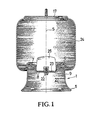
- the air spring according to FIG. 1 has an air spring bellows 24 designed as a rotationally symmetrical rubber bag which can be filled with air and which is to be connected to a vehicle frame (not shown) via an upper knurled steel plate 17 as a force introduction element.
- a convex, round-shaped base 23 made of steel is vulcanized, which carries a rubber buffer 25 as a stop toward the interior of the air bellows 24.
- the bottom 23 is convex on its underside and lies in a form-fitting manner in a correspondingly concave-shaped upper trough bottom of a plunger 1 and is screwed to it by means of a bolt 22 in a force-locking manner.
- the plunger 1 is a cup-shaped, rotationally symmetrical deep-drawn part made of steel.
- the essentially cylindrical plunger jacket 9 is slightly conical in the lower foot region 5 and then flanged in a semicircle inwards. Bores in the flanged edge provide a connection to the plate-shaped end of an air spring support arm (not shown).
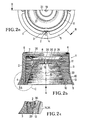
- the plunger arrangement according to the invention illustrated in FIGS. 2a to 2c is intended for use with an essentially identical air spring bellows arrangement 17, 23, 24, 25.
- the approximately pot-shaped outer plunger 1 has four 90 o arranged offset radially inwardly projecting and on over the entire height of the plunger piston skirt 9 extending reinforcing ribs. 2
- depressions 4 are provided for receiving threaded bolts (not shown) for connection to the support arm plate (not shown).
- the essentially cylindrical plunger jacket 9 merges at the top into a rounded, essentially semi-circular plunger rim 6, which is followed diagonally radially inward by a substantially frustoconical trough section 7 with an essentially flat trough bottom 8 to form an essentially frustoconical trough 27. in which the covex bottom 23 can be received in a form-fitting manner.
- the plunger jacket 9 has a slight inclination (eg ⁇ 1 °) with respect to the vertical S and widens conically outwards in its lower foot region 5 in an arc 10 of a wide radius (eg ⁇ 100 mm).
- a support body 11 designed as a particularly hollow truncated cone is positioned. Its ring-shaped foot region 12 is provided on its outside with, for example, a circumferential locking rib 13, which can snap into corresponding recesses 14 on the inside of the foot regions 3 of the four reinforcing ribs 2.
- the catch recesses 14, seen from below initially have an insertion bevel 29 which merges into a slight undercut 34, to which in turn an abutment edge 30 for the top of the catch rib 13 is directed upwards connects.
- this latching or snap connection 13, 14 the two parts, plunger 1 and support body 11, can be firmly but releasably connected to one another in a positive manner and supported against one another in the foot regions 3, 12 towards the outside and upwards.
- the inclination of the inner surface 15 of the support body jacket 33 is so much greater than the inclination of its outer surface 16 that the annular cross-sectional area F of the support body 11 remains the same at any height of the frustoconical support body 11.
- the base plate 18 has an opening 19 which is coaxial with the opening 20 of the trough base 8, through which the bolt 22 (not shown here) for connecting the two parts 1, 11 of the two-part plunger arrangement to the base 23 of the air bellows 24 can be passed.
- the base plate 18 is formed in the vicinity of the opening 19 in a concave, resilient manner, so that a flat cavity 36 remains free towards the trough bottom 8, which is somewhat reduced to the bottom when the bolt 22 is tightened in the rubber buffer 25. Due to the flat annular support between the outer plunger 1 and the support body 11 arranged in its interior 27, the trough 26 surrounded by the trough section 7 forms a type of double cone in the upper region of the outer plunger 1 and the support body 11.
- the latter has a reinforcement 31 in the central region.
- the underside 32 of the base plate 18 merges in an arc 29 with a relatively wide radius into the inner surface 15 of the truncated cone-shaped support body shell 33. This ensures a maximum degree of security against tearing out of the base plate 18 when it is pulled.
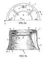
- FIG. 3a and 3b illustrate another embodiment of a plunger 1, in this case without the support body 2, from direction A of FIG. 3b or in section B-B of FIG. 3a.
- the plunger 1 has additional radially inward-pointing stiffening ribs 37 distributed symmetrically to the reinforcing ribs 2 over the circumference, each of which fills the width of the entire space between the plunger jacket 9 and the trough section 7 and to increase the section modulus of the plunger 1 to lead.
- the stiffening ribs 37 are also adapted to the contour of the outer surface 16 of the support body jacket 33, so that the plunger 1 can be supported on the outer circumference of the support body 11 via the stiffening ribs 37.
- the depressions 4 are not provided with a thread, as in the embodiment according to FIG. 2a-c. In this case, self-tapping screws are used for the connection to the support arm plate.
- the support body 11 has reinforcing ribs 39 which are distributed over the circumference of the support body shell 33 and project radially outwards and in which end-side recesses 40 for receiving bolts for connection with the air suspension bracket are provided.
- the plunger 1 closes with its foot area 5 in a form-fitting manner on the foot area 41 of the amplifier ribs.
- the system is supported by the external pressure exerted by the air bellows 24 when it rolls over.
- Plunger 1 and support body 11 are detachably connected to one another only in the region of the trough base 8 and the base plate 18 during assembly on the base 23 of the air bellows 24.
- the base plate 18 of the support body 11 is slightly concave, so that it is supported on the underside 28 of the trough base 8 of the plunger 1 by a central ring region immediately surrounding its opening 19.
- the support body jacket 33 is extended and widened beyond the base plate 18 to form a support ring 41.
- the end face of the support ring 41 lies in an outer ring area on the underside 28 of the trough bottom 8.
- the plunger jacket 9 corresponding to the embodiment according to FIGS. 3a and 3b is provided with stiffening ribs 37 pointing radially inwards.
Landscapes
- Engineering & Computer Science (AREA)
- Mechanical Engineering (AREA)
- General Engineering & Computer Science (AREA)
- Fluid-Damping Devices (AREA)
- Vehicle Body Suspensions (AREA)
- Reciprocating Pumps (AREA)
- Pistons, Piston Rings, And Cylinders (AREA)
- Devices For Use In Laboratory Experiments (AREA)
- Massaging Devices (AREA)
Priority Applications (2)
| Application Number | Priority Date | Filing Date | Title |
|---|---|---|---|
| AT89112535T ATE98750T1 (de) | 1988-07-20 | 1989-07-08 | Tauchkolbenanordnung. |
| CA 611730 CA1327054C (fr) | 1989-07-08 | 1989-09-18 | Systeme a piston-plongeur |
Applications Claiming Priority (2)
| Application Number | Priority Date | Filing Date | Title |
|---|---|---|---|
| DE3824542A DE3824542A1 (de) | 1988-07-20 | 1988-07-20 | Tauchkolbenanordnung |
| DE3824542 | 1988-07-20 |
Publications (3)
| Publication Number | Publication Date |
|---|---|
| EP0351678A2 true EP0351678A2 (fr) | 1990-01-24 |
| EP0351678A3 EP0351678A3 (en) | 1990-12-27 |
| EP0351678B1 EP0351678B1 (fr) | 1993-12-15 |
Family
ID=6359082
Family Applications (1)
| Application Number | Title | Priority Date | Filing Date |
|---|---|---|---|
| EP89112535A Expired - Lifetime EP0351678B1 (fr) | 1988-07-20 | 1989-07-08 | Dispositif à piston |
Country Status (5)
| Country | Link |
|---|---|
| US (1) | US4890823A (fr) |
| EP (1) | EP0351678B1 (fr) |
| AT (1) | ATE98750T1 (fr) |
| DE (2) | DE3824542A1 (fr) |
| HU (1) | HU207014B (fr) |
Cited By (10)
| Publication number | Priority date | Publication date | Assignee | Title |
|---|---|---|---|---|
| EP0446476A1 (fr) * | 1990-03-15 | 1991-09-18 | Continental Aktiengesellschaft | Piston de déroulage pour le soufflet roulant d'un ressort pneumatique à soufflet roulant |
| EP0546385A1 (fr) * | 1991-12-13 | 1993-06-16 | Continental Aktiengesellschaft | Ressort pneumatique pour véhicules avec un soufflet élastomèrique |
| EP0647795A1 (fr) * | 1993-10-11 | 1995-04-12 | Psa Sistemi Antivibranti S.P.A. | Piston pour ressorts pneumatiques, notamment pour les suspensions de véhicules |
| DE19702155A1 (de) * | 1996-05-07 | 1997-11-13 | Sauer Achsenfab | Tauchkolbenanordnung |
| EP0864453A1 (fr) * | 1997-03-15 | 1998-09-16 | BPW Bergische Achsen Kommanditgesellschaft | Ressort pneumatique pour essieux à suspension pneumatique |
| WO2008031784A1 (fr) * | 2006-09-14 | 2008-03-20 | Contitech Luftfedersysteme Gmbh | Soufflet tubulaire à éléments en plastique utilisable dans des véhicules utilitaires |
| EP2093082A1 (fr) | 2008-02-21 | 2009-08-26 | BPW Bergische Achsen KG | Suspension pneumatique pour un axe de véhicule à suspension pneumatique |
| WO2013156190A1 (fr) * | 2012-04-18 | 2013-10-24 | Contitech Luftfedersysteme Gmbh | Piston dérouleur pour soufflet de suspension pneumatique |
| DE102014108701A1 (de) * | 2014-06-20 | 2015-12-24 | Radkersburger Metallwarenfabrik Gmbh | Abrollkolben für eine Luftfeder |
| DE10149057B4 (de) * | 2001-10-05 | 2021-05-12 | Bpw Bergische Achsen Kg | Tauchkolben für eine Luftfeder |
Families Citing this family (17)
| Publication number | Priority date | Publication date | Assignee | Title |
|---|---|---|---|---|
| US5060916A (en) * | 1988-07-20 | 1991-10-29 | Otto Sauer Achsenfabrik Keilberg | Plunger piston system |
| DE4006480A1 (de) * | 1990-03-02 | 1991-09-05 | Continental Ag | Rollbalg-luftfeder mit einem schlauchrollbalg aus elastomerem werkstoff |
| DE4201629C1 (fr) * | 1992-01-22 | 1993-07-15 | Otto Sauer Achsenfabrik Keilberg, 8751 Bessenbach, De | |
| US5535994A (en) * | 1993-11-30 | 1996-07-16 | The Goodyear Tire & Rubber Company | Composite air spring piston |
| DE50006950D1 (de) * | 1999-07-07 | 2004-08-05 | Phoenix Ag | Luftfederanordnung |
| US6386524B1 (en) | 2000-02-15 | 2002-05-14 | Bfs Diversified Products, Llc | Pedestal mounted full reservoir air spring piston |
| US7104561B1 (en) * | 2000-03-14 | 2006-09-12 | Meritor Hvs Limited | Air spring |
| DE102004031873B3 (de) * | 2004-04-22 | 2005-11-17 | Zf Friedrichshafen Ag | Abrollrohr für einen Luftfederrollbalg |
| US7500659B2 (en) * | 2005-04-07 | 2009-03-10 | Bfs Diversified Products, Llc | Air spring assembly and method |
| US20090200717A1 (en) * | 2008-02-08 | 2009-08-13 | Veyance Technologies, Inc. | Air spring piston |
| US8231113B2 (en) * | 2008-06-05 | 2012-07-31 | Firestone Industrial Products Company, Llc | Gas spring assembly and spacer |
| US8498773B2 (en) * | 2010-05-20 | 2013-07-30 | GM Global Technology Operations LLC | Stability enhancing system and method for enhancing the stability of a vehicle |
| US9212717B2 (en) * | 2011-06-30 | 2015-12-15 | Firestone Industrial Products Company LLC | Gas spring end member as well as gas spring assembly including same |
| DE102015108519B3 (de) * | 2015-05-29 | 2016-07-28 | Saf-Holland Gmbh | Stützeinheit |
| CN109844356B (zh) * | 2016-10-17 | 2021-08-10 | 住友电气工业株式会社 | 空气弹簧和转向架 |
| DE102019201518A1 (de) * | 2019-02-06 | 2020-08-06 | Ebert-Consulting Gmbh | Fahrzeugstarrachse und Verfahren zu deren Herstellung |
| CN115435034A (zh) * | 2022-08-03 | 2022-12-06 | 安徽红桥金属制造有限公司 | 一种膜式空气弹簧缸体 |
Family Cites Families (9)
| Publication number | Priority date | Publication date | Assignee | Title |
|---|---|---|---|---|
| GB964138A (en) * | 1961-12-22 | 1964-07-15 | Firestone Tire & Rubber Co | Air springs for suspension systems and bellows therefor |
| DE6931018U (de) * | 1969-02-13 | 1971-04-22 | Gomma Antivibranti Applic | Daempfungsvorrichtung fuer luftfedern. |
| GB1248025A (en) * | 1970-05-06 | 1971-09-29 | Orszagos Gumiipari Vall | A rolling bellows type air spring |
| SE7605467L (sv) * | 1975-05-17 | 1976-11-18 | Plessey Handel Investment Ag | Anordning for att halla ett fordon vagrett |
| SU839745A2 (ru) * | 1979-09-17 | 1981-06-23 | Брянский Институт Транспортногомашиностроения | Пневматический упругий элементпОдВЕСКи ТРАНСпОРТНОгО СРЕдСТВА |
| US4506910A (en) * | 1982-09-21 | 1985-03-26 | Granning Suspensions, Inc. | Automotive vehicle suspension |
| US4784376A (en) * | 1987-06-17 | 1988-11-15 | The Firestone Tire & Rubber Company | End cap assembly for air spring |
| US4787606A (en) * | 1987-06-17 | 1988-11-29 | The Firestone Tire & Rubber Company | Beadless air spring |
| IT1205188B (it) * | 1987-06-26 | 1989-03-15 | Pirelli | Miglioramenti nelle molle ad aria |
-
1988
- 1988-07-20 DE DE3824542A patent/DE3824542A1/de active Granted
- 1988-09-09 US US07/242,412 patent/US4890823A/en not_active Expired - Fee Related
-
1989
- 1989-07-08 EP EP89112535A patent/EP0351678B1/fr not_active Expired - Lifetime
- 1989-07-08 DE DE89112535T patent/DE58906416D1/de not_active Expired - Lifetime
- 1989-07-08 AT AT89112535T patent/ATE98750T1/de not_active IP Right Cessation
- 1989-07-20 HU HU893686A patent/HU207014B/hu unknown
Cited By (14)
| Publication number | Priority date | Publication date | Assignee | Title |
|---|---|---|---|---|
| EP0446476A1 (fr) * | 1990-03-15 | 1991-09-18 | Continental Aktiengesellschaft | Piston de déroulage pour le soufflet roulant d'un ressort pneumatique à soufflet roulant |
| EP0546385A1 (fr) * | 1991-12-13 | 1993-06-16 | Continental Aktiengesellschaft | Ressort pneumatique pour véhicules avec un soufflet élastomèrique |
| EP0647795A1 (fr) * | 1993-10-11 | 1995-04-12 | Psa Sistemi Antivibranti S.P.A. | Piston pour ressorts pneumatiques, notamment pour les suspensions de véhicules |
| DE19702155C2 (de) * | 1996-05-07 | 2002-10-02 | Sauer Achsenfab | Tauchkolbenanordnung |
| DE19702155A1 (de) * | 1996-05-07 | 1997-11-13 | Sauer Achsenfab | Tauchkolbenanordnung |
| EP0864453A1 (fr) * | 1997-03-15 | 1998-09-16 | BPW Bergische Achsen Kommanditgesellschaft | Ressort pneumatique pour essieux à suspension pneumatique |
| DE19710849A1 (de) * | 1997-03-15 | 1998-09-24 | Bpw Bergische Achsen Kg | Luftfeder für Luftfederachsen |
| DE19710849B4 (de) * | 1997-03-15 | 2009-04-09 | Bpw Bergische Achsen Kg | Luftfeder für Luftfederachsen |
| DE10149057B4 (de) * | 2001-10-05 | 2021-05-12 | Bpw Bergische Achsen Kg | Tauchkolben für eine Luftfeder |
| WO2008031784A1 (fr) * | 2006-09-14 | 2008-03-20 | Contitech Luftfedersysteme Gmbh | Soufflet tubulaire à éléments en plastique utilisable dans des véhicules utilitaires |
| EP2093082A1 (fr) | 2008-02-21 | 2009-08-26 | BPW Bergische Achsen KG | Suspension pneumatique pour un axe de véhicule à suspension pneumatique |
| DE102008010469A1 (de) | 2008-02-21 | 2009-08-27 | Bpw Bergische Achsen Kg | Luftfeder für eine luftgefederte Fahrzeugachse |
| WO2013156190A1 (fr) * | 2012-04-18 | 2013-10-24 | Contitech Luftfedersysteme Gmbh | Piston dérouleur pour soufflet de suspension pneumatique |
| DE102014108701A1 (de) * | 2014-06-20 | 2015-12-24 | Radkersburger Metallwarenfabrik Gmbh | Abrollkolben für eine Luftfeder |
Also Published As
| Publication number | Publication date |
|---|---|
| ATE98750T1 (de) | 1994-01-15 |
| HU207014B (en) | 1993-03-01 |
| DE58906416D1 (de) | 1994-01-27 |
| EP0351678B1 (fr) | 1993-12-15 |
| US4890823A (en) | 1990-01-02 |
| DE3824542C2 (fr) | 1990-09-06 |
| EP0351678A3 (en) | 1990-12-27 |
| HUT53948A (en) | 1990-12-28 |
| DE3824542A1 (de) | 1990-01-25 |
Similar Documents
| Publication | Publication Date | Title |
|---|---|---|
| EP0351678B1 (fr) | Dispositif à piston | |
| DE60012394T2 (de) | Nichtmetallische Zwischenplatte für eine Luftfeder | |
| DE69703496T2 (de) | Lager für ein achsenaufhängungssystem | |
| DE69334210T2 (de) | Achsaufhängungssystem | |
| DE69211715T2 (de) | Dämpfendes und abgefedertes aufhängungssystem | |
| EP0446476B1 (fr) | Piston de déroulage pour le soufflet roulant d'un ressort pneumatique à soufflet roulant | |
| EP2605923B1 (fr) | Jambe de force a ressort pneumatique avec le montage souple du piston | |
| DE3346665A1 (de) | Elastisches lager mit zwangsfuehrung | |
| EP0864453A1 (fr) | Ressort pneumatique pour essieux à suspension pneumatique | |
| EP2903838B1 (fr) | Unité de direction | |
| DE102005026314C5 (de) | Tauchkolben aus Kunststoff für eine Luftfeder | |
| DE69519673T2 (de) | Dämpfungsvorrichtung für kraftfahrzeugstabilisatoren und verfahren zu ihrer befestigung | |
| DE102009030633A1 (de) | Achseinbindung für gefederte Fahrzeugachsen sowie Platte zum Einbinden einer Fahrzeugachse | |
| EP1586789A1 (fr) | Support élastique pour une cabine de véhicule | |
| EP1110010A1 (fr) | Dispositif d'amortissement pneumatique | |
| DE102018205215B4 (de) | Blattfedereinrichtung für ein Fahrzeug, Fahrwerk mit einer solchen Blattfedereinrichtung sowie ein Verfahren zum Herstellen einer solchen Blattfedereinrichtung und/oder eines solchen Fahrwerks | |
| EP1294999B1 (fr) | Assemblage du type a ciseaux avec corps d'assemblage pour le support de toit d'une tente pliante | |
| DE102005031939B4 (de) | Schwingungsdämpfer mit Zuganschlagfeder | |
| DE19524511C2 (de) | Aufhängung für Kompressoren | |
| EP1036677B1 (fr) | Suspension de roue pour un véhicule automobile | |
| DE29503151U1 (de) | Schwingungstilger | |
| EP2402180B1 (fr) | Axe de véhicule à suspension pneumatique | |
| DE102013113124A1 (de) | Luftfeder für eine luftgefederte Fahrzeugachse | |
| DE2626392A1 (de) | Unabhaengige radaufhaengung fuer kraftfahrzeuge | |
| DE69001184T2 (de) | Stabilisatoreinrichtung, mit dieser ausgeruestetes kraftfahrzeug und teilesatz zum einbau derselben in ein solches fahrzeug. |
Legal Events
| Date | Code | Title | Description |
|---|---|---|---|
| PUAI | Public reference made under article 153(3) epc to a published international application that has entered the european phase |
Free format text: ORIGINAL CODE: 0009012 |
|
| AK | Designated contracting states |
Kind code of ref document: A2 Designated state(s): AT BE CH DE ES FR GB GR IT LI LU NL SE |
|
| PUAL | Search report despatched |
Free format text: ORIGINAL CODE: 0009013 |
|
| AK | Designated contracting states |
Kind code of ref document: A3 Designated state(s): AT BE CH DE ES FR GB GR IT LI LU NL SE |
|
| 17P | Request for examination filed |
Effective date: 19910308 |
|
| 17Q | First examination report despatched |
Effective date: 19930408 |
|
| GRAA | (expected) grant |
Free format text: ORIGINAL CODE: 0009210 |
|
| AK | Designated contracting states |
Kind code of ref document: B1 Designated state(s): AT BE CH DE ES FR GB GR IT LI LU NL SE |
|
| PG25 | Lapsed in a contracting state [announced via postgrant information from national office to epo] |
Ref country code: GR Free format text: LAPSE BECAUSE OF FAILURE TO SUBMIT A TRANSLATION OF THE DESCRIPTION OR TO PAY THE FEE WITHIN THE PRESCRIBED TIME-LIMIT Effective date: 19931215 Ref country code: ES Free format text: THE PATENT HAS BEEN ANNULLED BY A DECISION OF A NATIONAL AUTHORITY Effective date: 19931215 Ref country code: BE Effective date: 19931215 Ref country code: SE Effective date: 19931215 |
|
| REF | Corresponds to: |
Ref document number: 98750 Country of ref document: AT Date of ref document: 19940115 Kind code of ref document: T |
|
| REF | Corresponds to: |
Ref document number: 58906416 Country of ref document: DE Date of ref document: 19940127 |
|
| ITF | It: translation for a ep patent filed | ||
| GBT | Gb: translation of ep patent filed (gb section 77(6)(a)/1977) |
Effective date: 19940318 |
|
| ET | Fr: translation filed | ||
| PGFP | Annual fee paid to national office [announced via postgrant information from national office to epo] |
Ref country code: LU Payment date: 19940630 Year of fee payment: 6 |
|
| EPTA | Lu: last paid annual fee | ||
| PLBE | No opposition filed within time limit |
Free format text: ORIGINAL CODE: 0009261 |
|
| STAA | Information on the status of an ep patent application or granted ep patent |
Free format text: STATUS: NO OPPOSITION FILED WITHIN TIME LIMIT |
|
| 26N | No opposition filed | ||
| PG25 | Lapsed in a contracting state [announced via postgrant information from national office to epo] |
Ref country code: LU Free format text: LAPSE BECAUSE OF NON-PAYMENT OF DUE FEES Effective date: 19950708 |
|
| PGFP | Annual fee paid to national office [announced via postgrant information from national office to epo] |
Ref country code: CH Payment date: 19990722 Year of fee payment: 11 Ref country code: AT Payment date: 19990722 Year of fee payment: 11 |
|
| PG25 | Lapsed in a contracting state [announced via postgrant information from national office to epo] |
Ref country code: AT Free format text: LAPSE BECAUSE OF NON-PAYMENT OF DUE FEES Effective date: 20000708 |
|
| PG25 | Lapsed in a contracting state [announced via postgrant information from national office to epo] |
Ref country code: CH Free format text: LAPSE BECAUSE OF NON-PAYMENT OF DUE FEES Effective date: 20000731 Ref country code: LI Free format text: LAPSE BECAUSE OF NON-PAYMENT OF DUE FEES Effective date: 20000731 |
|
| REG | Reference to a national code |
Ref country code: CH Ref legal event code: PL |
|
| REG | Reference to a national code |
Ref country code: GB Ref legal event code: IF02 |
|
| PGFP | Annual fee paid to national office [announced via postgrant information from national office to epo] |
Ref country code: FR Payment date: 20020717 Year of fee payment: 14 |
|
| PGFP | Annual fee paid to national office [announced via postgrant information from national office to epo] |
Ref country code: GB Payment date: 20030702 Year of fee payment: 15 |
|
| PGFP | Annual fee paid to national office [announced via postgrant information from national office to epo] |
Ref country code: NL Payment date: 20030721 Year of fee payment: 15 |
|
| PG25 | Lapsed in a contracting state [announced via postgrant information from national office to epo] |
Ref country code: GB Free format text: LAPSE BECAUSE OF NON-PAYMENT OF DUE FEES Effective date: 20040708 |
|
| PG25 | Lapsed in a contracting state [announced via postgrant information from national office to epo] |
Ref country code: NL Free format text: LAPSE BECAUSE OF NON-PAYMENT OF DUE FEES Effective date: 20050201 |
|
| GBPC | Gb: european patent ceased through non-payment of renewal fee |
Effective date: 20040708 |
|
| PG25 | Lapsed in a contracting state [announced via postgrant information from national office to epo] |
Ref country code: FR Free format text: LAPSE BECAUSE OF NON-PAYMENT OF DUE FEES Effective date: 20050331 |
|
| NLV4 | Nl: lapsed or anulled due to non-payment of the annual fee |
Effective date: 20050201 |
|
| REG | Reference to a national code |
Ref country code: FR Ref legal event code: ST |
|
| PG25 | Lapsed in a contracting state [announced via postgrant information from national office to epo] |
Ref country code: FR Free format text: LAPSE BECAUSE OF NON-PAYMENT OF DUE FEES Effective date: 20030731 |
|
| PGFP | Annual fee paid to national office [announced via postgrant information from national office to epo] |
Ref country code: DE Payment date: 20080923 Year of fee payment: 20 |
|
| PGFP | Annual fee paid to national office [announced via postgrant information from national office to epo] |
Ref country code: IT Payment date: 20080726 Year of fee payment: 20 |