EP0351817A2 - Verfahren und Gerät für eine drehbare Anzeige - Google Patents
Verfahren und Gerät für eine drehbare Anzeige Download PDFInfo
- Publication number
- EP0351817A2 EP0351817A2 EP89113238A EP89113238A EP0351817A2 EP 0351817 A2 EP0351817 A2 EP 0351817A2 EP 89113238 A EP89113238 A EP 89113238A EP 89113238 A EP89113238 A EP 89113238A EP 0351817 A2 EP0351817 A2 EP 0351817A2
- Authority
- EP
- European Patent Office
- Prior art keywords
- display
- information
- image information
- display means
- image
- Prior art date
- Legal status (The legal status is an assumption and is not a legal conclusion. Google has not performed a legal analysis and makes no representation as to the accuracy of the status listed.)
- Withdrawn
Links
Images


Classifications
-
- G—PHYSICS
- G09—EDUCATION; CRYPTOGRAPHY; DISPLAY; ADVERTISING; SEALS
- G09G—ARRANGEMENTS OR CIRCUITS FOR CONTROL OF INDICATING DEVICES USING STATIC MEANS TO PRESENT VARIABLE INFORMATION
- G09G1/00—Control arrangements or circuits, of interest only in connection with cathode-ray tube indicators; General aspects or details, e.g. selection emphasis on particular characters, dashed line or dotted line generation; Preprocessing of data
-
- G—PHYSICS
- G06—COMPUTING OR CALCULATING; COUNTING
- G06F—ELECTRIC DIGITAL DATA PROCESSING
- G06F1/00—Details not covered by groups G06F3/00 - G06F13/00 and G06F21/00
- G06F1/16—Constructional details or arrangements
- G06F1/1601—Constructional details related to the housing of computer displays, e.g. of CRT monitors, of flat displays
-
- G—PHYSICS
- G09—EDUCATION; CRYPTOGRAPHY; DISPLAY; ADVERTISING; SEALS
- G09G—ARRANGEMENTS OR CIRCUITS FOR CONTROL OF INDICATING DEVICES USING STATIC MEANS TO PRESENT VARIABLE INFORMATION
- G09G5/00—Control arrangements or circuits for visual indicators common to cathode-ray tube indicators and other visual indicators
- G09G5/36—Control arrangements or circuits for visual indicators common to cathode-ray tube indicators and other visual indicators characterised by the display of a graphic pattern, e.g. using an all-points-addressable [APA] memory
- G09G5/39—Control of the bit-mapped memory
- G09G5/391—Resolution modifying circuits, e.g. variable screen formats
-
- G—PHYSICS
- G06—COMPUTING OR CALCULATING; COUNTING
- G06F—ELECTRIC DIGITAL DATA PROCESSING
- G06F2200/00—Indexing scheme relating to G06F1/04 - G06F1/32
- G06F2200/16—Indexing scheme relating to G06F1/16 - G06F1/18
- G06F2200/161—Indexing scheme relating to constructional details of the monitor
- G06F2200/1611—CRT monitor
-
- Y—GENERAL TAGGING OF NEW TECHNOLOGICAL DEVELOPMENTS; GENERAL TAGGING OF CROSS-SECTIONAL TECHNOLOGIES SPANNING OVER SEVERAL SECTIONS OF THE IPC; TECHNICAL SUBJECTS COVERED BY FORMER USPC CROSS-REFERENCE ART COLLECTIONS [XRACs] AND DIGESTS
- Y10—TECHNICAL SUBJECTS COVERED BY FORMER USPC
- Y10S—TECHNICAL SUBJECTS COVERED BY FORMER USPC CROSS-REFERENCE ART COLLECTIONS [XRACs] AND DIGESTS
- Y10S248/00—Supports
- Y10S248/917—Video display screen support
Definitions
- the present invention relates to a method and apparatus for rotatable display apparatus, and more particularly to a display apparatus including rectangular screen having short and long sides capable of being rotated between a position in which the short side lies horizontally and a position in which the long side lies horizontally, and suitable for displaying images having different width/height ratio.
- a so-called filing system has been practically used in order to meet the requirements of rationalizing office works.
- a filing system a great amount of image data for images, documents and the like are read with an image scanner or the like and stored in a storage device such as an optical disk or magnetic disk so that the image data can be processed, retrieved, renewed, printed out and so on at any time as desired.
- image data to be stored in a storage device of such a filing system not only the document data having relatively similar formats, but also the mixed data of such documents with drawings, photographs and the like having relatively various types of formats, e.g., a longer height or width of image frame, are stored in many cases.
- a portion of the image data may be displayed outside of the screen or a blank portion may be present partially of the screen image.
- a display apparatus for use in a filing system adapted to be usable not only for documents but also for images is a large CRT of 17 inches or greater which can display thereon an image of about A-4 size. Therefore, the conventional method of switching the width/height ratio by manually rotating the display apparatus burdens an operator with large power, thereby deteriorating workability.
- a first object of the present invention is to provide a display apparatus capable of changing the width/height ratio of a display screen quickly and readily by driving the display device with driving means.
- a second object of the present invention is to provide a rotatable display apparatus having a tilting mechanism for tilting the display screen upward and downward.
- a third object of the present invention is to provide a rotatable display apparatus capable of releasing the tilting mechanism while the display device is rotated.
- a fourth object of the present invention is to provide a rotatable display apparatus capable of compensating a displacement of the screen image caused upon rotation of the display device.
- a fifth object of the present invention is to provide an information filing system capable of storing display formats of display data together with the display formats.
- a sixth object of the present invention is to provide an information filing system capable of automatically changing the display mode of the screen image on the display device in accordance with the stored display format of the display data.
- the rotatable display apparatus of this invention comprises a display device having a rectangular display screen; driving device for rotating said display device at least within a range allowing two opposite width/height ratios of said display screen; supporting device for rotatably supporting said display device; and posture controlling device for controlling the rotation posture of said display device with the aid of said driving device, whereby said display device is rotated in accordance with a width/height ratio of the image data to be displayed on the display screen, or alternatively said display device is rotated in accordance with an external command inputted from a keyboard or the like.
- image data as well as the control information such as display formats regarding the width/height ratio of the image data are stored in storage means, so that the width/height ratio of the display screen is automatically changed when the image data are displayed on the display device, in accordance with the control information. Therefore, the width/height ratio of the display screen is automatically made to follow a change in display format of the image data to be displayed, thereby considerably improving the workability of the filing system.
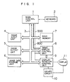
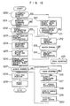
- Fig. 1 is a block diagram showing the internal structure of a filing system according to an embodiment of this invention.
- a main control unit 1 including a central processing unit (CPU) controls the input/output of image data and the operation of each device in the filing system.
- Image data are transferred via a system bus 3.
- a keyboard 2 is used by an operator to input a command to the main control unit 1 and input character information.
- An image input unit 4 e.g., an image scanner, reads image information on a medium in the form of binary signals.
- the image storage unit 6 files or stores image data therein, and is a storage drive such as an optical disk storage drive or magnetic disk storage drive.
- a main memory 7 stores programs for the main control unit 1 or is used as a work area for image data input/output or correction.
- An image display control unit 8 controls the display of image data on a display 11, e.g., to determine the display position, magnification, display format of image data.
- a signal for this control is sent via a character code bus 800 from the main control unit 1.
- Such a control signal includes the signals for guidance information to be displayed on a specified area of the display 11 for an operator.
- the display 11 visually displays image data.
- the display 11 in this embodiment has a rectangular display screen with a different height to width ratio, and is arranged to be capable of taking two positions by means of driving means such as a motor, one position being the shorter side lying horizontally and the other being the longer side lying horizontally.
- a display rotation control unit 9 controls the position of the display 11, a signal representative of the position being supplied from the main control unit 1 as one of a group of control signals 900.
- the display 11 has a housing 110 and a display device 112 (displaying means) with a rectangular display screen 111 made of a cathode ray tube (CRT).
- This display device 112 is rotatably supported ralative to the housing 110 such that a guide bearing 114 mounted on the housing 110 bears a support ring 113 (supporting means) in slidable relation therewith, and the support ring 113 holds the display device 112 at its center of gravity.
- a rotary shaft 115a concentrical to the center of rotation of the display device 112, a pulley 115b fixedly connected to the rotary shaft 115a and a roller 115d in slidable contact with the pulley 115 and driven by a motor 115c (driving means).
- the display device 112 With the rotational force exerted from the motor 115c, the display device 112 is rotated by a desired angle in the desired direction about the center of the display screen 111. If an excessive large external force against the rotation of the display device 112 is applied, the pulley 115b slips relative to the roller 115d to thereby avoid a possible trouble.
- a slit disk 116 (rotary position detecting means) having a slit 116a formed at the circumferential outer periphery thereof is coaxially and fixedly connected to the rotary shaft 115a.
- the outer periphery of the slit disk 116 is arranged to pass along rotary position detecting switches 117 and 118 (rotary position detecting means) such as photocouplers which are fixedly mounted on the housing 110 at positions radially spaced by 90 degrees relative to the rotary shaft 115a.
- rotary position detecting switches 117 and 118 rotary position detecting means
- photocouplers which are fixedly mounted on the housing 110 at positions radially spaced by 90 degrees relative to the rotary shaft 115a.
- the position of the slit 116a which rotates as the rotary shaft 115a rotates is detected by the rotary position detecting switches 117 and 118 which output position detection signals 117a and 118a, so that the rotation state of the display device 112 can be recognized by the display rotation control unit 9.
- the support ring 113 supporting the display device 112 is eccentric in form such that the distance Ra from the rotation center of the display screen 111 to the ring on the longer side 111a is different from the distance Rb from the rotation center to the ring on the shorter side 111b. Therefore, the height H from the housing 110 to the bottom of the display screen 111 is the same for both two positions at which the longer side 111a and shorter side 111b each are set at the bottom.
- the display rotation control unit 9 is constructed of a rotation actuation control unit 901, timer 902, end position detecting circuit 903, error detecting circuit 904 and other circuit elements.
- the AND gate 905 is inputted with the width/height discrimination information (control information) to be described later and automatic rotation command AUTO, respectively supplied from the main control unit 1 via the system bus 3.
- the OR gate 906 is inputted with an output from the AND gate 905 and a rotation actuation command S supplied via the system bus 3.
- the rotation of the display 11 is effected by means of the rotation actuation control unit 901 and driver circuit 10, if the rotation actuation command S having a level "1" is supplied from the main control unit 1 upon manipulation of the keyboard 2 by an operator, or if the automatic rotation command AUTO and width/height discrimination information WH both having a level "1" are supplied at the same time.
- This embodiment therefore is arranged to be capable of selecting one of two modes, i.e., one mode wherein an operator can make the display 11 to rotate upon manipulation of the keyboard 2 at any time the operator desires, and the other mode wherein the display 11 can be rotated automatically in accordance with the width/height discrimination information WH indicating a longer height or longer width of respective image data fetched from the image storage unit 6.
- a forced stop command STOP can also be supplied from the main control unit 3 to the rotation actuation control unit 901 via the system bus 3, thereby allowing a forced rotation stop of the display 11 at a desired time.
- the timer 902 connected between the rotation actuation control unit 901 and driver circuit 10 is set with a predetermined limit time which is longer, by a certain time, than a time required for the driver circuit 10 to rotate the display 11 by 90 degrees. If the display 11 does not complete its rotation within the predetermined limit time after the time when the rotation actuation control unit 901 has instructed the driver circuit 10 to rotate the display 11, a time-over command 902a is supplied to the driver circuit 10, main control unit 1 and other necessary circuits to thereby stop the rotation of the display 11.
- the end position detection circuit 903 supplies display rotary position information 903 to the main control unit 1, rotation actuation control unit 901, error detection circuit 904 and other necessary circuits, in accordance with the position detection signals 117a and 118a supplied from the rotary position detection switches 117 and 118.
- the error detection circuit 904 discriminates error information 10a regarding the state of the motor 115c and the like supplied from the driver circuit 10 and sends the discriminated error information to the main control unit 1.
- the driver circuit 10 is also inputted with a rotation direction indication command 810a for the display 11 supplied from the main control unit 1 via a rotation direction register 810.
- the display 11 is rotated upon receipt of the rotation direction indication command 810a and an actuation command from the rotation actuation control unit 901.
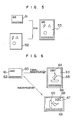
- Fig. 5 in the filing system of this embodiment, when the image data 52 stored in image storage means are displayed on the display 11, character data 51 are superposed which include guidance information for operator, function key definition, characters representative of mouse mode and the like.
- the character data 51 are magnified or reduced at a predetermined magnification/reduction factor, and the display position of the character data is determined, to thereby produce a mixed or superposed image 53.
- This image superposition will further be detailed below.
- Fig. 6 shows diagrams used for explaining the operation of displaying the contents of the character data 60 on a longer height display screen (display area) 63 and a longer width display screen (display area) 67.
- an image 65 of the image data is displayed on the screen at the same position, while the display 11 is physically rotated by 90 degrees.
- character information 61 of the character data 60 is displayed on the display screen 63 at an equal magnification factor to the character information 64, whereas it is displayed on the display screen 67 at a greater magnification factor after rotated by 90 degrees in the memory, as the character information 68.
- guidance information 62 e.g., for function keys, is displayed on the display screen 63 as the guidance information 66 and on the display screen 67 as the guidance information 69, respectively at different magnification factors and different display positions.
- the character data are superposed on the image 65 after being converted to a predetermined position and magnification factor, in accordance with a display mode defining the shape and dimension of a display area, the display position and the like.
- the image display control unit 8 includes a character bit map memory (BMM) 77 for storing character codes such as the guidance information 62 sent via the character code bus 800, and an image bit map memory (BMM) 81 for storing image data sent via the system bus 3.
- BMM character bit map memory
- BMM image bit map memory
- a character code sent via the character code bus 800 is temporarily stored in a latch (LT) 73 and thereafter sent to a buffer control unit 74.
- the buffer control unit 74 controls the data input/output of a rotation buffer 75 which temporarily stores character codes such as guidance information 62 for the purpose of rotating the character codes.
- a rotation control unit 76 outputs the data stored in the rotation buffer 75 through conversion of the memory storage addresses so as to display the data on the display by rotating by 90 degrees.
- a position detection unit 71 selects, in accordance with a signal of the control signal group 900 supplied from the main control unit 1 and representative of the display position, either a character code stored in the latch 73 or a character code rotated by 90 degrees and outputted from the rotation control unit 76, and stores the selected one in the character bit map memory (BMM) 77.
- a read-out circuit 78 reads at a predetermined timing, in accordance with a signal in the control signal group 900 supplied from the main control unit 1, character data from the character bit map memory (BMM) 77, to thereby determine the display position for the character code on the display.
- a display magnification factor conversion unit 79 converts the read-out character data at a predetermined magnification factor and outputs the converted character data.
- the image data sent from the system bus 3 are temporarily stored in a latch (LT) 80 and thereafter, stored in the image bit map memory (BMM) 81.
- LT latch
- BMM image bit map memory
- a mixing processing unit 82 mixes (superposes) an output from the character bit map memory (BMM) 77 with (upon) an output from the image bit map memory (BMM) 81, and outputs the result to the display 11.
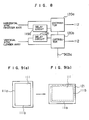
- the inventors of this invention found that a new problem was associated with the embodiment constructed as above, wherein a cathode ray tube was used as the display device 112 of the display 11, and the width/height ratio of the display screen 111 was changed by physically rotating the display device by 90 degrees. Specifically, upon rotation of the display 11, positional displacement of an image on the display screen 111 occured because of the adverse effects of earth magnetism and magnetic field generated from other peripheral apparatus. This positional displacement will be described with reference to Figs. 8, 9(a) and 9(b).
- An image on the display screen 111 may sometimes be displaced to, e.g., an upper right area 121 when the display screen 111 is rotated counterclockwise by 90 degrees from the position shown in Fig. 9(a) where the longer side 111a is set upright (upright type) to the position shown in Fig. 9(b) where the longer side 111a is set horizontal (lateral type).
- the display 11 is provided with delay circuits 119a and 119b at the signal paths of horizontal and vertical sync signals inputted to the display device 112, the delay time of delay circuits 119a and 119b being controllable externally.
- Distributors 120a and 120b selectively output either a delayed or not-delayed signal of each of the horizontal and vertical sync signals, in accordance with the rotary position information 903a of the display 11. If the image on the display screen 111 displaces to the upper right area as shown in Fig. 9(b), the positional displacement is compensated by advancing the display start position in the horizontal direction (corresponding to the longer side) and by lagging in the vertical direction (corresponding to the shorter side).
- a displacement offset value obtained when the display 11 is rotated by 90 degrees at the factory before delivery is set as such compensation quantity. If the compensation quantity differs from premises to premises where the display is installed due to differing power distribution facilities of the premises as well as due to differing apparatuses disposed around the display, the compensation quantity to be set may be actually measured.
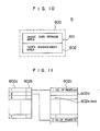
- a storage medium 600 such as an optical disk, magnetic disk or the like constituting the image data storage unit 6 includes an image data storage area 601 and an index management area 602.
- the image data storage area 601 stores the ordinary image data 52
- the index management area 602 stores the storage position, title and the like of the respective image data 52 in the image data storage area 601.
- the index management area 602 includes, as shown in Fig. 11, a title storage area 602a and a page pointer 602b, the title storage area 602a storing a title of a document made of a plurality of image data.
- the page pointer 602b stores the information representing a page number record area 602c in which the number of pages of a set of image data 52 given by a title is recorded.
- an image pointer 602d is recorded which indicates the storage position, in the image data storage area 601, of a set of image data of the associated document given by the title.
- a width/height information flag area 602e is provided in correspondence with each image pointer 602d.
- the width/height information flag area 602e stores the width/height discrimination information WH for discriminating whether the image data 52 indicated by the image pointer 602d is of an upright type or lateral type.
- the width/height discrimination information WH for discrimination between the upright type and lateral type is recorded beforehand when image data are registered. For instance, the image data for the upright type is given "1" and the image data for the lateral type is given "0" as the width/height discrimination information WH.
- the main control unit 1 Upon turning on the power, the main control unit 1 detects the present posture of the display device 112 based on the position detection signals 117a and 118a obtained by the end position detection circuit 903 and the rotary position detection switches 117 and 118 of the display control unit 9. If it is judged that the display device 112 is at an intermediate position between the upright and lateral positions, data for a predetermined rotation direction are forcibly set at the rotation direction register 810 and thereafter, a set of operations at step 1202 and following steps to be described later are executed to automatically set the display device at the upright posture or lateral posture.
- a mode is selected, in which mode an operator judges if the display device 112 of the display 11 is to be rotated or not and causes the width/height ratio of the display screen 111 to match the image data to be displayed.
- step 1201 it is checked if the operator has instructed to rotate the display device 112 by means of the keyboard 2 or a predetermined switch (not shown) (step 1201). If a rotation command is detected, the main control unit 1 supplies the actuation command S to the display rotation control unit 9.
- the rotation actuation control unit 901 of the display rotation control unit 9 makes the motor 115c operable with the aid of the driver circuit 10.
- the error detection circuit 904 checks to see if the error information 10a is being generated from the driver circuit 10 (step 1202). If the error information 10a is being generated, an error message is displayed on the display device 11 (step 1212), and an abnormal state of the driving system such as the motor 115c is checked (step 1213). If there is an abnormal state, the rotation operation is not executed (step 1215).
- the error information 10a is released (step 1214). Then, the present position information of the display device 112 is detected based on the display rotary position information 903a sent from the end position detection circuit, in accordance with the position detection signals 117a and 118a supplied from the rotary position detection switches 117 and 118 (step 1203).
- the main control unit 1 Upon receipt of the display rotary position information 903a, the main control unit 1 refers to the previous rotation direction stored in the rotation direction register 810 in the image display control unit 8, and based on both the information, determines the rotation direction and updates the contents of the rotation direction register 810 so as to set the determined rotation direction and thereafter supply the rotation direction indication command 810a to the driver circuit 10 (step 1204).
- the driver circuit 10 Upon receipt of the rotation direction indication command 810a, the driver circuit 10 starts rotating the motor 115c, and at the same time the rotation actuation control unit 901 causes the timer 902 to start operating (step 1205).
- the image display control unit 8 Simultaneously with the start of the rotation operation of the display device 112 in the predetermined direction by means of the motor 115c, the image display control unit 8 performs a set of rotation operations described above to automatically change the image layout, by transferring the guidance information 62 constituting the character information and the like from the latch (LT) 73 or the rotation control unit 76 to the character bit map memory 77.
- the guidance information 62 is rotated in the predetermined direction by 90 degrees so that the guidance information displayed at the lower portion of the display screen 60 shown in Fig. 6 is changed to the image displayed on the display screen 67 after the rotation thereof by 90 degrees.
- the distributors 120a and 120b optimize the delay conditions of the horizontal and vertical sync signals to be inputted to the display device 112, in accordance with the display rotary position information 903a, to thereby compensate the positional displacement due to the earth magnetism against the display screen (step 1206).
- the driver circuit 10 monitors the motor 115c (step 1207) and the timer 902 while the motor 115c rotates (step 1216). If a time-over command 902a is detected, it is assumed that the rotation operation of the display device 112 by means of the motor 115c has not been completed within a predetermined time limit because of certain reasons such as an external force. Then, a time-over message is generated (step 1217), the error information 10a is set (step 1218), an error message is displayed as system information G1 (step 1219), and the motor 115c is forcibly stopped (step 1220).
- the motor 115c stops normally prior to generating the time-over command 902a from the timer 902 at step 1207, it is confirmed if the objective posture of the display device 112 has been obtained by detecting the display rotary position information 903a supplied from the end position detection circuit 903 based on the position detection signal 117a or 118a supplied from the position detection switch 117 or 118 (step 1208). Thereafter, the timer 902 is reset (step 1209). A set of consecutive operations initiated by the operator intention has thus been completed for changing the width/height ratio of the display screen 111 by rotating the display device 112 by 90 degrees.
- the support ring is eccentric relative to the rotation center of the display device 112, the height H from the housing 110 to the displayed guidance information 62 does not change before and after the rotation of the display device 112.
- the position of the guidance information 62 displayed on the display screen 111 is thus unchanged, before and after the layout change, relative to an operator taking a predetermined posture relative to the housing 110.
- the main control unit 1 Upon selection by the operator the automatic rotation mode through manipulation of the keyboard 2 or a predetermined switch (not shown), the main control unit 1 supplies to the display rotation control unit 9 the automatic rotation command AUTO which is latched as a signal of "1" level to the one input terminal of the AND gate 905.
- step 1210) if the operator instructs optional image data 52 to be read from the image storage unit 6 and displayed on the display 11, detected are the image data 52 and width/height discrimination information WH previously stored therewith (step 1210).
- the main control unit 1 sets the width/height discrimination information WH at "0" level to thereby maintain the display device 112 stationary. If the width/height discrimination information WH is different from the previous, the width/height discrimination information WH of "1" level is supplied to the display rotation control unit 11 to accordingly make the AND gate 901 output a signal of "1" level and start the operation at step 1202 and following steps by the rotation actuation control unit 901 and the like as described previously (step 1211).
- the width/height ratio of the display screen 111 is automatically changed to have an optimum one for the particular image data 52 while rotating the display device 112.
- the layout of, and the display position as viewed from the operator of, the guidance information 62 such as error messages, help messages or the like, are maintained always constant irrespective of the rotation of the display screen 111.
- the width/height ratio of the display screen 111 is changed while rotating the display screen 112, in accordance with the operator intention, or automatically in accordance with a change of the width/height ratio of the image data 52 to be displayed. Therefore, even if a large sized and heavy cathode ray tube is used as the display device 112, a heavy burden is not charged with the operator to thus considerably improve the workability of the apparatus when compared to a conventional manual operation.
- the layout of, and the display position as viewed from the operator of, the guidance information 62 such as error messages, help messages or the like, are maintained always constant irrespective of the rotation of the display screen 111, resulting in an easy and comfortable operation.
- Fig. 13 is a side view partially in cross section of another embodiment of the display 13 according to the present invention.
- Figs. 14, 15 and 16 are sectional views taken along lines A-A, B-B and C-C, respectively.
- a rotary ring 1303 is mounted along the plane of the center of gravity of a display device 1302 made of a cathode ray tube and the like and having a rectangular display screen 1301.
- the rotary ring 1303 is rotatably supported by a plurality of guide rollers 1306 and 1307 disposed within upper and lower ring cases 1304 and 1305 so as to be rotatable in the plane parallel with the display screen 1301.
- a plurality of rotary position detection switches 1312 and 1313 are fixedly connected within the upper and lower ring cases 1304 and 1305, the switches being spaced apart relative to one another by 90 degrees in the radial direction of the rotary ring 1303.
- the switches are actuated by a projection (not shown) formed on the rotary ring 1303 so that the rotation posture of the display device 1302 can be detected.
- the upper and lower ring cases 1304 and 1305 are supported on a tilt base 1318 via tilt shafts 1314 and 1315 and support arms 1316 and 1317.
- the display device 1302 supported by the upper and lower rings 1304 and 1305 can be tilted up and down within a predetermined tilt range through manual operation by an operator.
- cam portions 1303a and 1303b formed on the peripheral portion of the rotary ring 1303 are cam portions 1303a and 1303b gradually projecting from the rotary ring at the positions corresponding to the corner of the display screen 1301 between the tilt shafts 1314 and 1315.
- Posture control rollers 1319 and 1320 are mounted on the support arms 1316 and 1317.
- the portion having a larger radius such as the corner of the rectangular display screen 1301a may abut on another member such as the housing.
- the cam portion 1303a or 1303b is arranged to become in slide contact with the posture control roller 1319 or 1320 while rotating the display device 1302. Therefore, even if the display device is tilted up or down, the front or back end portion of the display device 1302 is lifted up during the rotation to thereby automatically make the tilt angle zero and avoid a possible trouble as described above.
- the rubber roller 1310 in slide contact with the rotary ring 1303 slips so that the damage of the motor 1311 or other components due to over load can be avoided beforehand.
- the width/height ratio of the display screen 1301 can be automatically changed by physically rotating the display device 1302, and the display screen 1301 can be easily tilted by the operator by tilting up or down the display device 1302. Therefore, the workability can be improved further. Furthermore, the posture of the display device 1302 tilted up or down can be automatically corrected while rotating the display device 1302, so that the collision against another member can be avoided reliably, to thus realize a safe and comfortable work environment.
- the display device not only a cathode ray tube, but also other general image display devices such as a liquid crystal display and a plasma display may be used.
Landscapes
- Engineering & Computer Science (AREA)
- Theoretical Computer Science (AREA)
- Computer Hardware Design (AREA)
- Physics & Mathematics (AREA)
- General Physics & Mathematics (AREA)
- General Engineering & Computer Science (AREA)
- Human Computer Interaction (AREA)
- Radar, Positioning & Navigation (AREA)
- Remote Sensing (AREA)
- Controls And Circuits For Display Device (AREA)
- Digital Computer Display Output (AREA)
- Processing Or Creating Images (AREA)
- Devices For Indicating Variable Information By Combining Individual Elements (AREA)
Applications Claiming Priority (2)
| Application Number | Priority Date | Filing Date | Title |
|---|---|---|---|
| JP63182128A JP2612044B2 (ja) | 1988-07-21 | 1988-07-21 | 電子ファイル装置 |
| JP182128/88 | 1988-07-21 |
Publications (2)
| Publication Number | Publication Date |
|---|---|
| EP0351817A2 true EP0351817A2 (de) | 1990-01-24 |
| EP0351817A3 EP0351817A3 (de) | 1991-07-31 |
Family
ID=16112818
Family Applications (1)
| Application Number | Title | Priority Date | Filing Date |
|---|---|---|---|
| EP19890113238 Withdrawn EP0351817A3 (de) | 1988-07-21 | 1989-07-19 | Verfahren und Gerät für eine drehbare Anzeige |
Country Status (3)
| Country | Link |
|---|---|
| US (1) | US5134390A (de) |
| EP (1) | EP0351817A3 (de) |
| JP (1) | JP2612044B2 (de) |
Cited By (7)
| Publication number | Priority date | Publication date | Assignee | Title |
|---|---|---|---|---|
| EP0544155A1 (de) * | 1991-11-25 | 1993-06-02 | Nsm Aktiengesellschaft | Schwenkbare Bildschirmröhre für Video-Spielgeräte |
| US5329289A (en) * | 1991-04-26 | 1994-07-12 | Sharp Kabushiki Kaisha | Data processor with rotatable display |
| EP1382897A3 (de) * | 2002-07-16 | 2004-12-15 | Samsung Electronics Co., Ltd. | Bildschirmtragevorrichtung |
| WO2004111932A1 (ja) * | 2003-06-10 | 2004-12-23 | Fujitsu Limited | 画像登録装置、表示制御装置、画像サーバ |
| EP2329700A4 (de) * | 2008-09-25 | 2012-08-15 | Coby Electronics Corp | Andockstation mit drehmechanismus |
| EP3106962A1 (de) * | 2015-06-04 | 2016-12-21 | Samsung Electronics Co., Ltd. | Anzeigevorrichtung und ansteuerungsverfahren der anzeigevorrichtung |
| EP3444798A1 (de) * | 2017-08-16 | 2019-02-20 | Vestel Elektronik Sanayi ve Ticaret A.S. | Anzeigesystem, verfahren und computerprogramm zum steuern einer elektronischen anzeige |
Families Citing this family (81)
| Publication number | Priority date | Publication date | Assignee | Title |
|---|---|---|---|---|
| JP2595966Y2 (ja) | 1991-12-07 | 1999-06-02 | テクモ株式会社 | モニター内蔵装置 |
| US5537127A (en) * | 1992-06-30 | 1996-07-16 | Kabushiki Kaisha Toshiba | Image monitor system console |
| JP3227218B2 (ja) * | 1992-09-11 | 2001-11-12 | キヤノン株式会社 | 情報処理装置 |
| US5668570A (en) * | 1993-06-29 | 1997-09-16 | Ditzik; Richard J. | Desktop computer with adjustable flat panel screen |
| US5774233A (en) * | 1993-12-09 | 1998-06-30 | Matsushita Electric Industrial Co., Ltd. | Document image processing system |
| JP3322021B2 (ja) * | 1994-08-22 | 2002-09-09 | カシオ計算機株式会社 | 情報機器 |
| JP3707084B2 (ja) * | 1994-10-31 | 2005-10-19 | ソニー株式会社 | 表示装置及び表示方法 |
| JPH08289229A (ja) * | 1995-04-11 | 1996-11-01 | Seiichi Yashima | テレビ受像機の収納ラック |
| US5745097A (en) * | 1995-11-08 | 1998-04-28 | Apple Computer, Inc. | Apparatus and method for automatic image display alignment |
| US5910882A (en) * | 1995-11-14 | 1999-06-08 | Garmin Corporation | Portable electronic device for use in combination portable and fixed mount applications |
| US6137468A (en) * | 1996-10-15 | 2000-10-24 | International Business Machines Corporation | Method and apparatus for altering a display in response to changes in attitude relative to a plane |
| USD396845S (en) | 1996-12-19 | 1998-08-11 | Xs Technologies, Inc. | Uninterruptible power supply control and display module |
| USD403662S (en) * | 1996-12-19 | 1999-01-05 | Xs Technologies, Inc. | Uninterruptible power supply |
| EP0918491B1 (de) * | 1997-01-24 | 2003-06-04 | Koninklijke Philips Electronics N.V. | Bildanzeigevorrichtung |
| US5793627A (en) * | 1997-02-10 | 1998-08-11 | Xs Technologies, Inc | Uninterruptible power supply system with removable front panel display and control module |
| TW321414U (en) * | 1997-05-07 | 1997-11-21 | Amtran Technology Co Ltd | Pivot-rotation device of flat-display panel |
| US5973734A (en) | 1997-07-09 | 1999-10-26 | Flashpoint Technology, Inc. | Method and apparatus for correcting aspect ratio in a camera graphical user interface |
| US5973664A (en) * | 1998-03-19 | 1999-10-26 | Portrait Displays, Inc. | Parameterized image orientation for computer displays |
| JP2000076380A (ja) * | 1998-08-31 | 2000-03-14 | Casio Comput Co Ltd | 手書き文字入力装置及び記憶媒体 |
| US6343006B1 (en) | 1998-11-20 | 2002-01-29 | Jerry Moscovitch | Computer display screen system and adjustable screen mount, and swinging screens therefor |
| DE19983832T1 (de) | 1998-12-23 | 2001-11-29 | Jerry Moscovitch | Computer-Anzeigebildschirmsystem und verstellbare Bildschirmhalterung sowie schwenkbare Bildschirme dafür |
| US6317141B1 (en) | 1998-12-31 | 2001-11-13 | Flashpoint Technology, Inc. | Method and apparatus for editing heterogeneous media objects in a digital imaging device |
| JP2000315132A (ja) * | 1999-04-30 | 2000-11-14 | Sony Corp | 情報処理装置及びその方法並びに媒体 |
| KR100534672B1 (ko) * | 1999-05-26 | 2005-12-08 | 삼성전자주식회사 | 온 스크린 디스플레이를 피벗시키기 위한 기능을 갖는 영상표시장치 |
| JP4545884B2 (ja) * | 1999-07-22 | 2010-09-15 | キヤノン株式会社 | 情報処理装置及びその制御方法、コンピュータ可読メモリ |
| US6433791B2 (en) * | 1999-08-10 | 2002-08-13 | Smar Research Corporation | Displaceable display arrangement |
| US7162477B1 (en) | 1999-09-03 | 2007-01-09 | International Business Machines Corporation | System and method for web or file system asset management |
| US6704007B1 (en) * | 1999-09-27 | 2004-03-09 | Intel Corporation | Controlling displays for processor-based systems |
| JP2001156893A (ja) * | 1999-11-29 | 2001-06-08 | Nec Saitama Ltd | 通信機器の表示システム及び方法 |
| JP2001309398A (ja) * | 2000-04-18 | 2001-11-02 | Sony Corp | 画像表示装置及び画像表示装置の地磁気による画像の傾き補正方法 |
| US7023499B2 (en) * | 2001-09-21 | 2006-04-04 | Williams Cassandra S | Television receiver with motion sensor |
| JP2003241682A (ja) * | 2002-01-03 | 2003-08-29 | Samsung Electronics Co Ltd | ディスプレイ装置,ディスプレイ装置の回転位置検出装置,及びコンピュータ |
| US7324085B2 (en) | 2002-01-25 | 2008-01-29 | Autodesk, Inc. | Techniques for pointing to locations within a volumetric display |
| US7138997B2 (en) * | 2002-06-28 | 2006-11-21 | Autodesk, Inc. | System for physical rotation of volumetric display enclosures to facilitate viewing |
| US7839400B2 (en) * | 2002-01-25 | 2010-11-23 | Autodesk, Inc. | Volume management system for volumetric displays |
| US7554541B2 (en) * | 2002-06-28 | 2009-06-30 | Autodesk, Inc. | Widgets displayed and operable on a surface of a volumetric display enclosure |
| GB0209219D0 (en) * | 2002-04-23 | 2002-06-05 | Koninkl Philips Electronics Nv | Electronic device including a display |
| US7542052B2 (en) * | 2002-05-31 | 2009-06-02 | Hewlett-Packard Development Company, L.P. | System and method of switching viewing orientations of a display |
| KR20030095663A (ko) * | 2002-06-14 | 2003-12-24 | 삼성전자주식회사 | 트리플 윈도우 구현이 가능한 영상처리장치 및 그의구현방법 |
| US7952569B2 (en) * | 2002-08-08 | 2011-05-31 | Hewlett-Packard Development Company, L.P. | System and method of switching between multiple viewing modes in a multi-head computer system |
| US7882162B2 (en) * | 2002-08-08 | 2011-02-01 | Hewlett-Packard Development Company, L.P. | Rapid access to data on a powered down personal computer |
| US7209124B2 (en) * | 2002-08-08 | 2007-04-24 | Hewlett-Packard Development Company, L.P. | Multiple-position docking station for a tablet personal computer |
| US7426329B2 (en) * | 2003-03-06 | 2008-09-16 | Microsoft Corporation | Systems and methods for receiving, storing, and rendering digital video, music, and pictures on a personal media player |
| US20040201595A1 (en) * | 2003-04-11 | 2004-10-14 | Microsoft Corporation | Self-orienting display |
| CN1315361C (zh) * | 2003-06-09 | 2007-05-09 | 三星电子株式会社 | 显示器及其控制方法 |
| US20050140696A1 (en) * | 2003-12-31 | 2005-06-30 | Buxton William A.S. | Split user interface |
| US20050249435A1 (en) * | 2004-05-06 | 2005-11-10 | Rai Barinder S | Apparatuses and methods for rotating an image |
| US7082028B2 (en) * | 2004-07-08 | 2006-07-25 | Swivel It, Inc. | Rotatable computer display apparatus and method |
| KR100620372B1 (ko) * | 2004-08-18 | 2006-09-08 | 삼성전자주식회사 | 영상을 회전시키는 방법, 컴퓨터 및 저장매체 |
| GB0427548D0 (en) * | 2004-12-15 | 2005-01-19 | Ibm | Data processing system |
| US7908080B2 (en) | 2004-12-31 | 2011-03-15 | Google Inc. | Transportation routing |
| KR101090068B1 (ko) * | 2005-01-05 | 2011-12-07 | 삼성전자주식회사 | 회전검출장치와 이를 포함하는 디스플레이장치 및디스플레이시스템 |
| US20070204220A1 (en) * | 2006-02-27 | 2007-08-30 | Microsoft Corporation | Re-layout of network content |
| US9224145B1 (en) | 2006-08-30 | 2015-12-29 | Qurio Holdings, Inc. | Venue based digital rights using capture device with digital watermarking capability |
| US8096069B2 (en) * | 2006-09-06 | 2012-01-17 | The Invention Science Fund I, Llc | Repeatably displaceable emanating element display |
| TWI369669B (en) * | 2007-06-07 | 2012-08-01 | Lite On Technology Corp | Method for enabling a digital photo frame to automatically adjust a placement direction thereof, and digital photo frame applying the method |
| US8134577B2 (en) * | 2007-09-04 | 2012-03-13 | Lg Electronics Inc. | System and method for changing orientation of an image in a display device |
| JP5135007B2 (ja) * | 2008-03-10 | 2013-01-30 | オリンパスメディカルシステムズ株式会社 | カプセル誘導システム |
| USD612389S1 (en) * | 2008-04-23 | 2010-03-23 | Htc Corporation | Graphic user interface for a display screen |
| US8355031B2 (en) * | 2009-03-17 | 2013-01-15 | Harris Corporation | Portable electronic devices with adjustable display orientation |
| EP2755591B1 (de) | 2011-09-16 | 2020-11-18 | Auris Health, Inc. | System zur bildlichen darstellung der anatomie eines patienten auf einem beweglichen anzeigegerät |
| CN103019613A (zh) * | 2011-09-23 | 2013-04-03 | 鸿富锦精密工业(深圳)有限公司 | 基于Windows操作系统的自动旋转显示系统 |
| JP5981708B2 (ja) * | 2011-12-06 | 2016-08-31 | 株式会社タイトー | ゲーム機 |
| US9342170B2 (en) * | 2012-02-17 | 2016-05-17 | Sony Mobile Communications Inc. | Device and method for delaying adjustment of display content output on a display based on input gestures |
| WO2014144849A1 (en) * | 2013-03-15 | 2014-09-18 | Videri Inc. | Display device for displaying digital imaging |
| US11020016B2 (en) | 2013-05-30 | 2021-06-01 | Auris Health, Inc. | System and method for displaying anatomy and devices on a movable display |
| JP2015207891A (ja) * | 2014-04-21 | 2015-11-19 | 三菱電機株式会社 | 映像表示装置 |
| JP6302515B2 (ja) * | 2016-07-29 | 2018-03-28 | 株式会社タイトー | ゲームシステム |
| US11336931B2 (en) | 2016-11-21 | 2022-05-17 | Samsung Electronics Co., Ltd. | Display apparatus and method of displaying content |
| EP3324641A1 (de) | 2016-11-21 | 2018-05-23 | Samsung Electronics Co., Ltd. | Anzeigevorrichtung und verfahren zum anzeigen von inhalt |
| US10775838B2 (en) | 2019-01-11 | 2020-09-15 | Disney Enterprises, Inc. | Mounted displays that autorotate to match content on display |
| CN111679731B (zh) | 2019-03-11 | 2025-02-11 | 三星电子株式会社 | 显示装置及其控制方法 |
| KR102626169B1 (ko) | 2019-03-19 | 2024-01-18 | 삼성전자주식회사 | 디스플레이 장치 및 디스플레이 장치의 제어 방법 |
| KR102735450B1 (ko) | 2019-03-19 | 2024-11-29 | 삼성전자주식회사 | 디스플레이 장치 및 이의 제어 방법 |
| KR102607214B1 (ko) | 2019-03-25 | 2023-11-29 | 삼성전자주식회사 | 디스플레이 장치 및 그 제어 방법 |
| CN111866565B (zh) | 2019-04-26 | 2022-09-02 | 三星电子株式会社 | 显示装置及显示装置的控制方法 |
| CN114866834A (zh) * | 2020-03-13 | 2022-08-05 | 海信视像科技股份有限公司 | 一种显示设备及开机动画显示方法 |
| WO2021180216A1 (zh) | 2020-03-13 | 2021-09-16 | 海信视像科技股份有限公司 | 一种显示设备及开机方法 |
| CN113473192B (zh) * | 2020-03-31 | 2022-07-26 | 海信视像科技股份有限公司 | 一种显示设备及开机信号源显示适配方法 |
| JP2023145893A (ja) * | 2022-03-29 | 2023-10-12 | 富士フイルムビジネスイノベーション株式会社 | 情報処理装置、プログラム及び情報処理方法 |
| JP2025014927A (ja) * | 2023-07-19 | 2025-01-30 | 京セラドキュメントソリューションズ株式会社 | 情報処理装置及び画像形成装置 |
Family Cites Families (16)
| Publication number | Priority date | Publication date | Assignee | Title |
|---|---|---|---|---|
| SE7703512L (sv) * | 1977-03-28 | 1978-09-29 | Crawford Door Ab | Portmaskineri |
| US4183254A (en) * | 1977-12-15 | 1980-01-15 | Tapecon, Inc. | Drive reducer for tape recorder |
| JPS5921735B2 (ja) * | 1979-08-15 | 1984-05-22 | 日立造船株式会社 | 円筒内面の電解複合研摩装置 |
| US4267555A (en) * | 1979-06-29 | 1981-05-12 | International Business Machines Corporation | Rotatable raster scan display |
| US4408146A (en) * | 1981-01-30 | 1983-10-04 | Automatic Doorman, Inc. | Automatic door operator |
| US4453689A (en) * | 1981-07-10 | 1984-06-12 | Northern Telecom Limited | Adjustable mounting |
| US4542377A (en) * | 1982-12-27 | 1985-09-17 | International Business Machines Corporation | Rotatable display work station |
| US4616218A (en) * | 1983-01-03 | 1986-10-07 | International Business Machines Corporation | Adjustable CRT display |
| WO1985001648A1 (en) * | 1983-10-11 | 1985-04-25 | Tektronix, Inc. | Computer terminal stand |
| US4535270A (en) * | 1983-11-17 | 1985-08-13 | Rca Corporation | Resonant degaussing without residual magnetism |
| US4739403A (en) * | 1985-10-28 | 1988-04-19 | Zenith Electronics Corporation | Digital horizontal processor |
| JPH0827604B2 (ja) * | 1986-06-18 | 1996-03-21 | 株式会社日立製作所 | 画像表示システム |
| US4772881A (en) * | 1986-10-27 | 1988-09-20 | Silicon Graphics, Inc. | Pixel mapping apparatus for color graphics display |
| JPS63178287A (ja) * | 1987-01-20 | 1988-07-22 | 株式会社東芝 | 表示装置 |
| US4899082A (en) * | 1987-03-25 | 1990-02-06 | Digital Equipment Corporation | Apparatus for compensating for image rotation in a CRT display |
| US4950955A (en) * | 1988-09-06 | 1990-08-21 | Rca Licensing Corporation | Magnetic field compensator for a CRT |
-
1988
- 1988-07-21 JP JP63182128A patent/JP2612044B2/ja not_active Expired - Fee Related
-
1989
- 1989-07-18 US US07/381,306 patent/US5134390A/en not_active Expired - Lifetime
- 1989-07-19 EP EP19890113238 patent/EP0351817A3/de not_active Withdrawn
Cited By (9)
| Publication number | Priority date | Publication date | Assignee | Title |
|---|---|---|---|---|
| US5329289A (en) * | 1991-04-26 | 1994-07-12 | Sharp Kabushiki Kaisha | Data processor with rotatable display |
| EP0544155A1 (de) * | 1991-11-25 | 1993-06-02 | Nsm Aktiengesellschaft | Schwenkbare Bildschirmröhre für Video-Spielgeräte |
| EP1382897A3 (de) * | 2002-07-16 | 2004-12-15 | Samsung Electronics Co., Ltd. | Bildschirmtragevorrichtung |
| WO2004111932A1 (ja) * | 2003-06-10 | 2004-12-23 | Fujitsu Limited | 画像登録装置、表示制御装置、画像サーバ |
| CN100397418C (zh) * | 2003-06-10 | 2008-06-25 | 富士通株式会社 | 图像登录装置、显示控制装置以及图像服务器 |
| EP2329700A4 (de) * | 2008-09-25 | 2012-08-15 | Coby Electronics Corp | Andockstation mit drehmechanismus |
| EP3156712A1 (de) * | 2008-09-25 | 2017-04-19 | Gordon Brothers Commercial & Industrial, LLC | Andockstation mit drehmechanismus |
| EP3106962A1 (de) * | 2015-06-04 | 2016-12-21 | Samsung Electronics Co., Ltd. | Anzeigevorrichtung und ansteuerungsverfahren der anzeigevorrichtung |
| EP3444798A1 (de) * | 2017-08-16 | 2019-02-20 | Vestel Elektronik Sanayi ve Ticaret A.S. | Anzeigesystem, verfahren und computerprogramm zum steuern einer elektronischen anzeige |
Also Published As
| Publication number | Publication date |
|---|---|
| US5134390A (en) | 1992-07-28 |
| EP0351817A3 (de) | 1991-07-31 |
| JP2612044B2 (ja) | 1997-05-21 |
| JPH0231222A (ja) | 1990-02-01 |
Similar Documents
| Publication | Publication Date | Title |
|---|---|---|
| EP0351817A2 (de) | Verfahren und Gerät für eine drehbare Anzeige | |
| US6748185B2 (en) | Copier pre-displaying scanned image and control method thereof | |
| US7787146B2 (en) | Method of setting driver program of image processing device and image processing system with transparent function | |
| EP1764995A2 (de) | Benutzerschnittstellevorrichtung, Bildverarbeitungsvorrichtung, und Rechnerprogrammprodukt | |
| KR100524028B1 (ko) | 인쇄장치 및 그의 표시언어 자동 설정방법 | |
| US6526241B1 (en) | Copier operation control and input device | |
| JP2517608B2 (ja) | 表示制御方法 | |
| US7251045B2 (en) | Printer driver | |
| JP2010102153A (ja) | 画像処理装置 | |
| JP2000267515A (ja) | 記録装置 | |
| US9342469B2 (en) | Image forming apparatus and host computer capable of sharing terminology, method of sharing terminology and terminology sharing system | |
| JP3360625B2 (ja) | 原稿読取記録装置 | |
| JP2005298202A (ja) | 記録紙受付システム、記録紙設定システム及び記録紙設定プログラム | |
| JP2000338826A (ja) | 画像読取記録装置 | |
| JP3422445B2 (ja) | 画像形成装置 | |
| US20250113002A1 (en) | Image forming apparatus and screen transition method for image forming apparatus | |
| JPS62138869A (ja) | 画像形成装置の操作表示装置 | |
| JP6992557B2 (ja) | 画像形成装置及びプログラム | |
| JP3591520B2 (ja) | 原稿読取記録装置 | |
| EP0827330A2 (de) | Kopierverfahren für Dokument mit Informationszeile | |
| JP3977834B2 (ja) | 画像形成装置 | |
| JPH10271259A (ja) | 複写装置 | |
| JP2570890Y2 (ja) | 複写機 | |
| JPH1075329A (ja) | デジタル複写機 | |
| JPS62270972A (ja) | 画像形成装置 |
Legal Events
| Date | Code | Title | Description |
|---|---|---|---|
| PUAI | Public reference made under article 153(3) epc to a published international application that has entered the european phase |
Free format text: ORIGINAL CODE: 0009012 |
|
| 17P | Request for examination filed |
Effective date: 19890719 |
|
| AK | Designated contracting states |
Kind code of ref document: A2 Designated state(s): DE GB |
|
| PUAL | Search report despatched |
Free format text: ORIGINAL CODE: 0009013 |
|
| AK | Designated contracting states |
Kind code of ref document: A3 Designated state(s): DE GB |
|
| 17Q | First examination report despatched |
Effective date: 19930930 |
|
| STAA | Information on the status of an ep patent application or granted ep patent |
Free format text: STATUS: THE APPLICATION HAS BEEN WITHDRAWN |
|
| 18W | Application withdrawn |
Withdrawal date: 19940210 |