EP0351821A2 - Vorrichtung zur Regelung eines Dreiphasen-Wechselstrommotors, insbesondere eines Kurzschlussläufermotors - Google Patents
Vorrichtung zur Regelung eines Dreiphasen-Wechselstrommotors, insbesondere eines Kurzschlussläufermotors Download PDFInfo
- Publication number
- EP0351821A2 EP0351821A2 EP89113246A EP89113246A EP0351821A2 EP 0351821 A2 EP0351821 A2 EP 0351821A2 EP 89113246 A EP89113246 A EP 89113246A EP 89113246 A EP89113246 A EP 89113246A EP 0351821 A2 EP0351821 A2 EP 0351821A2
- Authority
- EP
- European Patent Office
- Prior art keywords
- motor
- solid
- control
- phase
- resistor
- Prior art date
- Legal status (The legal status is an assumption and is not a legal conclusion. Google has not performed a legal analysis and makes no representation as to the accuracy of the status listed.)
- Granted
Links
Images
Classifications
-
- H—ELECTRICITY
- H02—GENERATION; CONVERSION OR DISTRIBUTION OF ELECTRIC POWER
- H02P—CONTROL OR REGULATION OF ELECTRIC MOTORS, ELECTRIC GENERATORS OR DYNAMO-ELECTRIC CONVERTERS; CONTROLLING TRANSFORMERS, REACTORS OR CHOKE COILS
- H02P1/00—Arrangements for starting electric motors or dynamo-electric converters
- H02P1/16—Arrangements for starting electric motors or dynamo-electric converters for starting dynamo-electric motors or dynamo-electric converters
- H02P1/26—Arrangements for starting electric motors or dynamo-electric converters for starting dynamo-electric motors or dynamo-electric converters for starting an individual polyphase induction motor
- H02P1/28—Arrangements for starting electric motors or dynamo-electric converters for starting dynamo-electric motors or dynamo-electric converters for starting an individual polyphase induction motor by progressive increase of voltage applied to primary circuit of motor
-
- H—ELECTRICITY
- H02—GENERATION; CONVERSION OR DISTRIBUTION OF ELECTRIC POWER
- H02P—CONTROL OR REGULATION OF ELECTRIC MOTORS, ELECTRIC GENERATORS OR DYNAMO-ELECTRIC CONVERTERS; CONTROLLING TRANSFORMERS, REACTORS OR CHOKE COILS
- H02P27/00—Arrangements or methods for the control of AC motors characterised by the kind of supply voltage
- H02P27/02—Arrangements or methods for the control of AC motors characterised by the kind of supply voltage using supply voltage with constant frequency and variable amplitude
Definitions
- the present invention relates to an apparatus for the control of a three-phase a.c. motor, especially a squirrel-cage motor, said apparatus comprising inverse-parallel connected solid-state components in each phase, at least one of said components being controllable.
- squirrel-cage motors cannot always be started simply by closing a switch in the stator circuit, because the large current surge may generate a voltage swing that may cause e.g. disturbances in the operation of other electrical equipment. For this reason, different starting procedures are needed.
- squirrel-cage motors are often started using star-delta connection, in which the motor, whose normal connection mode is the delta connection, is first connected in the star mode and then changed to the delta connection mode.
- the star-delta connection is complex and expensive.
- An asynchronous motor can also be started using a thyristor circuit as proposed in DE patent publication 2 718 604, in which thyristors are used.
- a diode can be connected in parallel with the thyristor in such manner that the diode and the thyristor form an inverse-parallel circuit.
- the circuits proposed in said DE publications are complex.
- the object of the present invention is to eliminate the drawbacks referred to above.
- the apparatus of the invention for the control of a three-phase a.c. motor is characterized in that the control circuit of at least one controllable solid-state component, e.g. thyristor, in each phase is connected via resistors to the control circuits in the other two phases.
- a preferred embodiment of the apparatus of the invention is characterized in that the control circuit comprises a first resistor whose first terminal is connected via a solid-state component, e.g. a diode, to the motor's input terminal for the phase in question, and another resistor, whose first terminal is connected to the second terminal of the first resistor while its second terminal is connected to a point between the corresponding solid-state component, e.g. diode, and first resistor in the control circuit of one of the other two phases.
- a solid-state component e.g. a diode
- the apparatus of the invention makes it possible to start a motor without a jerk, especially in the case of high-power motors.
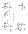
- Fig. 1 shows a three-phase squirrel-cage motor M and its starter, which, in each phase, comprises a diode D whose anode is connected to the supplying mains L1, L2 and L3 while its cathode is connected to the motor input terminal 1, 2 or 3, and a thyristor T connected in inverse-parallel with the diode, the cathode of the thyristor being connected to the supplying mains while its anode is connected to the motor input terminal.
- each thyristor consists of a first resistor R1, whose first terminal is connected via diode D1 to the motor input terminal for the phase in question, and a second resistor R2 of a resistance value equal to that of the first resistor, the first terminal of the second resistor being connected to the second terminal of the first resistor while its second terminal is connected to a point between the corresponding diode D1 and first resistor R1 in the control circuit of another phase.
- the firing circuit comprises a third resistor R3, which is adjustable and has its first terminal connected between the first and second resistors while its second terminal is connected via a DIAC P to the grid of the thyristor and also, via a capacitor C, to the mains phase.
- Fig. 2 shows a circuit which is used for starting the motor with a starter 4 constructed as illustrated in fig. 1, and which allows the motor to be supplied directly from the mains during normal operation.
- the motor is connected to the mains via a mains switch k1, which is controlled by means of a switch s connected in series with the relay K1 of the switch as illustrated by the diagram in fig. 3.
- a switch b controlled by the relay B of a unit monitoring the firing angle of the thyristor in the inverse-parallel circuit of the first phase, and the relay K L1 of a switch k L1 connected in parallel with the starter.
- the action of the circuit is as follows. When switch s is closed, the mains switch k1 is closed. The mains voltage is now applied to the inverse-parallel circuit, a current starts flowing through the glow discharge lamp H in the firing angle monitoring circuit, relay B is energized and switch b is opened. The motor is started. Through diode D, the positive half-cycle of the sinusoidal voltage is passed to the motor, whereas the negative half-cycle of the wave flows via the thyristor T, which is controlled by a firing circuit as shown in fig. 1.
- the firing circuit increases the thyristor firing angle until the thyristor conducts during the whole or nearly the whole time of the negative half-cycle and the current through the glow discharge lamp H in the firing angle monitoring circuit stops flowing, causing relay B to release and switch b to be closed. After this, the motor is fed directly from the mains.
- the rate of acceleration can be adjusted by simultaneously varying the setting of the third resistor in the firing circuit of each phase.
Landscapes
- Engineering & Computer Science (AREA)
- Power Engineering (AREA)
- Motor And Converter Starters (AREA)
- Control Of Ac Motors In General (AREA)
- Ultra Sonic Daignosis Equipment (AREA)
- Measuring Or Testing Involving Enzymes Or Micro-Organisms (AREA)
- Paper (AREA)
- Executing Machine-Instructions (AREA)
- Farming Of Fish And Shellfish (AREA)
- Control Of Electric Motors In General (AREA)
Applications Claiming Priority (2)
| Application Number | Priority Date | Filing Date | Title |
|---|---|---|---|
| FI883415A FI87025C (fi) | 1988-07-19 | 1988-07-19 | Anordning foer styrning av en trefasig vaexelstroemsmotor vid start, saerskilt en kortslutningsmotor |
| FI883415 | 1988-07-19 |
Publications (3)
| Publication Number | Publication Date |
|---|---|
| EP0351821A2 true EP0351821A2 (de) | 1990-01-24 |
| EP0351821A3 EP0351821A3 (en) | 1990-07-04 |
| EP0351821B1 EP0351821B1 (de) | 1994-06-08 |
Family
ID=8526842
Family Applications (1)
| Application Number | Title | Priority Date | Filing Date |
|---|---|---|---|
| EP89113246A Expired - Lifetime EP0351821B1 (de) | 1988-07-19 | 1989-07-19 | Vorrichtung zur Regelung eines Dreiphasen-Wechselstrommotors, insbesondere eines Kurzschlussläufermotors |
Country Status (5)
| Country | Link |
|---|---|
| US (1) | US4978903A (de) |
| EP (1) | EP0351821B1 (de) |
| AT (1) | ATE107097T1 (de) |
| DE (1) | DE68915879T2 (de) |
| FI (1) | FI87025C (de) |
Cited By (3)
| Publication number | Priority date | Publication date | Assignee | Title |
|---|---|---|---|---|
| WO1999052202A1 (es) * | 1998-04-07 | 1999-10-14 | Electronica Industrial A.G.R., S.L. | Nuevo dispositivo de control digital, aplicable en motores de corriente alterna |
| ES2154969A1 (es) * | 1994-12-20 | 2001-04-16 | Redondo Alberto Gonzalez | Dispositivo de control digital, aplicable en motores de corriente alterna. |
| WO2003056693A1 (en) * | 2001-12-14 | 2003-07-10 | Aarno Ahola | Control apparatus for the starting of a three-phase high-voltage alternating-current motor |
Families Citing this family (5)
| Publication number | Priority date | Publication date | Assignee | Title |
|---|---|---|---|---|
| KR100397565B1 (ko) | 2001-01-16 | 2003-09-13 | 엘지산전 주식회사 | 다기능 하이브리드 개폐기 |
| GB2399886A (en) * | 2003-03-26 | 2004-09-29 | Secr Defence | Identifying degenerative brain disease using EEG or EMG measurements |
| CN1327602C (zh) * | 2004-10-19 | 2007-07-18 | 湖北追日电气设备有限公司 | 一种高压电动机降压软起动装置 |
| CA2939850A1 (en) * | 2014-03-13 | 2015-09-17 | Canrig Drilling Technology Ltd. | Predictive landing failsafe |
| CN104967362B (zh) * | 2015-07-03 | 2018-08-21 | 宁波绿凯节能科技有限公司 | 一种用于电机降压启动的控制电路 |
Family Cites Families (19)
| Publication number | Priority date | Publication date | Assignee | Title |
|---|---|---|---|---|
| DK133030A (de) * | ||||
| US3332008A (en) * | 1963-08-28 | 1967-07-18 | Westinghouse Electric Corp | Phase angle controlled firing circuit for valves in multi-phase system |
| US3387196A (en) * | 1965-10-07 | 1968-06-04 | Gen Motors Corp | Speed control system for alternating current induction motors |
| DE1613936B2 (de) * | 1967-09-15 | 1971-12-30 | Gebr. Honsberg, 5630 Remscheid | Mehrphasiger wechselstromsteller |
| US3526817A (en) * | 1968-07-15 | 1970-09-01 | Protection Controls Inc | Magnetic amplifier bias for three-phase motor control |
| DE2009752C3 (de) * | 1969-03-07 | 1975-03-06 | Institutul Politehnic, Cluj (Rumaenien) | Schaltungsanordnung zur Steuerung der Drehzahl eines Drehstrom-Asynchronmotors |
| DE1964376A1 (de) * | 1969-12-23 | 1971-07-01 | Schubert & Salzer Maschinen | Vorrichtung zum Sanfteinschalten einer elektrischen Last |
| DE2718604A1 (de) * | 1977-04-27 | 1978-11-02 | Alfred Dipl Ing Krumpe | Steuerschaltung fuer mehrphasige thyristoranordnungen |
| DE2721287A1 (de) * | 1977-05-12 | 1978-11-23 | Alfred Dipl Ing Krumpe | Anlaufsteuergeraet fuer drehstromasynchronmotoren |
| SU788324A1 (ru) * | 1979-01-15 | 1980-12-15 | Предприятие П/Я Г-4418 | Электропривод переменного тока |
| DE3009445A1 (de) * | 1980-03-12 | 1981-09-17 | Pekazett Baumaschinen GmbH, 6660 Zweibrücken | Drehzahlregelung fuer asynchronmotoren |
| SU884064A1 (ru) * | 1980-03-18 | 1981-11-23 | Московский Завод "Динамо" Им.С.М.Кирова | Устройство дл регулировани частоты вращени короткозамкнутого асинхронного электродвигател |
| SU890540A1 (ru) * | 1980-03-26 | 1981-12-15 | Всесоюзный Научно-Исследовательский И Проектно-Технологический Институт Кранового И Тягового Электрооборудования | Устройство дл регулировани частоты вращени асинхронного электродвигател |
| DE3046406A1 (de) * | 1980-12-10 | 1982-07-22 | IWE Ingenieurgesellschaft für wirtschaftliche Energienutzung mbH, 6078 Neu-Isenburg | Verfahren und schaltungsanordnung zum regeln bzw. steuern der drehzahl eines mit drehstrom betriebenen motors |
| BE889496A (fr) * | 1981-07-03 | 1981-11-03 | Dumont Gilbert C | Inverseur statique polyphase |
| JPS5829391A (ja) * | 1981-08-12 | 1983-02-21 | Toshiba Corp | Dcモ−タドライブ回路 |
| US4482853A (en) * | 1981-08-24 | 1984-11-13 | Reuland Electric Company | Composite control for soft start and dynamic braking of a three-phase induction motor |
| US4469998A (en) * | 1982-12-16 | 1984-09-04 | The United States Of America As Represented By The Administrator Of The National Aeronautics And Space Administration | Three-phase power factor controller with induced emf sensing |
| FR2558656B1 (fr) * | 1984-01-23 | 1986-06-06 | Barrere Et Cie Sa Louis | Dispositif pour le demarrage d'un moteur electrique asynchrone |
-
1988
- 1988-07-19 FI FI883415A patent/FI87025C/fi active IP Right Grant
-
1989
- 1989-07-17 US US07/380,416 patent/US4978903A/en not_active Expired - Lifetime
- 1989-07-19 DE DE68915879T patent/DE68915879T2/de not_active Expired - Lifetime
- 1989-07-19 AT AT89113246T patent/ATE107097T1/de not_active IP Right Cessation
- 1989-07-19 EP EP89113246A patent/EP0351821B1/de not_active Expired - Lifetime
Cited By (3)
| Publication number | Priority date | Publication date | Assignee | Title |
|---|---|---|---|---|
| ES2154969A1 (es) * | 1994-12-20 | 2001-04-16 | Redondo Alberto Gonzalez | Dispositivo de control digital, aplicable en motores de corriente alterna. |
| WO1999052202A1 (es) * | 1998-04-07 | 1999-10-14 | Electronica Industrial A.G.R., S.L. | Nuevo dispositivo de control digital, aplicable en motores de corriente alterna |
| WO2003056693A1 (en) * | 2001-12-14 | 2003-07-10 | Aarno Ahola | Control apparatus for the starting of a three-phase high-voltage alternating-current motor |
Also Published As
| Publication number | Publication date |
|---|---|
| EP0351821B1 (de) | 1994-06-08 |
| DE68915879D1 (de) | 1994-07-14 |
| FI87025C (fi) | 1992-11-10 |
| ATE107097T1 (de) | 1994-06-15 |
| FI883415L (fi) | 1990-01-20 |
| FI883415A0 (fi) | 1988-07-19 |
| FI87025B (fi) | 1992-07-31 |
| US4978903A (en) | 1990-12-18 |
| EP0351821A3 (en) | 1990-07-04 |
| DE68915879T2 (de) | 1994-11-03 |
Similar Documents
| Publication | Publication Date | Title |
|---|---|---|
| RU2308821C2 (ru) | Усовершенствованный регулятор мощности | |
| GB1601880A (en) | Control circuit for periodically supplying current to a load circuit | |
| US3652924A (en) | Arrangement for controlling the current of an at least two-phase load with constant frequency supply voltage | |
| US4311951A (en) | Apparatus and method for high slip operation of an AC electric motor at substantially zero rotation and substantially zero torque | |
| EP0351821B1 (de) | Vorrichtung zur Regelung eines Dreiphasen-Wechselstrommotors, insbesondere eines Kurzschlussläufermotors | |
| US3742370A (en) | Soft start a c motor control | |
| US3657622A (en) | Control for adjusting and regulating the speed of an electric motor | |
| US3223911A (en) | Motor speed control system | |
| EP0315273A1 (de) | Schaltung zur Wechselstromregelung mittels einer Belastung | |
| US4134038A (en) | Speed control for a universal electric motor | |
| US4754211A (en) | Method of and a device for braking an asynchronous motor | |
| US4065673A (en) | Rotor controller systems for X-ray tubes | |
| US4145647A (en) | Arrangement for controlling the speed and rotary direction of a three-phase asynchronous motor | |
| JPH1127933A (ja) | 電気消費体の出力を制御する方法及び装置 | |
| US4160196A (en) | Two-phase ac electric motor control circuit | |
| RU2062546C1 (ru) | Устройство для управления трехфазным электродвигателем | |
| RU2842053C2 (ru) | Способ плавного пуска асинхронного двигателя с фазным ротором и устройство для его осуществления | |
| EP0203145A4 (de) | Mikroprozessor-geschwindigkeitsregler. | |
| WO2003056693A1 (en) | Control apparatus for the starting of a three-phase high-voltage alternating-current motor | |
| RU2035840C1 (ru) | Устройство для управления электроприводом | |
| SU1030944A1 (ru) | Электропривод грузоподъемного механизма с нереверсивным управлением | |
| SU748751A1 (ru) | Частотно-регулируемый электропривод | |
| SU1735833A1 (ru) | Устройство дл регулировани мощности | |
| RU1774453C (ru) | Способ пуска асинхронного электродвигател и устройство дл его осуществлени | |
| SU1115196A1 (ru) | Асинхронный вентильный каскад |
Legal Events
| Date | Code | Title | Description |
|---|---|---|---|
| PUAI | Public reference made under article 153(3) epc to a published international application that has entered the european phase |
Free format text: ORIGINAL CODE: 0009012 |
|
| AK | Designated contracting states |
Kind code of ref document: A2 Designated state(s): AT BE CH DE FR GB IT LI NL SE |
|
| PUAL | Search report despatched |
Free format text: ORIGINAL CODE: 0009013 |
|
| AK | Designated contracting states |
Kind code of ref document: A3 Designated state(s): AT BE CH DE FR GB IT LI NL SE |
|
| 17P | Request for examination filed |
Effective date: 19901205 |
|
| 17Q | First examination report despatched |
Effective date: 19921127 |
|
| GRAA | (expected) grant |
Free format text: ORIGINAL CODE: 0009210 |
|
| AK | Designated contracting states |
Kind code of ref document: B1 Designated state(s): AT BE CH DE FR GB IT LI NL SE |
|
| PG25 | Lapsed in a contracting state [announced via postgrant information from national office to epo] |
Ref country code: IT Free format text: LAPSE BECAUSE OF FAILURE TO SUBMIT A TRANSLATION OF THE DESCRIPTION OR TO PAY THE FEE WITHIN THE PRE;WARNING: LAPSES OF ITALIAN PATENTS WITH EFFECTIVE DATE BEFORE 2007 MAY HAVE OCCURRED AT ANY TIME BEFORE 2007. THE CORRECT EFFECTIVE DATE MAY BE DIFFERENT FROM THE ONE RECORDED.SCRIBED TIME-LIMIT Effective date: 19940608 Ref country code: NL Effective date: 19940608 Ref country code: BE Effective date: 19940608 Ref country code: LI Effective date: 19940608 Ref country code: FR Effective date: 19940608 Ref country code: CH Effective date: 19940608 Ref country code: AT Effective date: 19940608 |
|
| REF | Corresponds to: |
Ref document number: 107097 Country of ref document: AT Date of ref document: 19940615 Kind code of ref document: T |
|
| REF | Corresponds to: |
Ref document number: 68915879 Country of ref document: DE Date of ref document: 19940714 |
|
| REG | Reference to a national code |
Ref country code: CH Ref legal event code: PL |
|
| EN | Fr: translation not filed | ||
| NLV1 | Nl: lapsed or annulled due to failure to fulfill the requirements of art. 29p and 29m of the patents act | ||
| EAL | Se: european patent in force in sweden |
Ref document number: 89113246.6 |
|
| PLBE | No opposition filed within time limit |
Free format text: ORIGINAL CODE: 0009261 |
|
| STAA | Information on the status of an ep patent application or granted ep patent |
Free format text: STATUS: NO OPPOSITION FILED WITHIN TIME LIMIT |
|
| 26N | No opposition filed | ||
| REG | Reference to a national code |
Ref country code: GB Ref legal event code: IF02 |
|
| PGFP | Annual fee paid to national office [announced via postgrant information from national office to epo] |
Ref country code: DE Payment date: 20080722 Year of fee payment: 20 |
|
| PGFP | Annual fee paid to national office [announced via postgrant information from national office to epo] |
Ref country code: GB Payment date: 20080722 Year of fee payment: 20 |
|
| PGFP | Annual fee paid to national office [announced via postgrant information from national office to epo] |
Ref country code: SE Payment date: 20080714 Year of fee payment: 20 |
|
| REG | Reference to a national code |
Ref country code: GB Ref legal event code: PE20 Expiry date: 20090718 |
|
| EUG | Se: european patent has lapsed | ||
| PG25 | Lapsed in a contracting state [announced via postgrant information from national office to epo] |
Ref country code: GB Free format text: LAPSE BECAUSE OF EXPIRATION OF PROTECTION Effective date: 20090718 |