EP0351902B1 - Procédé de détermination de la porosité d'une formation souterraine en cours de forage - Google Patents
Procédé de détermination de la porosité d'une formation souterraine en cours de forage Download PDFInfo
- Publication number
- EP0351902B1 EP0351902B1 EP89201687A EP89201687A EP0351902B1 EP 0351902 B1 EP0351902 B1 EP 0351902B1 EP 89201687 A EP89201687 A EP 89201687A EP 89201687 A EP89201687 A EP 89201687A EP 0351902 B1 EP0351902 B1 EP 0351902B1
- Authority
- EP
- European Patent Office
- Prior art keywords
- bit
- porosity
- drill bit
- geometry
- tor
- Prior art date
- Legal status (The legal status is an assumption and is not a legal conclusion. Google has not performed a legal analysis and makes no representation as to the accuracy of the status listed.)
- Expired - Lifetime
Links
Images


Classifications
-
- E—FIXED CONSTRUCTIONS
- E21—EARTH OR ROCK DRILLING; MINING
- E21B—EARTH OR ROCK DRILLING; OBTAINING OIL, GAS, WATER, SOLUBLE OR MELTABLE MATERIALS OR A SLURRY OF MINERALS FROM WELLS
- E21B44/00—Automatic control systems specially adapted for drilling operations, i.e. self-operating systems which function to carry out or modify a drilling operation without intervention of a human operator, e.g. computer-controlled drilling systems; Systems specially adapted for monitoring a plurality of drilling variables or conditions
-
- E—FIXED CONSTRUCTIONS
- E21—EARTH OR ROCK DRILLING; MINING
- E21B—EARTH OR ROCK DRILLING; OBTAINING OIL, GAS, WATER, SOLUBLE OR MELTABLE MATERIALS OR A SLURRY OF MINERALS FROM WELLS
- E21B49/00—Testing the nature of borehole walls; Formation testing; Methods or apparatus for obtaining samples of soil or well fluids, specially adapted to earth drilling or wells
- E21B49/003—Testing the nature of borehole walls; Formation testing; Methods or apparatus for obtaining samples of soil or well fluids, specially adapted to earth drilling or wells by analysing drilling variables or conditions
Definitions
- the present invention relates to a method of determining the porosity of an underground formation being drilled. Knowing the porosity of the formations penetrated during the course of drilling an oil or gas well is useful both for the solution of a variety of drilling problems, such as determining the formation being drilled by correlation with offset wells and avoiding blow-outs by monitoring compaction trends, and for the estimation of the quantity of hydrocarbon recoverable from the well.
- the porosity of a formation can be estimated from measurements made with wireline density, neutron and sonic logging tools. These all have the major drawback that the measurements can only be made when the drill string has been pulled out of the borehole, so that they may not be made until several days after the formation was drilled. They cannot therefore be used to assist in the solution of current drilling problems.
- a number of mathematical models of the drilling process relate the rate of penetration of a drill bit to the weight on bit, the rotary speed of the bit, the bit geometry and wear state, and the drilling strength of the rock being drilled.
- SPE Society of Petroleum Engineer
- This invention provides a means of determining the porosity of a formation at the time that it is drilled by using measurements of the weight applied to the drill bit and the torque required to rotate the bit. These measurements are preferentially made downhole with equipment placed just above the drill bit in the drill string. They are commercially available with the Measurement While Drilling (MWD) technology.
- MWD Measurement While Drilling
- the parameters characteristic of the geometry of the drill bit, k1, k2 and a can be determined either by mathematical modelling or by experiments.
- the value of the parameter a can be determined by measuring the successive values of TOR and WOB when the bit is drilling through the same formation of substantially constant porosity.
- the values of parameters k1 and k2 can be determined by measuring the successive values of TOR and WOB for the same bit drilling formations of at least two known different porosities.
- bit wear is determined during the course of the drilling operation and the values of k1 and k2 are adjusted accordingly.
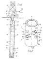
- an apparatus suitable for performing a method according to a preferred embodiment of the invention includes a measurement-while-drilling (MWD) tool 10 dependently coupled to the end of a drill string 11 comprised of one or more drill collars 12 and a plurality of tandemly connected joints 13 of drill pipe.
- Earth boring means such as a conventional drill bit 14, are positioned below the MWD tool.
- the drill string 11 is rotated by a rotary table 16 on a conventional drilling rig 15 at the surface. Mud is circulated through the drill string 11 and bit 14 in the direction of the arrows 17 and 18.
- the tool 10 further comprises a heavy walled tubular body which encloses weight and torque measuring means 20 adapted for measuring the torque (TOR) and weight (WOB) acting on the drill bit 14.
- Typical data signalling means 21 are adapted for transmitting encoded acoustic signals representative of the output of the sensors 20 to the surface through the downwardly flowing mud stream in the drill string 11. These acoustic signals are converted to electrical signals by a transducer 34 at the surface. The electrical signals are analyzed by appropriate data processing means 33 at the surface.
- the preferred embodiment comprises an MWD system to make the torque and weight-on-bit measurements downhole, in order to not take into account the frictions of the drill string along the wall of the borehole.
- the torque and weight-on-bit may be determined from surface measurement when these frictions are negligible.
- conventional sensors for measuring hookload and torque applied to the drill string, 36 and 37 respectively are located at the surface.
- a total depth sensor (not shown) is provided to allow for the correlation of measurements with depth.
- the external body 24 of the force-measuring means 20 is depicted somewhat schematically to illustrate the spatial relationships of the measurement axes of the body as the force-measuring means 20 measure weight and torque acting on the drill bit 14 during a typical drilling operation.
- the body 24 has a longitudinal or axial bore 25 of an appropriate diameter for carrying the stream of drilling mud flowing through the drill string 11.
- the body 24 is provided with a set of radial openings, B1, B2, B3 and B4, having their axes all lying in a transverse plane that intersects the longitudinal Z-axis 26 of the body. It will, of course, be recognized that in the depicted arrangement of the body 24 of the force-measuring means 20, these openings are cooperatively positioned so that they are respectively aligned with one another in the transverse plane that perpendicularly intersects with Z-axis 26 of the body.
- one pair of the holes B1 and B2 are respectively located on opposite sides of the body 24 and axially aligned with each other so that their respective central axes lie in the transverse plane and together define an X-axis 27 that is perpendicular to the Z-axis 26 of the body.
- the other two openings B2 and B4 are located in diametrically-opposite sides of the body 24 and are angularly offset by 90 degrees from the first set of openings B1 and B3 so that their aligned central axes respectively define the Y-axis 28 perpendicular to the Z-axis 26 as well as the X-axis 27.
- force-sensing means are mounted in each quadrant of the openings B1 and B3.
- these force-sensing means (such as typical strain gauges 41a-41d and 43a-43d) are respectively mounted as the 0-degrees, 90-degrees, 180-degrees and 270-degrees positions within the openings B1 and B3.
- rotational force-sensing means such as typical strain gauges (not illustrated) are mounted in each quadrant of the openings B2 and B4.
- a mathematical model has been developed to determine the relation between the drilling response of a particular bit and the lithology of the rock being drilled.
- TOR (k1 + k2.phi) WOBa (2) where k1, k2 and a are characteristic of the geometry of the drill bit in use. The values of these parameters depend on the size of the bit and of the type of bit (multicone bit or polycrystalline diamond carbide (PDC) bit for example).
- PDC polycrystalline diamond carbide
- a first alternative to determine the porosity of a formation being drilled in the field is to use cross plots representing torque versus weight-on-bit for different porosities, each cross plot being specific to a geometry of drill bit.
- Figure 3 represents a cross plot, torque versus weight-on-bit for different porosities phi1, phi2 and phi3, the value of the porosity increasing from phi1 to phi3.
- the cross plot can be made experimentally in the laboratory by drilling with a determined geometry of drill bit formations of different known porosities, and by measuring the successive values of torque with variations of weight-on-bit.
- the cross plots can also be derived from field data when formations of different known porosities are drilled and by measuring the torque values for different weights-on-bit.
- the porosity of a formation being drilled can be obtained easily from the cross plot corresponding to the geometry of drill bit in use by measuring at least one value of torque and weight-on-bit.
- the porosity is equal to phi2.
- Another alternative to determine the porosity is to compute first the values of the parameters k1, k2 and a, for the geometry of the drill bit in use.
- Parameter a is determined by measuring the successive values of torque and weight-on-bit when drilling a formation of constant known porosity. Then, by plotting, for example, the logarithm of torque versus the logarithm of weight-on-bit, the slope of the curve obtained is equal to a (this is clearly apparent from expression 2).
- the value of parameter a can vary between 0.5 to 2, but more likely between 1 and 1.5. In most cases, however, a good approximation of the value of the parameter a is 1.2 or 1.25.
- the same drill bit is used to drill rocks of different known porosities and the successive values of torque and weight-on-bit are measured.
- An easy way, for example, to obtain the value of parameter k2 is by drilling with the same weight-on-bit at least two rocks of different known porosities and to measure the corresponding two values of torque. The value of k2 is then easily obtained from equation (2), assuming the value of parameter a is known. Knowing k2, the value of k1 is directly derived from equation (2).
- Another alternative to determine the values of parameters k1, k2and a would be to model mathematically the interaction of the type of drill bit with formations of known porosities.
- the torque and weight-on-bit should be measured at suitable intervals during the drilling operation, say once every foot drilled, and the porosity of the formation drilled at that point can be computed using equation (3).
- the computed porosity can be plotted as a function of depth or another suitable indexing parameter to yield a log of porosity for the formations drilled.
- FIG. 4 An example of such a log is shown in Figure 4 in which the porosity phi (Fig 4a), expressed in %, is plotted as a function of the depth drilled (in meters).
- Fig 4a the porosity phi
- Fig 4a the porosity phi
- bit characterising parameters may change as the bit wears whilst drilling.
- the bit wear must be determined during the course of the drilling operation and the values of the bit characterising parameters adjusted accordingly.
- the wear state of the bit by the grading symbol T which ranges from 0 for an unworn bit to 8 for a bit on which the cutting structure is fully worn
- Figure 5 illustrates the influence of bit-tooth wear on bit torque for a milled tooth bit for two rocks of different porosities, phi1 (which was a marble) and phi2 (which was a sandstone), phi1 being lower than phi2.
- TOR/WOBa k10 + k11T + (k20 + k21T) phi (6)
- the curves representing TOR/WOBa as a function of T are straight lines, for constant values of phi.
Landscapes
- Geology (AREA)
- Life Sciences & Earth Sciences (AREA)
- Engineering & Computer Science (AREA)
- Mining & Mineral Resources (AREA)
- Environmental & Geological Engineering (AREA)
- Fluid Mechanics (AREA)
- Physics & Mathematics (AREA)
- General Life Sciences & Earth Sciences (AREA)
- Geochemistry & Mineralogy (AREA)
- Chemical & Material Sciences (AREA)
- Analytical Chemistry (AREA)
- Earth Drilling (AREA)
- Drilling And Boring (AREA)
Claims (8)
- Procédé pour déterminer la porosité d'une formation souterraine qui est en train d'être forée par un outil de forage rotatif (14) monté au niveau de l'extrémité inférieure d'une garniture de forage (11), qui comprend les étapes de mesure du couple (TOR) et du poids (WOB) appliqués sur l'outil (14) lorsqu'il fore la formation souterraine; de détermination de l'influence de la géométrie de l'outil de forage (14) sur la réponse du couple et du poids sur l'outil; et de détermination de la porosité (φ) de la formation qui est en train d'être forée à partir des valeurs mesurées de TOR et WOB; en tenant compte de l'influence de la géométrie de l'outil de forage (14), caractérisé en ce que la porosité (φ) est déterminée à partir de la relation

- Procédé selon la revendication 1, selon lequel la porosité φ de la formation qui est en train d'être forée sur le terrain au moyen dudit outil de forage (14) est déterminée par la mesure d'au moins une valeur de TOR et WOB et par l'utilisation de la représentation en coordonnées cartésiennes expérimentale correspondant à la géométrie dudit outil de forage (14) afin de déterminer la porosité de la formation qui est en train d'être forée.
- Procédé selon la revendication 1 ou 2, selon lequel ladite étape de détermination de l'influence de la géométrie de l'outil de forage (14) comprend la modélisation mathématique de l'outil de forage (14) de façon à créer un modèle qui décrit l'influence sur la réponse du couple et du poids sur l'outil pour différentes géométries d'outils de forage.
- Procédé selon la revendication 1, 2 ou 3, selon lequel la valeur du paramètre a est choisie entre 0,5 et 2, et de préférence entre 1 et 1,5.
- Procédé selon la revendication 4, selon lequel la valeur du paramètre a est choisie égale à environ 1,2.
- Procédé selon l'une des revendications précédentes, selon lequel la modification des états d'usure (T) de l'outil de forage (14) est surveillée pendant le forage, et l'influence de la géométrie de l'outil de forage (14) est corrigée afin de tenir compte de la modification de l'état d'usure de l'outil de forage (14).
- Procédé selon la revendication 6, selon lequel les valeurs des paramètres k₁ et k₂ sont calculées en fonction de l'état d'usure (T) de l'outil de forage (14), en mesurant les valeurs successives de TOR et WOB lors du forage de formations d'au moins deux valeurs connues de porosité (φ), en surveillant l'état d'usure T de l'outil de forage (14) pendant le forage, et en calculant les différentes valeurs de k₁ et k₂ en fonction de T par corrélation des valeurs de TOR, WOB, φ et T.
- Procédé selon la revendication 7, selon lequel


Applications Claiming Priority (2)
| Application Number | Priority Date | Filing Date | Title |
|---|---|---|---|
| GB8817215 | 1988-07-20 | ||
| GB8817215A GB2221043B (en) | 1988-07-20 | 1988-07-20 | Method of determining the porosity of an underground formation being drilled |
Publications (2)
| Publication Number | Publication Date |
|---|---|
| EP0351902A1 EP0351902A1 (fr) | 1990-01-24 |
| EP0351902B1 true EP0351902B1 (fr) | 1993-06-23 |
Family
ID=10640754
Family Applications (1)
| Application Number | Title | Priority Date | Filing Date |
|---|---|---|---|
| EP89201687A Expired - Lifetime EP0351902B1 (fr) | 1988-07-20 | 1989-06-27 | Procédé de détermination de la porosité d'une formation souterraine en cours de forage |
Country Status (6)
| Country | Link |
|---|---|
| US (1) | US4981036A (fr) |
| EP (1) | EP0351902B1 (fr) |
| CA (1) | CA1316525C (fr) |
| DE (1) | DE68907284T2 (fr) |
| GB (1) | GB2221043B (fr) |
| NO (1) | NO173524C (fr) |
Families Citing this family (15)
| Publication number | Priority date | Publication date | Assignee | Title |
|---|---|---|---|---|
| NO930044L (no) * | 1992-01-09 | 1993-07-12 | Baker Hughes Inc | Fremgangsmaate til vurdering av formasjoner og borkronetilstander |
| US5663073A (en) * | 1992-12-14 | 1997-09-02 | Atlantic Richfield Company | Earth formation porosity estimation method |
| US5368108A (en) * | 1993-10-26 | 1994-11-29 | Schlumberger Technology Corporation | Optimized drilling with positive displacement drilling motors |
| FR2729708A1 (fr) * | 1995-01-25 | 1996-07-26 | Inst Francais Du Petrole | Methode et systeme de diagraphie de parametres mecaniques des terrains traverses par un forage |
| US5668369A (en) * | 1995-12-18 | 1997-09-16 | Atlantic Richfield Company | Method and apparatus for lithology-independent well log analysis of formation water saturation |
| US6019180A (en) * | 1997-05-05 | 2000-02-01 | Schlumberger Technology Corporation | Method for evaluating the power output of a drilling motor under downhole conditions |
| DE20120461U1 (de) | 2001-12-18 | 2002-04-11 | Max Streicher GmbH & Co. KG aA, 94469 Deggendorf | Vorrichtung zur Messung innerer Kräfte und/oder Momente im Bohrgestänge von Erdbohrmaschinen |
| CN102900432B (zh) * | 2012-10-31 | 2016-01-20 | 中国石油集团川庆钻探工程有限公司 | 利用微钻时数据随钻计算录井孔隙度进行储层评价的方法 |
| EA033474B1 (ru) * | 2012-11-13 | 2019-10-31 | Exxonmobil Upstream Res Co | Способ обнаружения нарушений нормального хода бурения |
| FR3046809B1 (fr) * | 2016-01-20 | 2019-06-28 | Seti-Tec | Procede de determination de l'etat d'usage d'un foret, et dispositif correspondant |
| GB201801354D0 (en) * | 2018-01-26 | 2018-03-14 | Antech Ltd | Drilling apparatus and method for the determination of formation location |
| US10941644B2 (en) | 2018-02-20 | 2021-03-09 | Saudi Arabian Oil Company | Downhole well integrity reconstruction in the hydrocarbon industry |
| US20220268152A1 (en) * | 2021-02-22 | 2022-08-25 | Saudi Arabian Oil Company | Petro-physical property prediction |
| US11954800B2 (en) | 2021-12-14 | 2024-04-09 | Saudi Arabian Oil Company | Converting borehole images into three dimensional structures for numerical modeling and simulation applications |
| US11739616B1 (en) | 2022-06-02 | 2023-08-29 | Saudi Arabian Oil Company | Forming perforation tunnels in a subterranean formation |
Family Cites Families (13)
| Publication number | Priority date | Publication date | Assignee | Title |
|---|---|---|---|---|
| US2372576A (en) * | 1942-04-20 | 1945-03-27 | John T Hayward | Method of determining formation porosity during drilling |
| GB1439519A (en) * | 1973-11-02 | 1976-06-16 | Texaco Development Corp | Method and apapratus for rotary drilling |
| US4064749A (en) * | 1976-11-11 | 1977-12-27 | Texaco Inc. | Method and system for determining formation porosity |
| US4570480A (en) * | 1984-03-30 | 1986-02-18 | Nl Industries, Inc. | Method and apparatus for determining formation pressure |
| GB8411361D0 (en) * | 1984-05-03 | 1984-06-06 | Schlumberger Cambridge Researc | Assessment of drilling conditions |
| GB8418429D0 (en) * | 1984-07-19 | 1984-08-22 | Prad Res & Dev Nv | Estimating porosity |
| US4627276A (en) * | 1984-12-27 | 1986-12-09 | Schlumberger Technology Corporation | Method for measuring bit wear during drilling |
| CA1257405A (fr) * | 1985-12-10 | 1989-07-11 | John E. Fontenot | Methode et dispositif pour determiner le degre reel de la porosite d'un gisement par recours a des instruments de mesure aux neutrons au cours du forage |
| US4722095A (en) * | 1986-06-09 | 1988-01-26 | Mobil Oil Corporation | Method for identifying porosity and drilling mud invasion of a core sample from a subterranean formation |
| GB2205421A (en) * | 1987-06-03 | 1988-12-07 | Exploration Logging Inc | Computer-controlled model for determining internal friction angle, porosity, and fracture probability |
| US4876886A (en) * | 1988-04-04 | 1989-10-31 | Anadrill, Inc. | Method for detecting drilling events from measurement while drilling sensors |
| US4833914A (en) * | 1988-04-29 | 1989-05-30 | Anadrill, Inc. | Pore pressure formation evaluation while drilling |
| US4852399A (en) * | 1988-07-13 | 1989-08-01 | Anadrill, Inc. | Method for determining drilling conditions while drilling |
-
1988
- 1988-07-20 GB GB8817215A patent/GB2221043B/en not_active Expired - Lifetime
-
1989
- 1989-06-27 DE DE89201687T patent/DE68907284T2/de not_active Expired - Fee Related
- 1989-06-27 EP EP89201687A patent/EP0351902B1/fr not_active Expired - Lifetime
- 1989-06-28 US US07/372,987 patent/US4981036A/en not_active Expired - Lifetime
- 1989-07-12 CA CA000605509A patent/CA1316525C/fr not_active Expired - Fee Related
- 1989-07-14 NO NO892908A patent/NO173524C/no not_active IP Right Cessation
Also Published As
| Publication number | Publication date |
|---|---|
| CA1316525C (fr) | 1993-04-20 |
| GB8817215D0 (en) | 1988-08-24 |
| GB2221043B (en) | 1992-08-12 |
| DE68907284D1 (de) | 1993-07-29 |
| NO173524B (no) | 1993-09-13 |
| GB2221043A (en) | 1990-01-24 |
| DE68907284T2 (de) | 1994-01-13 |
| NO173524C (no) | 1993-12-22 |
| NO892908D0 (no) | 1989-07-14 |
| US4981036A (en) | 1991-01-01 |
| EP0351902A1 (fr) | 1990-01-24 |
| NO892908L (no) | 1990-01-22 |
Similar Documents
| Publication | Publication Date | Title |
|---|---|---|
| EP0350978B1 (fr) | Procédé pour la détermination de conditions de forage pendant le forage | |
| US4876886A (en) | Method for detecting drilling events from measurement while drilling sensors | |
| US4599904A (en) | Method for determining borehole stress from MWD parameter and caliper measurements | |
| US5358059A (en) | Apparatus and method for the dynamic measurement of a drill string employed in drilling | |
| EP0351902B1 (fr) | Procédé de détermination de la porosité d'une formation souterraine en cours de forage | |
| US4914591A (en) | Method of determining rock compressive strength | |
| US4662458A (en) | Method and apparatus for bottom hole measurement | |
| EP0263644B1 (fr) | Procédé pour rechercher les frottements et la perte de couple en cours de forage | |
| US4804051A (en) | Method of predicting and controlling the drilling trajectory in directional wells | |
| US5216917A (en) | Method of determining the drilling conditions associated with the drilling of a formation with a drag bit | |
| US5646611A (en) | System and method for indirectly determining inclination at the bit | |
| CA2093041C (fr) | Systeme et methode de surveillance de l'utilisation de l'outil de forage et de l'execution du plan du puits | |
| EP0339752B1 (fr) | Procédé d'évaluation de la pression de pores en cours du forage d'une formation | |
| CA2020960C (fr) | Methode de surveillance du forage de trous de sonde | |
| US4926686A (en) | Method for determining the wear of the cutting means of a tool during drilling a rocky formation | |
| Zannoni et al. | Development and field testing of a new downhole MWD drillstring dynamics sensor | |
| CN101116009A (zh) | 用于采用作为有侧限抗压强度的函数的钻头特定滑动摩擦系数和机械效率预测穿透率的方法 | |
| CA2598220A1 (fr) | Utilisation de mesures de fond de trou comme indicateurs de lithologie | |
| US5323648A (en) | Formation evaluation tool | |
| CA2336039C (fr) | Procede et appareil de determination rapide de la forme elliptique d'un trou de forage dans la terre | |
| CA2935247A1 (fr) | Modele permettant d'estimer l'usure d'un outil de forage | |
| GB2290330A (en) | Method of controlling the execution of a well drilling plan | |
| Tan et al. | Application and reliability analysis of DPM system in site investigation of HK weathered granite | |
| GB2043747A (en) | Drilling boreholes | |
| Peck | Performance monitoring of rotary blasthole drills |
Legal Events
| Date | Code | Title | Description |
|---|---|---|---|
| PUAI | Public reference made under article 153(3) epc to a published international application that has entered the european phase |
Free format text: ORIGINAL CODE: 0009012 |
|
| AK | Designated contracting states |
Kind code of ref document: A1 Designated state(s): DE FR IT NL |
|
| 17P | Request for examination filed |
Effective date: 19900625 |
|
| 17Q | First examination report despatched |
Effective date: 19910723 |
|
| GRAA | (expected) grant |
Free format text: ORIGINAL CODE: 0009210 |
|
| ITF | It: translation for a ep patent filed | ||
| AK | Designated contracting states |
Kind code of ref document: B1 Designated state(s): DE FR IT NL |
|
| REF | Corresponds to: |
Ref document number: 68907284 Country of ref document: DE Date of ref document: 19930729 |
|
| ET | Fr: translation filed | ||
| PLBE | No opposition filed within time limit |
Free format text: ORIGINAL CODE: 0009261 |
|
| STAA | Information on the status of an ep patent application or granted ep patent |
Free format text: STATUS: NO OPPOSITION FILED WITHIN TIME LIMIT |
|
| 26N | No opposition filed | ||
| PGFP | Annual fee paid to national office [announced via postgrant information from national office to epo] |
Ref country code: FR Payment date: 20030610 Year of fee payment: 15 |
|
| PGFP | Annual fee paid to national office [announced via postgrant information from national office to epo] |
Ref country code: NL Payment date: 20030630 Year of fee payment: 15 |
|
| PGFP | Annual fee paid to national office [announced via postgrant information from national office to epo] |
Ref country code: DE Payment date: 20030710 Year of fee payment: 15 |
|
| PG25 | Lapsed in a contracting state [announced via postgrant information from national office to epo] |
Ref country code: NL Free format text: LAPSE BECAUSE OF NON-PAYMENT OF DUE FEES Effective date: 20050101 Ref country code: DE Free format text: LAPSE BECAUSE OF NON-PAYMENT OF DUE FEES Effective date: 20050101 |
|
| PG25 | Lapsed in a contracting state [announced via postgrant information from national office to epo] |
Ref country code: FR Free format text: LAPSE BECAUSE OF NON-PAYMENT OF DUE FEES Effective date: 20050228 |
|
| NLV4 | Nl: lapsed or anulled due to non-payment of the annual fee |
Effective date: 20050101 |
|
| REG | Reference to a national code |
Ref country code: FR Ref legal event code: ST |
|
| PG25 | Lapsed in a contracting state [announced via postgrant information from national office to epo] |
Ref country code: IT Free format text: LAPSE BECAUSE OF NON-PAYMENT OF DUE FEES;WARNING: LAPSES OF ITALIAN PATENTS WITH EFFECTIVE DATE BEFORE 2007 MAY HAVE OCCURRED AT ANY TIME BEFORE 2007. THE CORRECT EFFECTIVE DATE MAY BE DIFFERENT FROM THE ONE RECORDED. Effective date: 20050627 |