EP0351990B1 - Hydrophone - Google Patents
Hydrophone Download PDFInfo
- Publication number
- EP0351990B1 EP0351990B1 EP89306914A EP89306914A EP0351990B1 EP 0351990 B1 EP0351990 B1 EP 0351990B1 EP 89306914 A EP89306914 A EP 89306914A EP 89306914 A EP89306914 A EP 89306914A EP 0351990 B1 EP0351990 B1 EP 0351990B1
- Authority
- EP
- European Patent Office
- Prior art keywords
- hydrophone
- former
- encapsulant
- coil
- encapsulant material
- Prior art date
- Legal status (The legal status is an assumption and is not a legal conclusion. Google has not performed a legal analysis and makes no representation as to the accuracy of the status listed.)
- Expired - Lifetime
Links
- 239000000463 material Substances 0.000 claims description 45
- 239000008393 encapsulating agent Substances 0.000 claims description 35
- 230000035945 sensitivity Effects 0.000 claims description 21
- 230000001133 acceleration Effects 0.000 claims description 15
- 230000000694 effects Effects 0.000 claims description 8
- 239000003822 epoxy resin Substances 0.000 claims description 6
- 229920000647 polyepoxide Polymers 0.000 claims description 6
- 239000013307 optical fiber Substances 0.000 claims description 4
- 239000007799 cork Substances 0.000 claims description 3
- 239000006260 foam Substances 0.000 claims description 3
- 239000000956 alloy Substances 0.000 claims description 2
- 229920001684 low density polyethylene Polymers 0.000 claims description 2
- 239000004702 low-density polyethylene Substances 0.000 claims description 2
- 239000004645 polyester resin Substances 0.000 claims description 2
- 229920001225 polyester resin Polymers 0.000 claims description 2
- 239000003570 air Substances 0.000 claims 3
- 239000000203 mixture Substances 0.000 claims 1
- 229920001169 thermoplastic Polymers 0.000 claims 1
- 239000004416 thermosoftening plastic Substances 0.000 claims 1
- 239000000835 fiber Substances 0.000 description 7
- 239000004593 Epoxy Substances 0.000 description 3
- 230000003068 static effect Effects 0.000 description 3
- 229920001875 Ebonite Polymers 0.000 description 2
- 238000003491 array Methods 0.000 description 2
- 230000001419 dependent effect Effects 0.000 description 2
- 238000000034 method Methods 0.000 description 2
- 229910045601 alloy Inorganic materials 0.000 description 1
- 239000002131 composite material Substances 0.000 description 1
- 230000008878 coupling Effects 0.000 description 1
- 238000010168 coupling process Methods 0.000 description 1
- 238000005859 coupling reaction Methods 0.000 description 1
- 230000000593 degrading effect Effects 0.000 description 1
- 238000010586 diagram Methods 0.000 description 1
- 238000005516 engineering process Methods 0.000 description 1
- 230000002706 hydrostatic effect Effects 0.000 description 1
- 229920000728 polyester Polymers 0.000 description 1
- 229920005989 resin Polymers 0.000 description 1
- 239000011347 resin Substances 0.000 description 1
- 229920001187 thermosetting polymer Polymers 0.000 description 1
- 230000026683 transduction Effects 0.000 description 1
- 238000010361 transduction Methods 0.000 description 1
- XLYOFNOQVPJJNP-UHFFFAOYSA-N water Substances O XLYOFNOQVPJJNP-UHFFFAOYSA-N 0.000 description 1
Images
Classifications
-
- G—PHYSICS
- G01—MEASURING; TESTING
- G01H—MEASUREMENT OF MECHANICAL VIBRATIONS OR ULTRASONIC, SONIC OR INFRASONIC WAVES
- G01H9/00—Measuring mechanical vibrations or ultrasonic, sonic or infrasonic waves by using radiation-sensitive means, e.g. optical means
- G01H9/004—Measuring mechanical vibrations or ultrasonic, sonic or infrasonic waves by using radiation-sensitive means, e.g. optical means using fibre optic sensors
Definitions
- the present invention relates to hydrophones and more particularly to inertially insensitive optical fibre hydrophones.
- the optical fibre version is subject to inertial or acceleration sensitivity, due to its own mass: that is, it cannot tell whether it is "seeing" an acceleration or a static force such as an acoustic pressure.
- This sensitivity depends upon the detailed design of the sensor as well as the intrinsic transduction mechanism, and can be reduced by a "balanced” design which nulls the effect of the acceleration, or by appropriate design and choice of materials which renders the design inherently inertially insensitive.
- the present invention is concerned with a particular approach to balancing a fibre hydrophone in the longitudinal and/or perpendicular directions, for use in towed arrays and other underwater applications.
- the invention will be described with particular reference to a towed array, but is also relevant to dunking sonars and sonabuoys.
- the hydrophones are mounted from the strain members, which can be two or more.
- the forcing function causing the unwanted acceleration outputs is applied via these strain members. It is assumed that the hydrophone will be fastened to these strain members, since these are the only structural elements in the array.
- GB-A-2 189 110 One way of obtaining balancing of a fibre coil, in the longitudinal direction is shown in GB-A-2 189 110.
- the hydrophone comprises a fibre coil having a mounting flange located midway along its length, such that axial/longitudinal acceleration causes equal and opposite distortions of the fibre on either side of the flange, thus cancelling the effects of axial acceleration.
- this does not compensate in the perpendicular direction, and might be difficult to realise as a device with a single fixing.
- Another example of standard practice in conventional piezo electric type hydrophones is where the piezo stack is attached at each end to plates which are attached to the source of the acceleration; the pressure sensitivity is unbalanced while longitudinal acceleration is balanced.
- An aim of the present invention is to provide some configurations in which some principles similar to those disclosed in GB-A-2 189 110 are used to achieve longitudinal and perpendicular balancing, while preserving acoustic sensitivity.
- a hydrophone comprising an optical fibre coil embedded in an encapsulant material, a rigid former having an axial part extending inside the coil in an axial direction with respect thereto, and means for attaching the former to strain members by which, in use, the hydrophone is carried, the encapsulant being mounted on the axial part of the former in such a way that inertial forces generated on opposite sides of the coil by the acceleration of the former in a direction perpendicular to the axial part cause opposite effects thereby reducing the inertial sensitivity of the hydrophone.
- the former comprises a central section orientated substantially orthogonal to and supporting said axial portion, wherein the coil comprises two portions positioned on said axial portion to either side of said central section, said central section driving the coil in a longitudinal direction providing longitudinal balancing such as to reduce inertial sensitivity.
- a secondary material having a lower bulk modulus than that of the encapsulant material is positioned between the former and the encapsulant material.
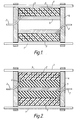
- FIG. 1 a structure for a typical underwater towed array application is shown.
- Longitudinal strain members 1 in the array are used to mount the internal equipment, including the hydrophones.
- a typical hydrophone might be as in the diagram, where the fibre coil 2 is encapsulated in a compressible material 3 and mounted on a rigid former attached to the strain members; the coil assembly is bonded well both to the ends of the bobbin shaped former and to the "axle" 5.
- Longitudinal balancing is achieved by the action of both the ends 4 and the axle 5, although some balancing could be achieved by either of these acting alone.
- the coil, driven symmetrically from within its circumference will always tend to be balanced, since a compressive force on one part will always be counteracted by opposite effects on another part of the coil.
- the axle part 5 of the rigid mount drives the coil in a perpendicular direction and consequently will achieve perpendicular balancing.
- the encapsulant material, and rigid material for the former By suitable choice of encapsulant material, and rigid material for the former, the acoustic sensitivity of the coil can be maintained.
- the encapsulant should be of low bulk modulus, while the former should be of light weight, and have stiffness.
- the rigid former could be made of a low mass alloy or a rigid thermoset material.
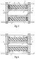
- a secondary material 6 is used between the coil 2 and the former 4, 5, of lower bulk modulus than the encapsulant 3.
- the material 6, an example of which is a low modulus epoxy resin, should have a higher compressibility than the encapsulant 3.
- the encapsulant 3 could be rubber or resin epoxy for example.
- Figure 4 illustrates an alternative realisation of the concept of Figure 3, in which the ends of the fibre encapsulant 3 are entirely unconstrained and the secondary material is air contained in gap 4c.
- the sensitivity to axial acceleration will now be dependent on the rigidity of the encapsulating material, and a material should be selected which yields a suitable compromise between maximum acoustic sensitivity and minimum acceleration sensitivity.
- the encapsulant 3 is supported on abutments 4a and sealed thereto by suitable means, for example o-rings 4b.
- the encapsulant 3 could be hard rubber, epoxy or polyester for example.
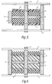
- Figure 5 is a design in which both perpendicular and longitudinal inertial insensitivity is achieved by driving from the centre, both axially and radially via central section 4.
- the acoustic sensitivity is maximised by appropriate choice of a compressible internal material 6 between the "axle" 5 and the encapsulant 3; this may result in the requirement for end caps 7 as shown.
- Two examples of end caps are shown which differ in that the ends of the encapsulant 3 may be either exposed or covered. These prevent static pressure acting via the compressible layer 6 on the inner surface of the encapsulant 3, which would counter the effect of the static pressure on the outer surface of the coil.
- Examples of high compressible materials are air and polyester resin.
- the encapsulant 3 could be hard rubber or a low density polyethylene for example. In the example of Figure 5, fewer layers of fibres 2 would be required to achieve the desired effect than would be the case if the compressible material was not present.
- Figure 6 represents a hydrophone in which the inertial sensitivity is reduced by ensuring the device is mechanically driven from the centre via central section 4.
- the end plates 7 act as piston, transferring pressure to the encapsulated fibre 2, whilst the secondary material 6 allows the encapsulant to expand in the perpendicular direction to an extent dependent upon its properties.
- the secondary material 6, should be a pressure release material i.e. it reflects sound waves in water, examples of which are, air, cork with rubber, and foam.
- the encapsulant material 3 could be soft rubber, or soft epoxy composite.
Landscapes
- Physics & Mathematics (AREA)
- General Physics & Mathematics (AREA)
- Transducers For Ultrasonic Waves (AREA)
- Measurement Of Mechanical Vibrations Or Ultrasonic Waves (AREA)
- Measurement Of Velocity Or Position Using Acoustic Or Ultrasonic Waves (AREA)
Claims (12)
- Hydrophone comprenant une bobine de fibre optique (2) noyée dans un matériau encapsulant compressible (3), un gabarit d'enroulement rigide ayant une partie axiale (5) qui s'étend à l'intérieur de la bobine (2) dans une direction axiale par rapport à celle-ci, et des dispositifs pour fixer le gabarit d'enroulement à des élément d'ancrage (1) par lesquels, en fonctionnement, l'hydrophone est porté, l'encapsulant (3) étant monté sur la partie axiale (5) du gabarit d'enroulement, de telle manière que les forces inertielles produites sur les côtés opposés de la bobine (2) par l'accélération du gabarit d'enroulement dans une direction perpendiculaire à la partie axiale provoquent des effets opposés en réduisant ainsi la sensiblité inertielle de l'hydrophone.
- Hydrophone selon la revendication 1, dans lequel le gabarit d'enroulement comprend en outre une section centrale (4) orientée sensiblement perpendiculairement à ladite partie axiale (5) qu'elle supporte, deux capuchons (7) sont placés sur ladite partie axiale de chaque côté de ladite section centrale (4), ladite section centrale (4) entraînant la bobine (2) dans une direction longitudinale en procurant un équilibrage longitudinal de la bobine (2) de manière à réduire la sensibilité inertielle.
- Hydrophone selon la revendication 1, dans lequel le gabarit d'enroulement rigide est en forme de bobine et comprend une partie axiale (5) et des parties terminales (4), les parties terminales entraînant la bobine (2) dans une direction longitudinale en procurant un équilibrage longitudinal de la bobine (2) de manière à réduire la sensibilité inertielle.
- Hydrophone selon la revendication 1, dans lequel le gabarit d'enroulement comprend des parties terminales (7) qui sont distantes de la partie axiale (5) et qui agissent comme des pistons transférant la pression au matériau encapsulant (3).
- Hydrophone selon la revendication 4, dans lequel un matériau secondaire (6) ayant un module d'élasticité spatiale inférieur à celui du matériau encapsulant (3) entoure les surfaces du matériau encapsulant (3) qui ne sont pas adjacentes aux parties terminales (7).
- Hydrophone selon l'une quelconque des revendications 1 à 3, dans lequel un matériau secondaire (6) ayant un module d'élasticité spatiale inférieur à celui du matériau encapsulant (3) est placé entre le gabarit d'enroulement et le matériau encapsulant (3).
- Hydrophone selon l'une quelconque des revendications précédentes, dans lequel le gabarit d'enroulement rigide présente des propriétés de faible masse et de rigidité.
- Hydrophone selon l'une quelconque des revendications précédentes, dans lequel le gabarit d'enroulement rigide est en un matériau d'alliage de faible masse.
- Hydrophone selon l'une quelconque des revendications précédentes, dans lequel le matériau encapsulant (3) est lié au gabarit d'enroulement rigide.
- Hydrophone selon la revendication 5 ou 6, dans lequel le matériau encapsulant (3) est du caoutchouc une résine époxy et le matériau secondaire (6) est une résine époxy de module d'élasticité spatiale inférieur à celui de l'encapsulant.
- Hydrophone selon la revendication 5 ou 6, dans lequel le matériau encapsulant (3) est du caoutchouc ou un polyéthylène basse densité et le matériau secondaire (6) est l'air, une mousse, du liège, une composition à base d'air, une matière thermoplastique, une résine époxy ou une résine de polyester.
- Hydrophone selon la revendication 5 ou 6, dans lequel le matériau encapsulant (3) est du caoutchouc mou ou une résine époxy molle et le matériau secondaire (6) et l'air, du liège avec du caoutchouc ou une mousse.
Applications Claiming Priority (2)
| Application Number | Priority Date | Filing Date | Title |
|---|---|---|---|
| GB8817256 | 1988-07-20 | ||
| GB8817256A GB2221120B (en) | 1988-07-20 | 1988-07-20 | A hydrophone |
Publications (3)
| Publication Number | Publication Date |
|---|---|
| EP0351990A2 EP0351990A2 (fr) | 1990-01-24 |
| EP0351990A3 EP0351990A3 (fr) | 1991-11-06 |
| EP0351990B1 true EP0351990B1 (fr) | 1994-04-06 |
Family
ID=10640775
Family Applications (1)
| Application Number | Title | Priority Date | Filing Date |
|---|---|---|---|
| EP89306914A Expired - Lifetime EP0351990B1 (fr) | 1988-07-20 | 1989-07-07 | Hydrophone |
Country Status (5)
| Country | Link |
|---|---|
| US (1) | US4998226A (fr) |
| EP (1) | EP0351990B1 (fr) |
| AU (1) | AU623664B2 (fr) |
| DE (1) | DE68914354T2 (fr) |
| GB (1) | GB2221120B (fr) |
Families Citing this family (15)
| Publication number | Priority date | Publication date | Assignee | Title |
|---|---|---|---|---|
| GB9026587D0 (en) * | 1990-12-06 | 1991-04-24 | Marconi Gec Ltd | Improvements relating to optical fibre coil assemblies |
| US5253222A (en) * | 1992-01-28 | 1993-10-12 | Litton Systems, Inc. | Omnidirectional fiber optic hydrophone |
| NO930279D0 (no) * | 1992-01-28 | 1993-01-27 | Litton Systems Inc | Rundtstraalende fiberoptisk hydrofon |
| GB2312503A (en) * | 1996-04-26 | 1997-10-29 | Marconi Gec Ltd | Two-part balancing coil assembly compensates for vibration |
| US5781510A (en) * | 1997-01-17 | 1998-07-14 | Input/Output, Inc. | Hydrophone housing for a solid marine seismic cable |
| US6188646B1 (en) | 1999-03-29 | 2001-02-13 | Syntron, Inc. | Hydrophone carrier |
| US6498769B1 (en) | 2000-08-04 | 2002-12-24 | Input/Output, Inc. | Method and apparatus for a non-oil-filled towed array with a novel hydrophone design and uniform buoyancy technique |
| CN101598594B (zh) * | 2009-06-17 | 2011-08-10 | 中国科学院半导体研究所 | 光纤水听器拖曳阵保护支架 |
| PT106487A (pt) * | 2012-08-03 | 2014-02-03 | Joao Manuel Machado Pinto Germano | Painéis de aglomerado de cortiça expandida com fibra óptica |
| CN110006518A (zh) * | 2019-03-26 | 2019-07-12 | 中国船舶重工集团公司第七一五研究所 | 振动抵消碟型光纤平面水听器 |
| CN110006517A (zh) * | 2019-03-26 | 2019-07-12 | 中国船舶重工集团公司第七一五研究所 | 空气背衬无弹性体光纤水听器探头及加工方法 |
| CN110006519A (zh) * | 2019-03-26 | 2019-07-12 | 中国船舶重工集团公司第七一五研究所 | 一体化增敏结构的空气背衬光纤水听器探头 |
| CN112781713A (zh) * | 2020-12-25 | 2021-05-11 | 海鹰企业集团有限责任公司 | 一种干涉型光纤水听器压力平衡结构 |
| JP7748881B2 (ja) * | 2021-01-19 | 2025-10-03 | 古河電気工業株式会社 | 音響検出センサ、音響検出装置 |
| AU2023382382A1 (en) * | 2022-11-14 | 2025-05-01 | Raytheon Company | Acoustic system with increased sensitivity |
Family Cites Families (8)
| Publication number | Priority date | Publication date | Assignee | Title |
|---|---|---|---|---|
| US2762032A (en) * | 1954-11-26 | 1956-09-04 | Shell Dev | Seismic hydrophone |
| US2837731A (en) * | 1955-04-19 | 1958-06-03 | Harris Transducer Corp | Hydrophone cable |
| FR1486401A (fr) * | 1965-05-22 | 1967-06-30 | Inst Francais Du Petrole | Capteurs de pression insensibles aux bruits parasites |
| US4193130A (en) * | 1978-09-07 | 1980-03-11 | The United States Of America As Represented By The Secretary Of The Navy | Fiber optic hydrophone for use as an underwater electroacoustic standard |
| US4471474A (en) * | 1979-09-28 | 1984-09-11 | Hughes Aircraft Company | Coupled waveguide acousto-optic hydrophone |
| US4405198A (en) * | 1981-08-25 | 1983-09-20 | The United States Of America As Represented By The Secretary Of The Navy | Extended fiber optic sensor using birefringent fibers |
| US4510588A (en) * | 1981-12-22 | 1985-04-09 | Shell Oil Company | Hydrophone cable decoupler |
| GB2189110B (en) * | 1986-03-17 | 1989-11-15 | Plessey Co Plc | Improvements relating to optical fibre hydrophones |
-
1988
- 1988-07-20 GB GB8817256A patent/GB2221120B/en not_active Expired - Lifetime
-
1989
- 1989-07-07 EP EP89306914A patent/EP0351990B1/fr not_active Expired - Lifetime
- 1989-07-07 DE DE68914354T patent/DE68914354T2/de not_active Expired - Fee Related
- 1989-07-11 AU AU38009/89A patent/AU623664B2/en not_active Ceased
- 1989-07-18 US US07/381,086 patent/US4998226A/en not_active Expired - Lifetime
Also Published As
| Publication number | Publication date |
|---|---|
| AU3800989A (en) | 1990-01-25 |
| GB2221120A (en) | 1990-01-24 |
| DE68914354T2 (de) | 1994-07-28 |
| AU623664B2 (en) | 1992-05-21 |
| US4998226A (en) | 1991-03-05 |
| DE68914354D1 (de) | 1994-05-11 |
| EP0351990A2 (fr) | 1990-01-24 |
| GB2221120B (en) | 1992-07-15 |
| GB8817256D0 (en) | 1988-11-16 |
| EP0351990A3 (fr) | 1991-11-06 |
Similar Documents
| Publication | Publication Date | Title |
|---|---|---|
| EP0351990B1 (fr) | Hydrophone | |
| US5600608A (en) | Hydrophone carrier | |
| US5646470A (en) | Acoustic transducer | |
| CA2552648C (fr) | Hydrophone souple | |
| US6108274A (en) | Acoustic sensor and array thereof | |
| US20020015359A1 (en) | Supporting structure of hydrophones for towed array sonar system | |
| EP1563323B1 (fr) | Capteur de vibration a tension en flexion | |
| US4326275A (en) | Directional transducer | |
| US6128251A (en) | Solid marine seismic cable | |
| US5287332A (en) | Acoustic particle acceleration sensor and array of such sensors | |
| US5982708A (en) | Acoustic sensor and array thereof | |
| US5774423A (en) | Acoustic sensor and array thereof | |
| US10448181B2 (en) | Method of manufacturing a low density underwater accelerometer | |
| US4827459A (en) | High sensitivity accelerometer for crossed dipoles acoustic sensors | |
| EP0098017A2 (fr) | Transducteur sonore utilisant des anches aboutissant à un alourdissement | |
| EP0456302A2 (fr) | Montage inter-éléments dans un transducteur piézoélectrique entassé | |
| EP1481225B1 (fr) | Ensemble detection optique | |
| KR102250987B1 (ko) | 압축형 가속도 센서 및 이의 조립 방법 | |
| US6002649A (en) | Tapered cylinder electro-acoustic transducer with reversed tapered driver | |
| KR102170736B1 (ko) | 선배열 예인센서에 적용 가능한 가속도 센서 | |
| RU2679931C1 (ru) | Комбинированный векторно-скалярный приемник | |
| US10197689B1 (en) | Physically damped noise canceling hydrophone | |
| US4797863A (en) | Underwater acoustical transducer | |
| AU680489B2 (en) | Hydrophone carrier | |
| US5784341A (en) | Underwater acoustic transmitter for large submersion |
Legal Events
| Date | Code | Title | Description |
|---|---|---|---|
| PUAI | Public reference made under article 153(3) epc to a published international application that has entered the european phase |
Free format text: ORIGINAL CODE: 0009012 |
|
| AK | Designated contracting states |
Kind code of ref document: A2 Designated state(s): DE FR IT SE |
|
| RAP1 | Party data changed (applicant data changed or rights of an application transferred) |
Owner name: GEC-MARCONI LIMITED |
|
| PUAL | Search report despatched |
Free format text: ORIGINAL CODE: 0009013 |
|
| AK | Designated contracting states |
Kind code of ref document: A3 Designated state(s): DE FR IT SE |
|
| 17P | Request for examination filed |
Effective date: 19911012 |
|
| 17Q | First examination report despatched |
Effective date: 19921211 |
|
| GRAA | (expected) grant |
Free format text: ORIGINAL CODE: 0009210 |
|
| AK | Designated contracting states |
Kind code of ref document: B1 Designated state(s): DE FR IT SE |
|
| ITF | It: translation for a ep patent filed | ||
| REF | Corresponds to: |
Ref document number: 68914354 Country of ref document: DE Date of ref document: 19940511 |
|
| ET | Fr: translation filed | ||
| EAL | Se: european patent in force in sweden |
Ref document number: 89306914.6 |
|
| PLBE | No opposition filed within time limit |
Free format text: ORIGINAL CODE: 0009261 |
|
| STAA | Information on the status of an ep patent application or granted ep patent |
Free format text: STATUS: NO OPPOSITION FILED WITHIN TIME LIMIT |
|
| 26N | No opposition filed | ||
| REG | Reference to a national code |
Ref country code: FR Ref legal event code: TP |
|
| PGFP | Annual fee paid to national office [announced via postgrant information from national office to epo] |
Ref country code: DE Payment date: 20070705 Year of fee payment: 19 |
|
| PGFP | Annual fee paid to national office [announced via postgrant information from national office to epo] |
Ref country code: IT Payment date: 20070731 Year of fee payment: 19 Ref country code: SE Payment date: 20070704 Year of fee payment: 19 |
|
| PGFP | Annual fee paid to national office [announced via postgrant information from national office to epo] |
Ref country code: FR Payment date: 20070710 Year of fee payment: 19 |
|
| EUG | Se: european patent has lapsed | ||
| PG25 | Lapsed in a contracting state [announced via postgrant information from national office to epo] |
Ref country code: DE Free format text: LAPSE BECAUSE OF NON-PAYMENT OF DUE FEES Effective date: 20090203 |
|
| REG | Reference to a national code |
Ref country code: FR Ref legal event code: ST Effective date: 20090331 |
|
| PG25 | Lapsed in a contracting state [announced via postgrant information from national office to epo] |
Ref country code: IT Free format text: LAPSE BECAUSE OF NON-PAYMENT OF DUE FEES Effective date: 20080707 Ref country code: FR Free format text: LAPSE BECAUSE OF NON-PAYMENT OF DUE FEES Effective date: 20080731 |
|
| PG25 | Lapsed in a contracting state [announced via postgrant information from national office to epo] |
Ref country code: SE Free format text: LAPSE BECAUSE OF NON-PAYMENT OF DUE FEES Effective date: 20080708 |