EP0351999B1 - Transmission pour transmettre un mouvement de rotation d'un arbre à un autre - Google Patents
Transmission pour transmettre un mouvement de rotation d'un arbre à un autre Download PDFInfo
- Publication number
- EP0351999B1 EP0351999B1 EP89306993A EP89306993A EP0351999B1 EP 0351999 B1 EP0351999 B1 EP 0351999B1 EP 89306993 A EP89306993 A EP 89306993A EP 89306993 A EP89306993 A EP 89306993A EP 0351999 B1 EP0351999 B1 EP 0351999B1
- Authority
- EP
- European Patent Office
- Prior art keywords
- link
- shaft
- mechanism according
- retaining plate
- mounting
- Prior art date
- Legal status (The legal status is an assumption and is not a legal conclusion. Google has not performed a legal analysis and makes no representation as to the accuracy of the status listed.)
- Expired - Lifetime
Links
- 230000007246 mechanism Effects 0.000 title claims description 25
- 230000015572 biosynthetic process Effects 0.000 description 1
- 238000002485 combustion reaction Methods 0.000 description 1
- 238000010276 construction Methods 0.000 description 1
- 230000000694 effects Effects 0.000 description 1
- 238000000034 method Methods 0.000 description 1
- 230000004048 modification Effects 0.000 description 1
- 238000012986 modification Methods 0.000 description 1
- 230000000717 retained effect Effects 0.000 description 1
- 238000010008 shearing Methods 0.000 description 1
Images

Classifications
-
- F—MECHANICAL ENGINEERING; LIGHTING; HEATING; WEAPONS; BLASTING
- F16—ENGINEERING ELEMENTS AND UNITS; GENERAL MEASURES FOR PRODUCING AND MAINTAINING EFFECTIVE FUNCTIONING OF MACHINES OR INSTALLATIONS; THERMAL INSULATION IN GENERAL
- F16H—GEARING
- F16H21/00—Gearings comprising primarily only links or levers, with or without slides
- F16H21/10—Gearings comprising primarily only links or levers, with or without slides all movement being in, or parallel to, a single plane
- F16H21/12—Gearings comprising primarily only links or levers, with or without slides all movement being in, or parallel to, a single plane for conveying rotary motion
- F16H21/14—Gearings comprising primarily only links or levers, with or without slides all movement being in, or parallel to, a single plane for conveying rotary motion by means of cranks, eccentrics, or like members fixed to one rotary member and guided along tracks on the other
-
- F—MECHANICAL ENGINEERING; LIGHTING; HEATING; WEAPONS; BLASTING
- F16—ENGINEERING ELEMENTS AND UNITS; GENERAL MEASURES FOR PRODUCING AND MAINTAINING EFFECTIVE FUNCTIONING OF MACHINES OR INSTALLATIONS; THERMAL INSULATION IN GENERAL
- F16H—GEARING
- F16H1/00—Toothed gearings for conveying rotary motion
- F16H1/28—Toothed gearings for conveying rotary motion with gears having orbital motion
- F16H1/32—Toothed gearings for conveying rotary motion with gears having orbital motion in which the central axis of the gearing lies inside the periphery of an orbital gear
-
- F—MECHANICAL ENGINEERING; LIGHTING; HEATING; WEAPONS; BLASTING
- F16—ENGINEERING ELEMENTS AND UNITS; GENERAL MEASURES FOR PRODUCING AND MAINTAINING EFFECTIVE FUNCTIONING OF MACHINES OR INSTALLATIONS; THERMAL INSULATION IN GENERAL
- F16H—GEARING
- F16H35/00—Gearings or mechanisms with other special functional features
- F16H35/10—Arrangements or devices for absorbing overload or preventing damage by overload
-
- Y—GENERAL TAGGING OF NEW TECHNOLOGICAL DEVELOPMENTS; GENERAL TAGGING OF CROSS-SECTIONAL TECHNOLOGIES SPANNING OVER SEVERAL SECTIONS OF THE IPC; TECHNICAL SUBJECTS COVERED BY FORMER USPC CROSS-REFERENCE ART COLLECTIONS [XRACs] AND DIGESTS
- Y10—TECHNICAL SUBJECTS COVERED BY FORMER USPC
- Y10T—TECHNICAL SUBJECTS COVERED BY FORMER US CLASSIFICATION
- Y10T74/00—Machine element or mechanism
- Y10T74/18—Mechanical movements
- Y10T74/1836—Rotary to rotary
-
- Y—GENERAL TAGGING OF NEW TECHNOLOGICAL DEVELOPMENTS; GENERAL TAGGING OF CROSS-SECTIONAL TECHNOLOGIES SPANNING OVER SEVERAL SECTIONS OF THE IPC; TECHNICAL SUBJECTS COVERED BY FORMER USPC CROSS-REFERENCE ART COLLECTIONS [XRACs] AND DIGESTS
- Y10—TECHNICAL SUBJECTS COVERED BY FORMER USPC
- Y10T—TECHNICAL SUBJECTS COVERED BY FORMER US CLASSIFICATION
- Y10T74/00—Machine element or mechanism
- Y10T74/21—Elements
- Y10T74/2101—Cams
Definitions
- This invention relates to a mechanism for transmitting rotational motion from one shaft to another.
- a mechanism for transmitting rotational motion from one shaft to another shaft which is parallel to the first comprises a link which is constrained to perform an orbital motion, the shafts being connected to the link by cranks or by internal/external gear sets.
- a mechanism for transmitting rotational motion comprises a link which is constrained to move in an orbital path, an input shaft being connected to the link so that rotation of the input shaft will cause the link to move in its orbital path laterally to said input shaft and a second shaft parallel to said input shaft, said second shaft being connected to the link so that orbital motion of the link will cause the second shaft to rotate; characterised in that at least one of said shafts is connected to the link by a mounting which is capable of lateral movement in the plane of the link, said mounting making frictional engagement with the link so that when a lateral stress above a predetermined value is applied between the shaft and link, the mounting will move laterally to relieve the stress, said predetermined value being above the lateral stresses experienced during normal operation of the mechanism.
- one or both shafts are connected to the link by means of a crank.
- the crank on the end of the shaft engages in a bush which is located in an oversized aperture in the link.
- An external flange formation on one end of the bush bears against one face of the link while a Belleville washer is compressed between the other end of the bush and the other face of the link to apply a predetermined frictional load therebetween.
- one or both shafts may be connected to the link by means of gear sets, an external gear on the shaft engaging an internal gear on the link.
- the internal gear may be mounted in an oversized aperture in the link and frictionally secured thereto in a manner similar to that described above.
- the gear may be located in a retaining plate, the gear being located in an oversized aperture in the link and the retaining plate being secured to the link by fastening means which extend through oversized holes in the retaining plate or link and apply a predetermined frictional load therebetween, so that the retaining plate and gear is capable of moving relative to the link when the lateral load between the shaft and link exceeds the predetermined frictional load.
- the apertures in the link or retaining plate may be oversized in that direction only.
- the retaining plate may be pivotted about one point, so that movement of the retaining plate about the pivot will provide relief in the required direction.
- the retaining plate may be pivotted in an elongate hole so that pivotting of the retaining plate will give relief in one direction while the retaining plate is able to move linearly relative to the pivot to give relief in the other direction.
- the present invention will provide a self centering effect, for example if on initial assembly there is sufficient mislaignment to generate transverse loads in excess of the predetermined value, one or more of the mountings will shift to relieve the stress after which the mechanism will continue to transmit drive normally.
- the link may be constrained to perform orbital motion on one or more idler cranks, in which case, the idler cranks may also be connected to a link in the manner described above.
- Figure 1 illustrates a mechanism for connecting the crankshaft 10 of an internal combustion engine to twin overhead cam shafts 11 and 12.
- crankshaft 10 is connected to a link 13 by means of crank 14 which engages in bearing 15 in the link 13.
- the cam shafts 11 and 12 are connected to the link 13 by means of external gears 16 which engage internal gears 17 mounted on the link 13.
- the gear sets 16, 17 give a two to one drive ratio so that the cam shafts 11 and 12 will be rotated at half the speed of the crankshaft 10.
- An idler crank 20 is secured to the link 13 in order to stabilise the link 13 so that it will be driven by the crankshaft 10 in an orbital fashion.
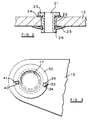
- the idler crank 20 is mounted to the link 13 in a bush 21 which is located in an oversized aperture 22 in the link 13.
- a flange portion 23 at one end of the bush 21 reacts against one face of the link 13 through a plane washer 24.
- a Belleville washer 25 is mounted on the other end 26 of bush 21 and engages the other face of the link 13, the end 26 of bush 21 being rinsed over so that a predetermined load is applied by the Belleville washer.
- the bush 21 may have an external screw thread so that the Belleville washer 25 may be retained thereon and adjusted to the appropriate load, by means of a nut.
- the internal gears 17 are mounted in retaining plates 30 and are located in oversized apertures 31 in the link 13, the retaining plates 30 abutting one face of the link 13.
- the retaining plates 30 are secured to the link 13 by means of three angularly spaced rivets or screw fastening means 32.
- the rivets or screw fastening means 32 are located through oversized holes 34 in the link 13 and Belleville washer 35 are arranged to act against the other face of the link 13, in similar manner to the arrangement illustrated in Figure 2.
- the bush 21 and internal gears 17 are thus mounted on the link 13 in a manner which, if subjected to lateral loads in excess of the predetermined frictional load, will permit movement thereof to relieve the lateral loads and thus avoid damage to the mechanism.
- the retaining plate 30 is secured to the link 13 by means of a pivot pin 40 which engages in an elongate hole 41 and by one rivet 32/Belleville washer 35 assembly as described above.
- a pivot pin 40 which engages in an elongate hole 41 and by one rivet 32/Belleville washer 35 assembly as described above.
- the mechanism in accordance with the present invention may be used to transmit rotation between two or more shafts.
- additional idler cranks instead of using additional idler cranks to constrain the link to move in an orbital path, other means, for example an Oldham linkage, may be used for this purpose.
Landscapes
- Engineering & Computer Science (AREA)
- General Engineering & Computer Science (AREA)
- Mechanical Engineering (AREA)
- Transmission Devices (AREA)
Claims (13)
Applications Claiming Priority (2)
| Application Number | Priority Date | Filing Date | Title |
|---|---|---|---|
| GB888817218A GB8817218D0 (en) | 1988-07-20 | 1988-07-20 | Mechanism for transmitting rotational motion from one shaft to another |
| GB8817218 | 1988-07-20 |
Publications (2)
| Publication Number | Publication Date |
|---|---|
| EP0351999A1 EP0351999A1 (fr) | 1990-01-24 |
| EP0351999B1 true EP0351999B1 (fr) | 1992-01-29 |
Family
ID=10640756
Family Applications (1)
| Application Number | Title | Priority Date | Filing Date |
|---|---|---|---|
| EP89306993A Expired - Lifetime EP0351999B1 (fr) | 1988-07-20 | 1989-07-10 | Transmission pour transmettre un mouvement de rotation d'un arbre à un autre |
Country Status (5)
| Country | Link |
|---|---|
| US (1) | US4958531A (fr) |
| EP (1) | EP0351999B1 (fr) |
| JP (1) | JPH0272257A (fr) |
| DE (1) | DE68900791D1 (fr) |
| GB (1) | GB8817218D0 (fr) |
Families Citing this family (3)
| Publication number | Priority date | Publication date | Assignee | Title |
|---|---|---|---|---|
| DE4320126C2 (de) * | 1992-06-17 | 2000-07-06 | Unisia Jecs Corp | Nockenwellenanordnung zur Verwendung in einem Verbrennungsmotor |
| EP2227644A1 (fr) * | 2007-10-26 | 2010-09-15 | Vishvas Ambardekar | Boite de vitesses excentrique modifiee |
| HUP1400594A2 (en) * | 2014-12-16 | 2016-07-28 | Atakomb Kft | Gearbox |
Family Cites Families (8)
| Publication number | Priority date | Publication date | Assignee | Title |
|---|---|---|---|---|
| US1326863A (en) * | 1919-12-30 | Spindle-head | ||
| US1378191A (en) * | 1920-05-12 | 1921-05-17 | Pale Paul | Mechanical movement |
| FR534186A (fr) * | 1921-04-16 | 1922-03-21 | Commande cinématique de distribution | |
| US2522735A (en) * | 1945-12-29 | 1950-09-19 | Zagar Tool Inc | Multiple spindle driving mechanism |
| JPS5229376B2 (fr) * | 1972-04-13 | 1977-08-02 | ||
| AU500374B2 (en) * | 1975-04-09 | 1979-05-17 | G. M Cupit | Improved sealing washer & method of producing same |
| SE421341B (sv) * | 1978-08-01 | 1981-12-14 | Petr Ilich Gorkov | Drivanordning for overforing av roterande rorelse fran en drivaxel till ett antal drivna axlar |
| GB2160612B (en) * | 1984-06-21 | 1987-12-02 | Jaguar Cars | A mechanism for transmitting rotational motion from one shaft to another |
-
1988
- 1988-07-20 GB GB888817218A patent/GB8817218D0/en active Pending
-
1989
- 1989-07-10 EP EP89306993A patent/EP0351999B1/fr not_active Expired - Lifetime
- 1989-07-10 DE DE8989306993T patent/DE68900791D1/de not_active Expired - Lifetime
- 1989-07-14 US US07/379,908 patent/US4958531A/en not_active Expired - Fee Related
- 1989-07-20 JP JP1188675A patent/JPH0272257A/ja active Pending
Also Published As
| Publication number | Publication date |
|---|---|
| EP0351999A1 (fr) | 1990-01-24 |
| US4958531A (en) | 1990-09-25 |
| JPH0272257A (ja) | 1990-03-12 |
| GB8817218D0 (en) | 1988-08-24 |
| DE68900791D1 (de) | 1992-03-12 |
Similar Documents
| Publication | Publication Date | Title |
|---|---|---|
| US6454656B2 (en) | Yoke connections for universal joints | |
| US6959682B2 (en) | Engine balancer with chain drive vibration isolation | |
| US4671223A (en) | Side mounted V-type 4-cycle engine | |
| US6454207B1 (en) | Flap support mechanism and a flap-equipped rotor blade | |
| US4050266A (en) | Drive coupling | |
| EP0351999B1 (fr) | Transmission pour transmettre un mouvement de rotation d'un arbre à un autre | |
| US4917573A (en) | Cooling fan isolation mount | |
| US20020106260A1 (en) | Screw connection with countersunk screw | |
| EP1151213B1 (fr) | Roue d'engrenage | |
| US4447217A (en) | Coupling with overload protection | |
| WO2002075170A1 (fr) | Joint a vis | |
| KR930006596B1 (ko) | 무한궤도차량용 구동시스템 | |
| JP5222440B2 (ja) | 動力伝達装置 | |
| EP0155785B1 (fr) | Disque mené pour embrayage à friction | |
| US5116283A (en) | Power transmission mechanism with two sets of chains | |
| US5148719A (en) | Torsional-vibration damper | |
| US4149607A (en) | Support link adjustment means | |
| RU2124648C1 (ru) | Механизм поворота лопаток направляющего аппарата гидротурбины | |
| EP0947670A2 (fr) | Entraínement d'arbre à cames d'un moteur à combustion interne | |
| JPH08284677A (ja) | ギヤトレーンの構造及びその組付方法 | |
| JPS599058Y2 (ja) | カ−ク−ラ−用コンプレツサ−の取付構造 | |
| JPH0540329Y2 (fr) | ||
| DE2709493A1 (de) | Elastische kupplung | |
| KR200155937Y1 (ko) | 오버헤드캠 엔진의 기어 백래시 자동 조정 장치 | |
| GB2244526A (en) | Compressor blade mounting arrangement |
Legal Events
| Date | Code | Title | Description |
|---|---|---|---|
| PUAI | Public reference made under article 153(3) epc to a published international application that has entered the european phase |
Free format text: ORIGINAL CODE: 0009012 |
|
| AK | Designated contracting states |
Kind code of ref document: A1 Designated state(s): DE FR GB IT SE |
|
| 17P | Request for examination filed |
Effective date: 19900301 |
|
| 17Q | First examination report despatched |
Effective date: 19910604 |
|
| GRAA | (expected) grant |
Free format text: ORIGINAL CODE: 0009210 |
|
| AK | Designated contracting states |
Kind code of ref document: B1 Designated state(s): DE FR GB IT SE |
|
| REF | Corresponds to: |
Ref document number: 68900791 Country of ref document: DE Date of ref document: 19920312 |
|
| ITF | It: translation for a ep patent filed | ||
| ET | Fr: translation filed | ||
| PG25 | Lapsed in a contracting state [announced via postgrant information from national office to epo] |
Ref country code: SE Effective date: 19920711 |
|
| PLBE | No opposition filed within time limit |
Free format text: ORIGINAL CODE: 0009261 |
|
| STAA | Information on the status of an ep patent application or granted ep patent |
Free format text: STATUS: NO OPPOSITION FILED WITHIN TIME LIMIT |
|
| 26N | No opposition filed | ||
| PG25 | Lapsed in a contracting state [announced via postgrant information from national office to epo] |
Ref country code: FR Effective date: 19930331 |
|
| PG25 | Lapsed in a contracting state [announced via postgrant information from national office to epo] |
Ref country code: DE Effective date: 19930401 |
|
| REG | Reference to a national code |
Ref country code: FR Ref legal event code: ST |
|
| PG25 | Lapsed in a contracting state [announced via postgrant information from national office to epo] |
Ref country code: GB Effective date: 19930710 |
|
| GBPC | Gb: european patent ceased through non-payment of renewal fee |
Effective date: 19930710 |
|
| EUG | Se: european patent has lapsed |
Ref document number: 89306993.0 Effective date: 19930204 |
|
| PG25 | Lapsed in a contracting state [announced via postgrant information from national office to epo] |
Ref country code: IT Free format text: LAPSE BECAUSE OF NON-PAYMENT OF DUE FEES;WARNING: LAPSES OF ITALIAN PATENTS WITH EFFECTIVE DATE BEFORE 2007 MAY HAVE OCCURRED AT ANY TIME BEFORE 2007. THE CORRECT EFFECTIVE DATE MAY BE DIFFERENT FROM THE ONE RECORDED. Effective date: 20050710 |