EP0352159B1 - Frequenzabweichungstolerierendes Verfahren und Vorrichtung zur Demodulation von, durch eine Binärsymbolreihe, winkelmodulierten Signalen mit konstanter Umhüllung und kontinuierlicher Phase - Google Patents
Frequenzabweichungstolerierendes Verfahren und Vorrichtung zur Demodulation von, durch eine Binärsymbolreihe, winkelmodulierten Signalen mit konstanter Umhüllung und kontinuierlicher Phase Download PDFInfo
- Publication number
- EP0352159B1 EP0352159B1 EP89401886A EP89401886A EP0352159B1 EP 0352159 B1 EP0352159 B1 EP 0352159B1 EP 89401886 A EP89401886 A EP 89401886A EP 89401886 A EP89401886 A EP 89401886A EP 0352159 B1 EP0352159 B1 EP 0352159B1
- Authority
- EP
- European Patent Office
- Prior art keywords
- phase
- bits
- differential phases
- phases
- differential
- Prior art date
- Legal status (The legal status is an assumption and is not a legal conclusion. Google has not performed a legal analysis and makes no representation as to the accuracy of the status listed.)
- Expired - Lifetime
Links
- 238000000034 method Methods 0.000 title claims description 33
- 238000005070 sampling Methods 0.000 claims description 37
- 210000001520 comb Anatomy 0.000 claims description 13
- 238000012545 processing Methods 0.000 claims description 13
- 230000006870 function Effects 0.000 claims description 9
- 230000015654 memory Effects 0.000 claims description 8
- 230000000694 effects Effects 0.000 claims description 3
- 238000012360 testing method Methods 0.000 claims description 2
- 238000012935 Averaging Methods 0.000 claims 1
- 238000010586 diagram Methods 0.000 description 7
- 230000005540 biological transmission Effects 0.000 description 4
- 238000011156 evaluation Methods 0.000 description 4
- 238000001914 filtration Methods 0.000 description 3
- 230000000717 retained effect Effects 0.000 description 3
- 230000015572 biosynthetic process Effects 0.000 description 2
- 230000001427 coherent effect Effects 0.000 description 2
- 238000012937 correction Methods 0.000 description 2
- 125000004122 cyclic group Chemical group 0.000 description 2
- 238000011282 treatment Methods 0.000 description 2
- 238000000429 assembly Methods 0.000 description 1
- 230000015556 catabolic process Effects 0.000 description 1
- 230000001364 causal effect Effects 0.000 description 1
- 238000006731 degradation reaction Methods 0.000 description 1
- 230000036039 immunity Effects 0.000 description 1
- 238000005259 measurement Methods 0.000 description 1
- 230000003071 parasitic effect Effects 0.000 description 1
- 230000004044 response Effects 0.000 description 1
- 230000035945 sensitivity Effects 0.000 description 1
- 230000003595 spectral effect Effects 0.000 description 1
- 238000012546 transfer Methods 0.000 description 1
- 230000017105 transposition Effects 0.000 description 1
Images


Classifications
-
- H—ELECTRICITY
- H04—ELECTRIC COMMUNICATION TECHNIQUE
- H04L—TRANSMISSION OF DIGITAL INFORMATION, e.g. TELEGRAPHIC COMMUNICATION
- H04L27/00—Modulated-carrier systems
- H04L27/10—Frequency-modulated carrier systems, i.e. using frequency-shift keying
- H04L27/14—Demodulator circuits; Receiver circuits
Definitions
- the invention relates to the demodulation of binary information signals transmitted by angular modulation of a carrier, and more particularly relates to a method, and the corresponding device, for demodulation of signals with constant envelope and continuous phase angularly modulated by a train of binary symbols, in English "CPM” modulation for "continuous phase modulation", tolerating large frequency drifts.
- Constant envelope modulations are widely used today in radiocommunications because of their immunity to nonlinear amplitude distortions.
- Frequency modulation with continuous phase in which the phase variation due to a binary element can be spread over several bit periods has interesting properties with regard to the rather reduced spectral congestion.
- the demodulation is carried out either in a coherent demodulator, with a phase reference, by discriminator, or in a non-coherent demodulator which can be of differential type.
- each stage allows the transmission of a certain number of bits, ie n b .
- the modulation applied is an angular modulation with continuous phase, the imperfection of the transmission channel, the very significant "Doppler” frequency drifts when the demodulator is on board (for example on an airplane), the instability of the oscillators of the reception chain, etc. ... disturb the signal. These different degradations result in frequency drifts.
- the method according to the invention consists in performing digital processing in baseband, on the phase of the oversampled signal with respect to the bit period. This process assumes stage synchronization acquired, and it proceeds to demodulate the bits by jointly establishing bit synchronization and phase estimation, then correction of frequency drifts.
- the continuous phase angular demodulation method (and the corresponding device) according to the invention allows correct demodulation even in the presence of strong frequency drifts, with sensitivity performances of the same order as those obtained when the frequency drift is zero, while remaining compatible with frequency hopping links, even when each level at constant frequency has few bits.
- the invention also relates to a demodulation device intended for the implementation of this method.
- the demodulation method according to the invention is carried out as follows, according to the flow diagram represented in FIGS. 1 to 3:
- the signal received by the receiver is amplified and filtered, then brought back into baseband by conventional means; the phase ⁇ of the signal collected at the output of this processing chain is sampled at a frequency F e at least twice greater than the bit frequency so as to verify the Nyquist criterion, and such that the number of samples q taken during a bit period T b is greater than a fraction k of the bit period T b corresponding to the bit synchronization error allowed, more or less.
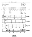
- Each of the q classes of n b differential phases constitutes "a sampling comb", each corresponding to equidistant moments of possible decisions.
- Each comb is identified by the class number 1 to q it represents.
- FIG. 4 gives a digital example of the constitution of sampling combs.
- These sampling combs are offset one from the next by a sampling period.
- the sampling instants, for a level, and these combs are represented in FIG. 4 with the 4 original instants of the calculation of the differential phases constituting them.
- the next step is to "equalize" the qs. n b differential phases thus classified, if necessary (it is for this reason that the corresponding frame on the flow diagram of FIG. 1 is shown in dotted lines).
- certain angular modulations for example the continuous phase frequency modulations called “partial response”, produce phase variations over the duration of a symbol period which depend on several bits; the contribution to the phase variation due to this spread over several bits, assimilated to inter-symbol interference, must be reduced as much as possible before demodulation to allow decision-making. This reduction is obtained by the "equalization" operation which can be interpreted as the search for the symbol that generated the phase variation.
- the next step in the demodulation process consists in correcting the measured phases by assuming that the frequency drift is equal to one of several predefined frequency drifts, distributed to cover the whole range of possible drift. From the evaluation of an expression translating a noise minimization criterion, the supposed bits transmitted under the envisaged conditions are demodulated.
- the values of the predefined frequency drifts are chosen in a number such that the total processing does not occupy too long a time, but makes it possible to scan the most probable possibilities of frequency drifts and to quickly arrive at a good estimate of the real drift. .
- This processing step can be summarized succinctly as follows: a predefined frequency drift value being retained, the equalized differential phases of each of the q sampling combs are reduced by the variation in equalized phase corresponding to the frequency drift envisaged: the sign of the resulting differential phases provides the supposed bit transmitted.
- the predefined frequency drift values are such that the phase rotation generated by these errors must not produce too many erroneous decisions for the evaluation of the noise power: in fact, by the play of a predefined frequency drift, the equalized differential phase sees its sign reverse, the "decision" on the supposed value of the bit is then wrong.
- each set of n b bits makes it possible to calculate the assumed differential phases generated on transmission, that is to say to perform a reconstruction of the assumed differential phases transmitted which would correspond to this set of bits and to evaluate a "noise criterion" as a function of the reconstructed differential phases, of the measured differential phases, and of the assumed drift.
- the next step then consists in choosing the most appropriate frequency drift and set of samples, by minimizing the evaluated noise criterion. This selection can be made first for each drift value between the q possible games, then between the selected games associated with the different drift values. A more precise estimation of the frequency drift is then carried out, step B, from the reconstructed differential phases and the differential phases measured for the set of bits resulting from the selection.
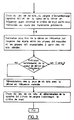
- the last step consists in demodulating the q sets of differential phases (equalized), after correction of these differential phases as a function of the frequency drift estimated more precisely in the previous phase, then in selecting the resulting set of n b bits which minimizes the noise criterion calculated as above by associating with it the corresponding sampling comb which simultaneously gives bit synchronization.
- this last step can only be carried out if the frequency drift is deemed to be estimated with sufficient precision.
- a test intended to verify it is carried out as shown in FIG. 3. If this is not the case, the method can resume at step "A", from a set of predefined drifts distributed in a more close around the estimated drift after the first treatment.
- FIGS. 5 and 6 represent sub-assemblies of the demodulation device.
- FIG. 5 represents a first part of the demodulator.
- the reception chain comprises the HF reception antenna, followed by the HF reception stage, 1, amplifier and filter, followed by the intermediate frequency transposition stage, 2.
- the signal thus transposed into an intermediate frequency is applied to the input of the differential phase generation device 10 which includes a phase measurement circuit, 11 providing a continuous signal characteristic of the phase of the signal applied to its input.
- the output signal of this difference circuit 12 is therefore a continuous signal from which the elementary differential phases d ⁇ i can be taken between instants separated by a sampling period, by means of a sampler 14 controlled by a signal.
- sampling clock H e from a logic control circuit 40 shown in FIG. 6.
- the elementary differential phases resulting from this sampling are transmitted to the input of a delay line 15 with q stages.
- the samples stored in this delay line are transmitted, during the sampling period to an adder 16 which calculates the successive differential phases D ⁇ n corresponding to the phase variations over a period of 1 bit, by shifting each calculation of a sample , by the play of the offset in the delay line.
- the parasitic terms are at least of order 2 in z and z ⁇ 1.
- the demodulator shown in FIG. 5 includes an equalization device 20 corresponding to a modulation in which the phase variation over a period of 1 bit is spread over 3 bits of information.
- This equalization device 20 comprises 2 delay lines of duration equal to 1 bit, 21 and 22 in series; the input of the delay line 21 is connected to a first input of a multiplier 23 whose second input receives information relating to a multiplication coefficient K1.
- the outputs of the delay lines 21 and 22 are respectively connected to the inputs of two multipliers 24 and 25, the other inputs of which receive multiplier coefficients K2 and K3 respectively.
- These coefficients K1 K2 and K3 are directly related to the coefficients - ⁇ , +1, and - ⁇ of the equalization polynomial E (z).
- a referral system 30 makes it possible to constitute the "combs" defined above from the series of equalized phase differential values at the output of the equalization device, these equalized phases being emitted at the rate of the samples.
- This switching device comprises a first cyclic switch with q positions, 31, operating at the rate of the sampling clock H e , and which makes it possible to switch all the equalized differential phases assigned to the same modulo number q, towards the one of q memories, 32 (1), 32 (2) ... 32 (q).
- the outputs of these q memories are connected to corresponding inputs of a switching device 33 with q inputs and an output which is controlled at the rate of the clock bit H b obtained by frequency division by q of the clock d sampling H e in the control circuit 40 (FIG. 6).
- This switching device 33 makes it possible to transfer the equalized differential phases E ⁇ stored in one of the q memories, in packets of n b , and to process them as will be explained below.
- the device carrying out the rest of the processing is shown in FIG. 6: it comprises the logic control circuit 40 which controls the resetting to zero, the writing and reading of the memories, the selection of the frequency drift values, and the switches . To simplify the figure, the corresponding control wires have not been shown. It also comprises a generator of equalized differential phases associated with the predefined frequency drifts, 50, a difference circuit 60, a first input of which is connected to the output of the switching device 33 and the other input of which is connected to the output of the differential phase generator associated with the predefined frequency drifts 50, and which generates the corrected differential phases for each predefined frequency drift value.
- circuit 60 The output of circuit 60 is connected to a decision circuit + 1 / -1, which from each corrected differential phase value decides the value of the corresponding bit assumed to be sent.
- the corresponding decided bit sequences are then stored in one of q memories 72 (1), 72 (2) ... 72 (q) via a cyclic switch with q positions 71, the outputs of these memories being connected to the inputs a switching device with q inputs and 1 output, 73.
- the difference circuit 75 calculates the difference (E ⁇ k ) m - (E ⁇ k ) r - ⁇ ⁇ and a quadratic detector 76 in calculates the square. This detector is followed by an adder 77 which adds this value to the previous value transmitted to an accumulator 78 and reapplied to the adder 77, so as to calculate the noise criterion corresponding to a series of n b decided bits.
- This accumulator is connected to a logic comparison circuit 79, associated with a memory for storing the best result, 80, which compares, for each series of decided bits, the noise criterion calculated with the noise criterion previously stored and the store in its place if it is lower.
- the set of n b bits thus retained is the sequence of the n b bits assumed to be transmitted, available on the "decided bits" output.
- the preserved sampling comb constitutes bit synchronization, each of the instants composing this comb proving to be the best decision time;
- the predefined frequency value adopted turns out to be a rough estimate of the frequency drift.
- FIG. 7 represents the error rate curves as a function of this ratio for different values of uncorrected frequency drifts, 0, 1600 Hz, 3200 Hz, obtained by a conventional demodulation method in the case of an SRC4 demodulation, characterized by a modulation speed of 36 Kbits per second and for a frequency hopping link comprising 18 bits per level.
- the curve obtained by the demodulation method according to the invention with the maximum frequency error previously considered, ie 3200 Hz. It appears that the proposed demodulation method leads to degraded performance only by 1 '' order of 1 dB in the presence of strong frequency drifts compared to the performances obtained in an ideal case in the absence of frequency drift.
- the invention is not limited to the embodiments precisely described and shown.
- the entire demodulation method and device have been described, taking into account the necessary equalization only in the event of intersymbol interference.
- this equalization is not necessary, and the values of predefined frequency drifts result in phase variations which can be deduced directly from the measured differential phases, of course without equalization.
Landscapes
- Engineering & Computer Science (AREA)
- Computer Networks & Wireless Communication (AREA)
- Signal Processing (AREA)
- Digital Transmission Methods That Use Modulated Carrier Waves (AREA)
Claims (8)
- Verfahren zur Demodulation von Signalen mit konstanter Hülle und kontinuierlicher Phase, bei dem in Stufen von nb Bits ein empfangenes Signal numerisch behandelt wird, das in ein Basisband zurückgeführt ist und dessen Phase mit einer bezüglich der Bitperiode Tb überhöhten Abtastrate abgetastet wird, dadurch gekennzeichnet, daß es darauf beruht,- daß in einer ersten Phase q Untereinheiten von nb differentiellen Phasen bei der Bitperiode gemessen werden, und zwar ausgehend von Anfangszeitpunkten, die um Bruchteile Tb/q dieser Periode gegeneinander versetzt sind, um versetzte Abtastkämme mit der Bitperiode zu bilden,- daß in einer zweiten Phase a priori diese Untereinheiten von differentiellen Phasen durch Phasenhübe korrigiert werden, die einer Einheit von d vorbestimmten Frequenzabweichungen zugeordnet sind, um d.q Einheiten von nb korrigierten differentiellen Phasen zu erzeugen, und daß daraus d.q zugeordnete, demodulierte Sätze von nb Bits abgeleitet werden,- daß in einer dritten Phase die differentiellen Phasen wieder hergestellt werden, von denen angenommen wird, daß sie ausgehend von einem jeweiligen demodulierten Satz von nb Bits abgegeben wurden, und daß für jeden der d.q demodulierten Bitsätze ein Geräuschkriterium berechnet wird, das den Satz von wiederhergestellten differentiellen Phasen und den Satz von differentiellen Phasen berücksichtigt, die gemessen und in Abhängigkeit von einer vorbestimmten Abweichung korrigiert wurden,- daß in einer vierten Phase der Satz von nb Bits ausgewählt wird, der das Geräuschkriterium auf ein Minimum herabsetzt, wobei die ihm zugeordnete vorbestimmte Frequenzabweichung einer Grobabschätzung der reellen Abweichung entspricht,- daß in einer vorletzten Phase ausgehend von dem ausgewählten demodulierten Bitsatz eine Endabschätzung der reellen Abweichung mittels Hüben zwischen den gemessenenen differentiellen Phasen und den wiederhergestellten differentiellen Phasen berechnet wird, die diesem Satz von nb Bits zugeordnet sind, und- daß in einer letzten Phase q Sätze von differentiellen Phasen demoduliert werden, nachdem sie um den Phasenhub korrigiert wurden, der der Endabschätzung der reellen Abweichung zugeordnet ist, daß für jeden das Geräuschkriterium berechnet wird, und daß unter den resultierenden Sätzen der ausgewählt wird, der das Geräuschkriterium auf ein Minimum herabsetzt, wobei der ihm zugeordnete Abtastkamm das Synchronisationsbit bildet.
- Verfahren nach Anspruch 1, dadurch gekennzeichnet, daß bei der durch ein Bit bedingten Phasenvariation, die sich über mehrere Bitperioden des abgegebenen Signals erstreckt, die gemessenen differentiellen Phasen in der ersten Phase egalisiert werden, um den Erstreckungseffekt zu vermindern, wobei alle Phasenhübe, die den vorbestimmten Frequenzabweichungen zugeordnet sind, und dann die wiederhergestellten differentiellen Phasen, die während der Behandlung bestimmt wurden, gleichermaßen egalisiert werden.
- Verfahren nach einem der Ansprüche 1 und 2, dadurch gekennzeichnet, daß das Verfahren für die Berechnung der q Untereinheiten von nb differentiellen Phasen bei der Bitperiode vorsieht, daß das Signal in dem Basisband mit der Periode Tb/q abgetastet wird, daß die Variationen von elementaren differentiellen Phasen zwischen aufeinanderfolgenden Abtastwerten gemessen werden, daß nb mal q aufeinanderfolgende elementare differentielle Phasen ausgehend von einem Anfangsabtastwert addiert werden, um eine Untereinheit von nb differentiellen Phasen zu bilden, wobei die anderen Untereinheiten nach einem Versatz des Anfangs eines Abtastwerts auf die gleiche Weise erhalten werden.
- Verfahren nach einem der Ansprüche 1 und 2, dadurch gekennzeichnet, daß die d vorbestimmten Frequenzabweichungen in dem möglichen Frequenzabweichungsbereich verteilt sind.
- Verfahren nach Anspruch 4, dadurch gekennzeichnet, daß am Ende der vierten Phase die Genauigkeit der Grobschätzung der reellen Abweichung getestet wird, und daß dann, wenn die Genauigkeit unzureichend ist, das Verfahren mit seiner zweiten Phase ausgehend von einer anderen Einheit vorbestimmter Frequenzabweichungen wiederaufgenommen wird, die um den zuvor zurückbehaltenen Grobschätzwert verteilt sind.
- Verfahren nach einem der Ansprüche 1 und 2, dadurch gekennzeichnet, daß für einen Satz von demodulierten Bits, der eine Frequenzabweichung berücksichtigt, das Geräuschkriterium der Mittelwert der quadratischen Hübe ist, die zwischen den gemessenen differentiellen Phasen, die durch den Phasenhub korrigiert wurden, der dieser Frequenzabweichung zugeordnet ist, und den entsprechenden wiederhergestellten differentiellen Phasen vorliegen.
- Vorrichtung zur Demodulation von Signalen mit konstanter Hülle und kontinuierlicher Phase, zur Durchführung des Verfahrens gemäß einem der vorhergehenden Ansprüche, dadurch gekennzeichnet, daß sie, durch eine Steuerschaltung (40) gesteuert, folgendes enthält:- eine Schaltung (10) zum Messen von q Untereinheiten von nb differentiellen Phasen ausgehend von einem Signal, das für die Phase eines empfangenen, zu demodulierenden Signals charakteristisch ist, das mit der Periode Tb/q abgetastet wird,- eine Schaltung (20) zum Egalisieren der differentiellen Phasen, die erforderlichenfalls eine Linearkombination von aufeinanderfolgenden differentiellen Phasen durchführt, um den Erstreckungseffekt, sofern vorhanden, zu verringern,- eine Verzweigungs- und Speicherschaltung (30) zum Bilden von Untergruppen gemessener und egalisierter differentieller Phasen entsprechend den um Bruchteile einer Bitperiode versetzten Abtastkämmen,- einen Generator (50) von egalisierten differentiellen Phasen, die der Einheit von vorbestimmten Frequenzabweichungen zugeordnet sind,- eine Differenzschaltung (60), die mit den Ausgängen der Verzweigungs- und Speicherschaltung (30) und des Generators (50) verbunden ist,- eine Schaltung (65) für eine Entscheidung über den Wert der Bits, die mit einem Ausgang einerseits mit einer Verzweigungs- und Speicherschaltung für die demodulierten Bits und andererseits einer Schaltung (74) zur Wiederherstellung der Phasen verbunden ist, von denen angenommen wird, daß sie in Abhängigkeit von diesen Bits abgegeben wurden,- eine Schaltung (75 - 78) zum Berechnen eines Geräuschkriteriums, die mit dem Ausgang der Differenzschaltung (60) und dem der Schaltung (74) zur Wiederherstellung der Phasen verbunden ist, von denen angenommen wird, daß sie abgegeben wurden, und- eine Vergleichschaltung (79, 80) mit Speicher, um unter den Sätzen von gespeicherten Bits den auszusuchen, der das Geräuschkriterium auf ein Minimum herabsetzt.
- Demodulationsvorrichtung nach Anspruch 7, dadurch gekennzeichnet, daß die Funktionen zum Steuern, Berechnen, Speichern, Entscheiden und Auswählen durch einen Mikroprozessor ausgeführt werden, der die numerischen Werte von differentiellen Phasen verarbeitet.
Applications Claiming Priority (2)
| Application Number | Priority Date | Filing Date | Title |
|---|---|---|---|
| FR8809731A FR2635420B1 (fr) | 1988-07-19 | 1988-07-19 | Procede et dispositif de demodulation de signaux a enveloppe constante et phase continue modules angulairement par un train de symboles binaires, tolerant les derives de frequence |
| FR8809731 | 1988-07-19 |
Publications (2)
| Publication Number | Publication Date |
|---|---|
| EP0352159A1 EP0352159A1 (de) | 1990-01-24 |
| EP0352159B1 true EP0352159B1 (de) | 1993-08-04 |
Family
ID=9368540
Family Applications (1)
| Application Number | Title | Priority Date | Filing Date |
|---|---|---|---|
| EP89401886A Expired - Lifetime EP0352159B1 (de) | 1988-07-19 | 1989-06-30 | Frequenzabweichungstolerierendes Verfahren und Vorrichtung zur Demodulation von, durch eine Binärsymbolreihe, winkelmodulierten Signalen mit konstanter Umhüllung und kontinuierlicher Phase |
Country Status (4)
| Country | Link |
|---|---|
| US (1) | US4945312A (de) |
| EP (1) | EP0352159B1 (de) |
| DE (1) | DE68908038T2 (de) |
| FR (1) | FR2635420B1 (de) |
Families Citing this family (14)
| Publication number | Priority date | Publication date | Assignee | Title |
|---|---|---|---|---|
| US5228062A (en) * | 1990-04-16 | 1993-07-13 | Telebit Corporation | Method and apparatus for correcting for clock and carrier frequency offset, and phase jitter in multicarrier modems |
| US5194287A (en) * | 1990-07-24 | 1993-03-16 | Conagra, Inc. | Wheat milling process and milled wheat product |
| US5141764A (en) * | 1990-07-24 | 1992-08-25 | Conagra, Inc. | Wheat milling process |
| FR2735872B1 (fr) * | 1995-06-23 | 1997-08-08 | Thomson Csf | Systeme de navigation permettant la coordination en temps reel du deplacement de mobiles evoluant sans etre a vue directe |
| US6212245B1 (en) * | 1995-07-13 | 2001-04-03 | Canon Kabushiki Kaisha | Communication apparatus |
| FR2738383B1 (fr) * | 1995-09-05 | 1997-10-03 | Thomson Csf | Procede de quantification vectorielle de vocodeurs bas debit |
| FR2743893B1 (fr) * | 1996-01-23 | 1998-03-06 | Thomson Csf | Dispositif de radiocommunication et de localisation |
| US5812604A (en) * | 1996-07-16 | 1998-09-22 | Scientific-Atlanta, Inc. | Constant envelope continuous phase frequency shift key modulation apparatus and method at radio frequencies |
| FR2758673B1 (fr) * | 1997-01-21 | 1999-04-23 | Thomson Csf | Procede auto-adaptatif de transmission de donnees et dispositif de mise en oeuvre |
| FR2778041A1 (fr) * | 1998-04-24 | 1999-10-29 | Thomson Csf | Procede de neutrodynage du tube d'un emetteur |
| FR2788390B1 (fr) | 1999-01-12 | 2003-05-30 | Thomson Csf | Emetteur de radiodiffusion en ondes courtes a haut rendement optimise pour les emissions de type numerique |
| FR2790343B1 (fr) | 1999-02-26 | 2001-06-01 | Thomson Csf | Systeme pour l'estimation du gain complexe d'un canal de transmission |
| FR2799592B1 (fr) | 1999-10-12 | 2003-09-26 | Thomson Csf | Procede de construction et de codage simple et systematique de codes ldpc |
| US6700928B1 (en) | 2000-05-11 | 2004-03-02 | The Boeing Company | Tetrahedron modem |
Family Cites Families (1)
| Publication number | Priority date | Publication date | Assignee | Title |
|---|---|---|---|---|
| US3938052A (en) * | 1974-05-09 | 1976-02-10 | Teletype Corporation | Digital demodulator for phase-modulated waveforms |
-
1988
- 1988-07-19 FR FR8809731A patent/FR2635420B1/fr not_active Expired - Lifetime
-
1989
- 1989-06-30 EP EP89401886A patent/EP0352159B1/de not_active Expired - Lifetime
- 1989-06-30 DE DE89401886T patent/DE68908038T2/de not_active Expired - Fee Related
- 1989-07-17 US US07/380,537 patent/US4945312A/en not_active Expired - Fee Related
Also Published As
| Publication number | Publication date |
|---|---|
| US4945312A (en) | 1990-07-31 |
| EP0352159A1 (de) | 1990-01-24 |
| FR2635420B1 (fr) | 1990-10-19 |
| DE68908038D1 (de) | 1993-09-09 |
| FR2635420A1 (fr) | 1990-02-16 |
| DE68908038T2 (de) | 1993-11-18 |
Similar Documents
| Publication | Publication Date | Title |
|---|---|---|
| EP0125722B1 (de) | Schaltungsanordnung zur kombinierten adaptativen Entzerrung und Demodulation | |
| EP0352159B1 (de) | Frequenzabweichungstolerierendes Verfahren und Vorrichtung zur Demodulation von, durch eine Binärsymbolreihe, winkelmodulierten Signalen mit konstanter Umhüllung und kontinuierlicher Phase | |
| EP0013343B1 (de) | Verfahren und Vorrichtung zur Auffindung einer Pseudo-Zufallsfolge von 0 Grad- und 180 Grad-Phasenänderungen der Trägerwelle in einem Datenempfänger | |
| FR2623669A1 (fr) | Appareil et procede d'egalisation pour la transmission de donnees | |
| EP0178720A1 (de) | Einrichtung zum Empfang von digitalen Daten mit einer adaptiven Taktrückgewinnungsschaltung | |
| EP0505223A1 (de) | Vorrichtung zur digitalen Datenübertragung über eine Leitung des Stromnetzes | |
| EP2915302B9 (de) | Verfahren und vorrichtung zur demodulation von q-gfsk signalen | |
| EP0329537A1 (de) | Übertragungssystem mit MSK-Modulation und kohärenter differentieller Detektion | |
| EP0017716B1 (de) | Verfahren zur Anfangseinstellung eines adaptiven Entzerrers ausgehend von einem unbekannten Datensignal in einem Übertragungssystem mit Doppelseitenbandmodulation und Quadraturträgern | |
| EP0762703A1 (de) | Demodulation eines Mehrträgersignals mit Verringerung von weissen Frequenzstörungen | |
| EP0376250B1 (de) | Selbst-adaptive Entzerrungseinrichtung für eine differentielle kohärente Demodulationsanordnung | |
| EP0073869A1 (de) | Einrichtung zum Datenempfang mit einem hörerseitigen Echokompensator | |
| EP0230900B1 (de) | Taktwiedergewinnungseinrichtung | |
| FR2794589A1 (fr) | Procede de communications radiomobiles amrt iteratif | |
| WO1984004640A1 (fr) | Procede de demodulation non-coherente d'un signal module lineairement a energie par symbole constante et demodulateur pour la mise en oeuvre dudit procede | |
| EP0080544B1 (de) | Verfahren zum Empfangen eines Datensignals mit Doppelseitenbandmodulation und Quadraturträgern | |
| EP0039980A1 (de) | Adaptives digitales Datenempfangssystem mit Kompensation der durch den Datenübertragungskanal verursachten Amplituden- und Phasenverzerrungen | |
| EP0035295B1 (de) | Verfahren zur Regelung der Phase des Taktgenerators eines Empfangssystems für digitale Daten, Phasenrückgewinnungsschaltung zur Durchführung dieses Verfahrens und Empfangssystem für digitale Daten mit dieser Schaltung | |
| CA1312657C (fr) | Dispositif de synchronisation en modulation de phase a quatre etats decalee | |
| EP0094040B1 (de) | System zur synchronen Datenübertragung mit Hilfe eines amplitudenmodulierten Trägers konstanter Hüllkurve | |
| EP0792053A1 (de) | Digitales Übertragungssystem zur Übertragung mittels kontinuierlicher Phasenmodulation | |
| FR2786965A1 (fr) | Procede de recuperation de porteuse de signal | |
| EP0127544B1 (de) | Echokompensator mit einem adaptiven digitalen Filter für ein Übertragungssystem | |
| EP0494003B1 (de) | Empfangsanordnung zur Verarbeitung von auf verschiedenen Wegen empfangenen Signalen | |
| EP0648037A1 (de) | Phasenabgleich im Basisband |
Legal Events
| Date | Code | Title | Description |
|---|---|---|---|
| PUAI | Public reference made under article 153(3) epc to a published international application that has entered the european phase |
Free format text: ORIGINAL CODE: 0009012 |
|
| AK | Designated contracting states |
Kind code of ref document: A1 Designated state(s): DE GB IT |
|
| 17P | Request for examination filed |
Effective date: 19900621 |
|
| 17Q | First examination report despatched |
Effective date: 19920708 |
|
| GRAA | (expected) grant |
Free format text: ORIGINAL CODE: 0009210 |
|
| AK | Designated contracting states |
Kind code of ref document: B1 Designated state(s): DE GB IT |
|
| ITF | It: translation for a ep patent filed | ||
| REF | Corresponds to: |
Ref document number: 68908038 Country of ref document: DE Date of ref document: 19930909 |
|
| GBT | Gb: translation of ep patent filed (gb section 77(6)(a)/1977) |
Effective date: 19931014 |
|
| RAP2 | Party data changed (patent owner data changed or rights of a patent transferred) |
Owner name: THOMSON-CSF |
|
| PGFP | Annual fee paid to national office [announced via postgrant information from national office to epo] |
Ref country code: GB Payment date: 19940520 Year of fee payment: 6 Ref country code: DE Payment date: 19940520 Year of fee payment: 6 |
|
| PLBE | No opposition filed within time limit |
Free format text: ORIGINAL CODE: 0009261 |
|
| STAA | Information on the status of an ep patent application or granted ep patent |
Free format text: STATUS: NO OPPOSITION FILED WITHIN TIME LIMIT |
|
| 26N | No opposition filed | ||
| PG25 | Lapsed in a contracting state [announced via postgrant information from national office to epo] |
Ref country code: GB Effective date: 19950630 |
|
| GBPC | Gb: european patent ceased through non-payment of renewal fee |
Effective date: 19950630 |
|
| PG25 | Lapsed in a contracting state [announced via postgrant information from national office to epo] |
Ref country code: DE Effective date: 19960301 |
|
| PG25 | Lapsed in a contracting state [announced via postgrant information from national office to epo] |
Ref country code: IT Free format text: LAPSE BECAUSE OF NON-PAYMENT OF DUE FEES;WARNING: LAPSES OF ITALIAN PATENTS WITH EFFECTIVE DATE BEFORE 2007 MAY HAVE OCCURRED AT ANY TIME BEFORE 2007. THE CORRECT EFFECTIVE DATE MAY BE DIFFERENT FROM THE ONE RECORDED. Effective date: 20050630 |