EP0352204A1 - Verfahren und Vorrichtung zum Befestigen von Landungsbrücken auf Pfählen - Google Patents
Verfahren und Vorrichtung zum Befestigen von Landungsbrücken auf Pfählen Download PDFInfo
- Publication number
- EP0352204A1 EP0352204A1 EP89430019A EP89430019A EP0352204A1 EP 0352204 A1 EP0352204 A1 EP 0352204A1 EP 89430019 A EP89430019 A EP 89430019A EP 89430019 A EP89430019 A EP 89430019A EP 0352204 A1 EP0352204 A1 EP 0352204A1
- Authority
- EP
- European Patent Office
- Prior art keywords
- piles
- pile
- support
- wharf
- water
- Prior art date
- Legal status (The legal status is an assumption and is not a legal conclusion. Google has not performed a legal analysis and makes no representation as to the accuracy of the status listed.)
- Granted
Links
- 238000000034 method Methods 0.000 title claims abstract description 11
- XLYOFNOQVPJJNP-UHFFFAOYSA-N water Substances O XLYOFNOQVPJJNP-UHFFFAOYSA-N 0.000 claims abstract description 32
- 238000009434 installation Methods 0.000 claims abstract description 16
- 238000002513 implantation Methods 0.000 claims description 8
- 229910052751 metal Inorganic materials 0.000 claims description 8
- 239000002184 metal Substances 0.000 claims description 8
- 238000004873 anchoring Methods 0.000 claims description 7
- 238000003032 molecular docking Methods 0.000 claims description 7
- 239000002023 wood Substances 0.000 claims description 7
- 230000003100 immobilizing effect Effects 0.000 claims description 6
- 238000006243 chemical reaction Methods 0.000 claims description 3
- 238000009826 distribution Methods 0.000 claims description 3
- 230000035515 penetration Effects 0.000 claims description 3
- 238000003825 pressing Methods 0.000 claims description 3
- 230000008569 process Effects 0.000 claims description 3
- 239000011347 resin Substances 0.000 claims description 2
- 229920005989 resin Polymers 0.000 claims description 2
- 125000006850 spacer group Chemical group 0.000 claims description 2
- 238000006073 displacement reaction Methods 0.000 claims 1
- 238000004519 manufacturing process Methods 0.000 abstract description 5
- 239000000463 material Substances 0.000 description 6
- 229910000831 Steel Inorganic materials 0.000 description 5
- 239000010959 steel Substances 0.000 description 5
- 229910052782 aluminium Inorganic materials 0.000 description 4
- XAGFODPZIPBFFR-UHFFFAOYSA-N aluminium Chemical compound [Al] XAGFODPZIPBFFR-UHFFFAOYSA-N 0.000 description 4
- 238000011161 development Methods 0.000 description 4
- 238000012423 maintenance Methods 0.000 description 3
- 238000002360 preparation method Methods 0.000 description 3
- 230000008901 benefit Effects 0.000 description 2
- 238000013461 design Methods 0.000 description 2
- 230000001932 seasonal effect Effects 0.000 description 2
- 239000002689 soil Substances 0.000 description 2
- -1 (such as alumnium Substances 0.000 description 1
- AZDRQVAHHNSJOQ-UHFFFAOYSA-N alumane Chemical group [AlH3] AZDRQVAHHNSJOQ-UHFFFAOYSA-N 0.000 description 1
- 238000010009 beating Methods 0.000 description 1
- 230000000903 blocking effect Effects 0.000 description 1
- 230000015556 catabolic process Effects 0.000 description 1
- 239000002131 composite material Substances 0.000 description 1
- 238000010276 construction Methods 0.000 description 1
- 238000005260 corrosion Methods 0.000 description 1
- 230000007797 corrosion Effects 0.000 description 1
- 238000006731 degradation reaction Methods 0.000 description 1
- 238000007689 inspection Methods 0.000 description 1
- 230000002427 irreversible effect Effects 0.000 description 1
- 238000012986 modification Methods 0.000 description 1
- 230000004048 modification Effects 0.000 description 1
- 230000008439 repair process Effects 0.000 description 1
- 230000000284 resting effect Effects 0.000 description 1
- 238000012360 testing method Methods 0.000 description 1
Images

Classifications
-
- E—FIXED CONSTRUCTIONS
- E02—HYDRAULIC ENGINEERING; FOUNDATIONS; SOIL SHIFTING
- E02B—HYDRAULIC ENGINEERING
- E02B17/00—Artificial islands mounted on piles or like supports, e.g. platforms on raisable legs or offshore constructions; Construction methods therefor
- E02B17/04—Equipment specially adapted for raising, lowering, or immobilising the working platform relative to the supporting construction
- E02B17/08—Equipment specially adapted for raising, lowering, or immobilising the working platform relative to the supporting construction for raising or lowering
-
- E—FIXED CONSTRUCTIONS
- E02—HYDRAULIC ENGINEERING; FOUNDATIONS; SOIL SHIFTING
- E02B—HYDRAULIC ENGINEERING
- E02B17/00—Artificial islands mounted on piles or like supports, e.g. platforms on raisable legs or offshore constructions; Construction methods therefor
- E02B17/02—Artificial islands mounted on piles or like supports, e.g. platforms on raisable legs or offshore constructions; Construction methods therefor placed by lowering the supporting construction to the bottom, e.g. with subsequent fixing thereto
- E02B17/021—Artificial islands mounted on piles or like supports, e.g. platforms on raisable legs or offshore constructions; Construction methods therefor placed by lowering the supporting construction to the bottom, e.g. with subsequent fixing thereto with relative movement between supporting construction and platform
-
- E—FIXED CONSTRUCTIONS
- E02—HYDRAULIC ENGINEERING; FOUNDATIONS; SOIL SHIFTING
- E02B—HYDRAULIC ENGINEERING
- E02B17/00—Artificial islands mounted on piles or like supports, e.g. platforms on raisable legs or offshore constructions; Construction methods therefor
- E02B17/04—Equipment specially adapted for raising, lowering, or immobilising the working platform relative to the supporting construction
- E02B17/08—Equipment specially adapted for raising, lowering, or immobilising the working platform relative to the supporting construction for raising or lowering
- E02B17/0809—Equipment specially adapted for raising, lowering, or immobilising the working platform relative to the supporting construction for raising or lowering the equipment being hydraulically actuated
-
- E—FIXED CONSTRUCTIONS
- E02—HYDRAULIC ENGINEERING; FOUNDATIONS; SOIL SHIFTING
- E02B—HYDRAULIC ENGINEERING
- E02B17/00—Artificial islands mounted on piles or like supports, e.g. platforms on raisable legs or offshore constructions; Construction methods therefor
- E02B17/04—Equipment specially adapted for raising, lowering, or immobilising the working platform relative to the supporting construction
- E02B17/08—Equipment specially adapted for raising, lowering, or immobilising the working platform relative to the supporting construction for raising or lowering
- E02B17/0836—Equipment specially adapted for raising, lowering, or immobilising the working platform relative to the supporting construction for raising or lowering with climbing jacks
- E02B17/0854—Equipment specially adapted for raising, lowering, or immobilising the working platform relative to the supporting construction for raising or lowering with climbing jacks with clamping wedges, eccentric clamping devices and so on
-
- E—FIXED CONSTRUCTIONS
- E02—HYDRAULIC ENGINEERING; FOUNDATIONS; SOIL SHIFTING
- E02B—HYDRAULIC ENGINEERING
- E02B3/00—Engineering works in connection with control or use of streams, rivers, coasts, or other marine sites; Sealings or joints for engineering works in general
- E02B3/04—Structures or apparatus for, or methods of, protecting banks, coasts, or harbours
- E02B3/06—Moles; Piers; Quays; Quay walls; Groynes; Breakwaters ; Wave dissipating walls; Quay equipment
- E02B3/068—Landing stages for vessels
-
- E—FIXED CONSTRUCTIONS
- E02—HYDRAULIC ENGINEERING; FOUNDATIONS; SOIL SHIFTING
- E02B—HYDRAULIC ENGINEERING
- E02B17/00—Artificial islands mounted on piles or like supports, e.g. platforms on raisable legs or offshore constructions; Construction methods therefor
- E02B2017/0056—Platforms with supporting legs
-
- Y—GENERAL TAGGING OF NEW TECHNOLOGICAL DEVELOPMENTS; GENERAL TAGGING OF CROSS-SECTIONAL TECHNOLOGIES SPANNING OVER SEVERAL SECTIONS OF THE IPC; TECHNICAL SUBJECTS COVERED BY FORMER USPC CROSS-REFERENCE ART COLLECTIONS [XRACs] AND DIGESTS
- Y02—TECHNOLOGIES OR APPLICATIONS FOR MITIGATION OR ADAPTATION AGAINST CLIMATE CHANGE
- Y02A—TECHNOLOGIES FOR ADAPTATION TO CLIMATE CHANGE
- Y02A10/00—TECHNOLOGIES FOR ADAPTATION TO CLIMATE CHANGE at coastal zones; at river basins
- Y02A10/11—Hard structures, e.g. dams, dykes or breakwaters
Definitions
- the present invention relates to a method and devices for implantation on piers of wharves.
- the technical sector of the invention is that of the manufacture and installation of wharves intended for the docking and mooring of boats.
- One of the applications of the invention is the arrangement of a body of water, of the port enclosure type or sheltered mooring area, to accommodate pleasure boats.
- wharves intended for the development of ports, whose design is similar to that of water crossing bridges and there are many companies in each country, which manufacture and install these equipments.
- These various types of wharves can be classified into two main categories by type: that of so-called floating wharves and that of so-called fixed wharves;
- sub-categories one by nature of the material used, which can be mainly wood, steel, aluminum or concrete, the other by the anchoring means which can be on chains and dead bodies, on piles driven into the ground or on supports placed at the bottom.
- Floating wharves of which the supporting structure and the float part are a combination of materials or made of one, for example: - floats and structures in aluminum (or steel), upper decking in wood; - composite material floats, aluminum structure, wooden decking; - floats also structure in concrete;
- the advantage of this solution is to be able to choose light materials, (such as alumnium, wood and laminate) and therefore reduce investments.
- the concrete solution is increasingly discarded, because it is heavy and expensive, and difficult to hold in place by anchors, because the inertia is important.
- Pile anchoring also requires fairly heavy barges for their threshing in the ground; the freedom of movement left to the floating structures is a cause of significant wear and therefore of rapid degradation, and the floats lack reliability and tightness over time.
- the present invention is the result of studies and tests carried out in this direction, constituting a new category of wharves.
- the problem is to be able to manufacture resistant wharves, which can in particular support heavy loads and install them in any port or semi-sheltered area, without preparation of the bottom of the water or use of a large pontoon-barge, and which can be recovered and / or easily and quickly maintained, so that even if the cost of the initial investment is relatively high, it is recovered by reducing the installation and maintenance means.
- a device for installing on pile piles comprising a rectangular and floating structure, characterized in that said structure is of box type and comprises at least four support guides, distributed on both sides , which allow the docking of ships, and each receiving a pile, able to slide freely inside, which piles are of length greater than the water depth of the chosen anchoring site, increased by the height above the water required to lift said structure, and the lower end of which is provided with a support sole, associated with an embedding punch adapted to the nature of the ground so that these piles support the structure positioned horizontally above the water level, and comprise at least one mechanical means making it possible to immobilize them relative to said support guides.
- the result is a new method and device for implantation on piers.
- the implementation of the present invention is done directly from the floating wharf considered, which therefore serves as a support platform for its own implantation, thus reducing the operating costs.
- the driving in of the piles can be done by simple pressing of the pontoon itself or if the weight of the pontoon is not sufficient for any additional weight possible using a known material, for example by beating or by vibrations.
- the wharf is a concrete box making it possible to support large loads and to have good stability on the piles. This is ensured, in all cases, by the embedding of the piles in their guides-supports integral with the structure.
- the whole forms a non-deformable frame, locked in position and sunk into the ground, like a table on its four legs.
- the four piles can serve, for example, as a support base for lighting or other bollards, and their immobilization relative to the structure of the wharf can be provided reversibly, so to be able to slide the structure down again along the piles until it becomes buoyant again.
- the piles can then be raised from the ground and the wharf recovered by towing.
- This type of mobile installation is very interesting for seasonal installations in semi-sheltered areas, such as beaches or bays.
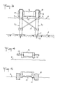
- Figure 1 is a top view of a wharf according to the invention and a first embodiment with a concrete structure.
- This structure integrates, on the one hand, a floating box 15, in the axial central part, and four support guides 31, located two by two, on either side of the central box. The whole constitutes a single integrated element 11 in concrete.
- the upper part of the waterproof box 15 is closed by a 91 floor, which may consist of a concrete slab ensuring the tightness of the box up with possible inspection hatches and, as the case may be, a floor in wood placed on top.
- the four 31 guides each receive a 21 pile, sliding inside as described in Figure 2. Finally on the box can be fixed various rings or lugs 14, allowing the mooring of said ships.
- Figure 2 is a vertical and longitudinal sectional view along the plane AA referenced in Figure 1, of a typical wharf with concrete structure.
- the floating box 15 is shown in buoyancy on the surface 6 of the water.
- the piles 21 are raised to the high position, so that the lower points 12 are immersed in a shallow draft, under the box.
- the piles descend by sliding inside their guides 31, until their point 12 comes into contact with the bottom 4 by their own weight , and whatever the slope and the nature of the bottom which therefore requires no preparation.
- the piles are then more or less submerged according to the depth of water and, to ensure their penetration into the ground so to obtain a sufficient support reaction to then support all the vertical and horizontal forces which the landing must undergo, any means of driving on each pile can be used.
- the structure is then suspended from the four piles by any lifting means 5, such as, for example, systems with jacks, moving self-locking collars around the piles, or simple hoists.
- This lifting means 5 and bearing on the piles 2 transmits part of the weight of the wharf on each of said piles; it can be the same as the one used to push in each of these as shown above.
- the support, driving and / or lifting means are dismantled to be transferred to another wharf and to be reused.
- the boats can then come to dock or moor on the mooring cleats 14 and the passengers can access on board by the floor 13, fixed against the walls of the box 15 at a level lower than the floor 91.
- the height of the guides 31 as well as all the structural elements are determined in particular as a function of the efforts of embedding the piles 21 in these guides, taking into account the lateral loads which the wharf must bear, the dimensions of the piles themselves, their sinking into the ground and the water level.
- Figure 3 is a vertical and cross-sectional view along the plane BB referenced in Figure 1, of a typical wharf in concrete structure.
- the piles are shown here, for example driven into a fairly hard soil 4, in which the point 12 is just embedded up to the level of the sole 11.
- the piles 21 are immobilized and blocked relative to the guide 31 by three means which can be used jointly not safety, but can be used independently for a temporary installation for example, and other means can be used also.
- - Clamps 71 are fixed around each pile, including at least one under the guides 31 which can come to rest on it. Four other collars can be fixed at a level lower than the previous ones and connected together by any spacer system such as connecting bars 17 to stiffen the entire table thus formed and relieve the embedding of the piles 21 in the guides 31 .
- - A stop 16 covers each pile at the top, after having cut the ends of these at the same level.
- These four stops are fixed by any means of the bolt type, for example, to the 31 guides therefore provide support on the pile head and form a sort of cap which can be closed and used as a support;
- -A resin 17 is poured between the guides and the piles to stick to each other and take up the forces. especially for permanent settlements, because this bonding is the only practically irreversible one. It also removes relative, and therefore avoids possible vibrations and prevents internal corrosion.
- the bottom of the box 15 is thus put out of water above the surface 6 and the concrete structure of the wharf is no longer submerged and has better resistance over time.
- the 21 piles can preferably be metallic.
- Figure 4 is a vertical and cross-sectional view along the plane CC referenced in Figure 1 between two piles of a typical wharf, having a concrete structure.
- the figure shows the box 15, positioned above the water, as described above, but the floor 91 is then high enough, due to the volume of said box which must be large enough to ensure the buoyancy of the together in case of towing.
- Figure 5 is a vertical and cross sectional view between two piles of a concrete structure wharf, in a floating towing position. If the structure of the wharf equipped with its stakes and its installation material, is too heavy for the proper buoyancy of the box 15, and in order not to increase it too much, use is made during the towing and setting up phase. place, additional buoyancy boxes 18, fixed on either side of the central box 15 of the wharf structure in place of the floors 13 described in FIG. 4.
- This catamaran or trimaran configuration provides the necessary buoyancy and stability during the critical towing phases, especially if you have to pass through a sheltered area.
- the additional boxes 18 are then dismantled and recovered with the rest of the equipment necessary for installation and replaced by the floors 13, without any particular handling means, above all if we define the volume of these boxes so that they are just floating alone and without effort on their fastening system 21, when box 15 is in its final position.
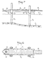
- Figure 6 is a top view of a wharf according to the invention and a second embodiment with a metal box structure and Figure 7 is a side view of this wharf.
- This metal box 19 may be a closed rectangular frame, as shown in the figure, but all other equivalent embodiments are possible.
- the piles 22 are inserted into the ground 4, as described in the previous figure and are blocked relative to the guides 32 so as to maintain said horizontal structure above the water level 6, by any type of rod system 72 , threaded through the pile and overflowing on both sides to bear on the support guide.
- the floor 92 is produced by a wooden decking resting on a frame 20, itself fixed on the box 19 and able to receive, for example, the rings and the mooring cleats 14.
- the wharf thus installed can be connected in a known manner, on the one hand, to other wharves placed against it and made integral by connecting chains 8 and, on the other hand, to other structures or to the bank by an articulated gangway 10, of any known type.
- This type of metal wharf is relatively light compared to those in concrete structure and are easier to install. Conversely, its stability and resistance are lower.
Landscapes
- Engineering & Computer Science (AREA)
- General Engineering & Computer Science (AREA)
- Mechanical Engineering (AREA)
- Civil Engineering (AREA)
- Structural Engineering (AREA)
- Environmental & Geological Engineering (AREA)
- Ocean & Marine Engineering (AREA)
- Bridges Or Land Bridges (AREA)
- Revetment (AREA)
Applications Claiming Priority (2)
| Application Number | Priority Date | Filing Date | Title |
|---|---|---|---|
| FR8810094 | 1988-07-22 | ||
| FR8810094A FR2634504B1 (fr) | 1988-07-22 | 1988-07-22 | Procede et dispositif d'implantation sur pieux d'appontements |
Publications (2)
| Publication Number | Publication Date |
|---|---|
| EP0352204A1 true EP0352204A1 (de) | 1990-01-24 |
| EP0352204B1 EP0352204B1 (de) | 1993-01-13 |
Family
ID=9368805
Family Applications (1)
| Application Number | Title | Priority Date | Filing Date |
|---|---|---|---|
| EP89430019A Expired - Lifetime EP0352204B1 (de) | 1988-07-22 | 1989-07-18 | Verfahren und Vorrichtung zum Befestigen von Landungsbrücken auf Pfählen |
Country Status (4)
| Country | Link |
|---|---|
| EP (1) | EP0352204B1 (de) |
| DE (1) | DE68904369D1 (de) |
| ES (1) | ES2039087T3 (de) |
| FR (1) | FR2634504B1 (de) |
Cited By (11)
| Publication number | Priority date | Publication date | Assignee | Title |
|---|---|---|---|---|
| DE4431081C1 (de) * | 1994-09-01 | 1996-04-25 | Awu Consult Ingenieurgesellsch | Schwimmfähiges Wellenschutzsegment und Verfahren zur Herstellung einer Wellenschutzwand |
| FR2881447A1 (fr) * | 2005-01-28 | 2006-08-04 | Satob Sa | Plate-forme marine |
| CN109268251A (zh) * | 2018-09-13 | 2019-01-25 | 中蓝长化工程科技有限公司 | 一种防倾斜浮箱采卤泵站 |
| CN112278154A (zh) * | 2020-10-23 | 2021-01-29 | 中船黄埔文冲船舶有限公司 | 一种十字形缆桩 |
| CN113136853A (zh) * | 2021-05-14 | 2021-07-20 | 中交第二航务工程局有限公司 | 一种库区裸岩群桩基础装配式钻孔平台及工艺 |
| CN114922153A (zh) * | 2022-07-21 | 2022-08-19 | 华能山西综合能源有限责任公司 | 一种用于风电机组安装的可调节平台 |
| CN114960740A (zh) * | 2022-05-30 | 2022-08-30 | 山东电力工程咨询院有限公司 | 一种桩基固定式支撑结构、海上漂浮式光伏电站及方法 |
| CN115538375A (zh) * | 2022-10-21 | 2022-12-30 | 中交第三航务工程勘察设计院有限公司 | 一种装配式高桩码头结构及其施工方法 |
| CN117598230A (zh) * | 2023-12-07 | 2024-02-27 | 武汉听涛海洋工程有限责任公司 | 一种可自浮重力压入式定位桩及插桩式养殖网箱 |
| CN118148093A (zh) * | 2024-04-16 | 2024-06-07 | 滨州市水利工程有限公司 | 一种水利水面风电深水辅助安装平台 |
| US12338593B2 (en) | 2022-07-21 | 2025-06-24 | Huaneng Shanxi Comprehensive Energy Co. Ltd. | Adjustable platform for installing wind turbine generator |
Citations (5)
| Publication number | Priority date | Publication date | Assignee | Title |
|---|---|---|---|---|
| US2657540A (en) * | 1948-06-14 | 1953-11-03 | John B Templeton | Method of erecting and positioning marine structures |
| GB1220689A (en) * | 1967-12-29 | 1971-01-27 | Nederlandse Offshore Co | Method and apparatus for the construction of an offshore platform |
| US3572045A (en) * | 1968-10-15 | 1971-03-23 | Clifford L Owen | Pier assembly |
| GB1523585A (en) * | 1975-10-28 | 1978-09-06 | Brewerton R W | Offshore platforms |
| FR2441019A1 (fr) * | 1978-11-09 | 1980-06-06 | Lapaix Andre | Barge destinee a former un appontement ou element de quai d'accostage |
Family Cites Families (1)
| Publication number | Priority date | Publication date | Assignee | Title |
|---|---|---|---|---|
| US2589146A (en) * | 1949-10-06 | 1952-03-11 | Charles T Samuelson | Submersible deepwater drilling apparatus |
-
1988
- 1988-07-22 FR FR8810094A patent/FR2634504B1/fr not_active Expired - Lifetime
-
1989
- 1989-07-18 EP EP89430019A patent/EP0352204B1/de not_active Expired - Lifetime
- 1989-07-18 DE DE8989430019T patent/DE68904369D1/de not_active Expired - Lifetime
- 1989-07-18 ES ES198989430019T patent/ES2039087T3/es not_active Expired - Lifetime
Patent Citations (5)
| Publication number | Priority date | Publication date | Assignee | Title |
|---|---|---|---|---|
| US2657540A (en) * | 1948-06-14 | 1953-11-03 | John B Templeton | Method of erecting and positioning marine structures |
| GB1220689A (en) * | 1967-12-29 | 1971-01-27 | Nederlandse Offshore Co | Method and apparatus for the construction of an offshore platform |
| US3572045A (en) * | 1968-10-15 | 1971-03-23 | Clifford L Owen | Pier assembly |
| GB1523585A (en) * | 1975-10-28 | 1978-09-06 | Brewerton R W | Offshore platforms |
| FR2441019A1 (fr) * | 1978-11-09 | 1980-06-06 | Lapaix Andre | Barge destinee a former un appontement ou element de quai d'accostage |
Cited By (11)
| Publication number | Priority date | Publication date | Assignee | Title |
|---|---|---|---|---|
| DE4431081C1 (de) * | 1994-09-01 | 1996-04-25 | Awu Consult Ingenieurgesellsch | Schwimmfähiges Wellenschutzsegment und Verfahren zur Herstellung einer Wellenschutzwand |
| FR2881447A1 (fr) * | 2005-01-28 | 2006-08-04 | Satob Sa | Plate-forme marine |
| CN109268251A (zh) * | 2018-09-13 | 2019-01-25 | 中蓝长化工程科技有限公司 | 一种防倾斜浮箱采卤泵站 |
| CN112278154A (zh) * | 2020-10-23 | 2021-01-29 | 中船黄埔文冲船舶有限公司 | 一种十字形缆桩 |
| CN113136853A (zh) * | 2021-05-14 | 2021-07-20 | 中交第二航务工程局有限公司 | 一种库区裸岩群桩基础装配式钻孔平台及工艺 |
| CN114960740A (zh) * | 2022-05-30 | 2022-08-30 | 山东电力工程咨询院有限公司 | 一种桩基固定式支撑结构、海上漂浮式光伏电站及方法 |
| CN114922153A (zh) * | 2022-07-21 | 2022-08-19 | 华能山西综合能源有限责任公司 | 一种用于风电机组安装的可调节平台 |
| US12338593B2 (en) | 2022-07-21 | 2025-06-24 | Huaneng Shanxi Comprehensive Energy Co. Ltd. | Adjustable platform for installing wind turbine generator |
| CN115538375A (zh) * | 2022-10-21 | 2022-12-30 | 中交第三航务工程勘察设计院有限公司 | 一种装配式高桩码头结构及其施工方法 |
| CN117598230A (zh) * | 2023-12-07 | 2024-02-27 | 武汉听涛海洋工程有限责任公司 | 一种可自浮重力压入式定位桩及插桩式养殖网箱 |
| CN118148093A (zh) * | 2024-04-16 | 2024-06-07 | 滨州市水利工程有限公司 | 一种水利水面风电深水辅助安装平台 |
Also Published As
| Publication number | Publication date |
|---|---|
| FR2634504B1 (fr) | 1991-09-20 |
| EP0352204B1 (de) | 1993-01-13 |
| ES2039087T3 (es) | 1993-08-16 |
| FR2634504A1 (fr) | 1990-01-26 |
| DE68904369D1 (de) | 1993-02-25 |
Similar Documents
| Publication | Publication Date | Title |
|---|---|---|
| EP1487693B1 (de) | Konstruktion für den transport, die installation und die zerlegung einer brücke einer festen ölplattform und verfahren zur implementierung der konstruktion | |
| EP1716293B1 (de) | Verfahren und Vorrichtung zum Demontieren einer Ölplattform | |
| FR2583799A1 (fr) | Procede pour installer la superstructure monobloc d'une plate-forme marine sur les piles d'une structure inferieure reposant sur le fond de la mer. | |
| EP0352204B1 (de) | Verfahren und Vorrichtung zum Befestigen von Landungsbrücken auf Pfählen | |
| EP0942102B1 (de) | Selbsthebende Plattform mit Eintauchbehälter und Verfahren zum Installieren und Heben des Behälters | |
| FR2615217A1 (fr) | Structure gravitaire de plate-forme marine pour zone arctique | |
| FR3080357A1 (fr) | Procede et dispositif d'entretien d'une plateforme flottante | |
| FR3129133A1 (fr) | Installation de mise à l’eau d’une charge lourde | |
| EP0231134B1 (de) | Verfahren zur genauen Ortsbestimmung eines vorgefertigten Bauwerks durch Absenken auf den Meeres- oder Flussboden und nach diesem Verfahren hergestelltes Meeres- oder Flussbauwerk | |
| EP4594171A1 (de) | Schwimmende offshore-plattform zur herstellung, montage, wartung und/oder demontage einer schwimmenden windturbine | |
| FR3011012A1 (fr) | Dispositif et procede d'ancrage pour des fondations d'ouvrage de remontee mecanique et pylone de ligne comprenant un tel dispositif | |
| WO2004087495A2 (fr) | Dispositif et procede de stabilisation et de controle de la descente ou remontee d’une structure lourde entre la surface et le fond de la mer | |
| CA1281555C (fr) | Plate-forme semi-submersible, notamment pour la recherche et/ou l'exploitation de gisements sous- marins en mers froides | |
| FR2486561A1 (fr) | Procede de montage en eau relativement peu profonde, ou moyennement profonde, et d'installation sur le site d'exploitation, d'une plate-forme de forage et de production petroliere a embase-poids | |
| FR2936217A1 (fr) | Barge semi submersible modulaire. | |
| EP0097069B1 (de) | Verfahren zum Installieren einer Plattform im Meer, Plattformüberbau zum Ausführen dieses Verfahrens | |
| FR2645827A1 (fr) | Plate-forme marine formee d'une pluralite d'elements modulaires pour le stockage de produits et pour l'amarrage et le chargement directs des navires, et procede d'installation, de demontage et de reinstallation en un autre endroit de cette plate-forme | |
| FR2720086A1 (fr) | Procédé d'installation d'un dispositif de protection contre la houle et dispositif résultant de la mise en Óoeuvre de ce procédé. | |
| FR2671569A1 (fr) | Procede d'installation d'un dispositif de protection contre la houle et dispositif resultant de la mise en óoeuvre de ce procede. | |
| EP4408734B1 (de) | System und verfahren zum einbringen einer schweren last in wasser | |
| FR2731725A1 (fr) | Brise-houle attenant au rivage et installe en eaux profondes | |
| FR2595106A1 (fr) | Procede pour la construction d'une plate-forme marine gravitaire | |
| FR2798683A1 (fr) | Procede d'installation d'une plate-forme gravitaire d'exploitation d'un champ petrolier en mer | |
| FR2677052A1 (fr) | Brise-lames. | |
| FR2494745A1 (fr) | Structure poids pour supporter une plate-forme de travail off shore et procede de mise en oeuvre |
Legal Events
| Date | Code | Title | Description |
|---|---|---|---|
| PUAI | Public reference made under article 153(3) epc to a published international application that has entered the european phase |
Free format text: ORIGINAL CODE: 0009012 |
|
| AK | Designated contracting states |
Kind code of ref document: A1 Designated state(s): BE CH DE ES GB GR IT LI NL |
|
| 17P | Request for examination filed |
Effective date: 19900521 |
|
| 17Q | First examination report despatched |
Effective date: 19900704 |
|
| GRAA | (expected) grant |
Free format text: ORIGINAL CODE: 0009210 |
|
| AK | Designated contracting states |
Kind code of ref document: B1 Designated state(s): BE CH DE ES GB GR IT LI NL |
|
| PG25 | Lapsed in a contracting state [announced via postgrant information from national office to epo] |
Ref country code: NL Effective date: 19930113 Ref country code: GR Free format text: LAPSE BECAUSE OF FAILURE TO SUBMIT A TRANSLATION OF THE DESCRIPTION OR TO PAY THE FEE WITHIN THE PRESCRIBED TIME-LIMIT Effective date: 19930113 Ref country code: GB Effective date: 19930113 Ref country code: DE Effective date: 19930113 |
|
| REF | Corresponds to: |
Ref document number: 68904369 Country of ref document: DE Date of ref document: 19930225 |
|
| ITF | It: translation for a ep patent filed | ||
| NLV1 | Nl: lapsed or annulled due to failure to fulfill the requirements of art. 29p and 29m of the patents act | ||
| GBV | Gb: ep patent (uk) treated as always having been void in accordance with gb section 77(7)/1977 [no translation filed] |
Effective date: 19930113 |
|
| PG25 | Lapsed in a contracting state [announced via postgrant information from national office to epo] |
Ref country code: LI Effective date: 19930731 Ref country code: CH Effective date: 19930731 Ref country code: BE Effective date: 19930731 |
|
| REG | Reference to a national code |
Ref country code: ES Ref legal event code: FG2A Ref document number: 2039087 Country of ref document: ES Kind code of ref document: T3 |
|
| PLBE | No opposition filed within time limit |
Free format text: ORIGINAL CODE: 0009261 |
|
| STAA | Information on the status of an ep patent application or granted ep patent |
Free format text: STATUS: NO OPPOSITION FILED WITHIN TIME LIMIT |
|
| 26N | No opposition filed | ||
| BERE | Be: lapsed |
Owner name: POELS HENRI Effective date: 19930731 |
|
| REG | Reference to a national code |
Ref country code: CH Ref legal event code: PL |
|
| PGFP | Annual fee paid to national office [announced via postgrant information from national office to epo] |
Ref country code: ES Payment date: 19940714 Year of fee payment: 6 |
|
| PG25 | Lapsed in a contracting state [announced via postgrant information from national office to epo] |
Ref country code: ES Free format text: LAPSE BECAUSE OF EXPIRATION OF PROTECTION Effective date: 19950719 |
|
| REG | Reference to a national code |
Ref country code: ES Ref legal event code: FD2A Effective date: 19990601 |
|
| PG25 | Lapsed in a contracting state [announced via postgrant information from national office to epo] |
Ref country code: IT Free format text: LAPSE BECAUSE OF NON-PAYMENT OF DUE FEES;WARNING: LAPSES OF ITALIAN PATENTS WITH EFFECTIVE DATE BEFORE 2007 MAY HAVE OCCURRED AT ANY TIME BEFORE 2007. THE CORRECT EFFECTIVE DATE MAY BE DIFFERENT FROM THE ONE RECORDED. Effective date: 20050718 |