EP0352364A2 - Accouplément rapide pour remplacer des rouleaux - Google Patents
Accouplément rapide pour remplacer des rouleaux Download PDFInfo
- Publication number
- EP0352364A2 EP0352364A2 EP88117875A EP88117875A EP0352364A2 EP 0352364 A2 EP0352364 A2 EP 0352364A2 EP 88117875 A EP88117875 A EP 88117875A EP 88117875 A EP88117875 A EP 88117875A EP 0352364 A2 EP0352364 A2 EP 0352364A2
- Authority
- EP
- European Patent Office
- Prior art keywords
- fact
- rollers
- fast coupling
- coupling according
- collars
- Prior art date
- Legal status (The legal status is an assumption and is not a legal conclusion. Google has not performed a legal analysis and makes no representation as to the accuracy of the status listed.)
- Withdrawn
Links
- 230000008878 coupling Effects 0.000 title claims description 22
- 238000010168 coupling process Methods 0.000 title claims description 22
- 238000005859 coupling reaction Methods 0.000 title claims description 22
- 230000008093 supporting effect Effects 0.000 claims abstract description 14
- 238000006073 displacement reaction Methods 0.000 claims description 2
- 241001131696 Eurystomus Species 0.000 description 24
- 210000002832 shoulder Anatomy 0.000 description 7
- 238000000605 extraction Methods 0.000 description 6
- 238000003780 insertion Methods 0.000 description 5
- 230000037431 insertion Effects 0.000 description 5
- 238000010276 construction Methods 0.000 description 2
- 238000005096 rolling process Methods 0.000 description 2
- 238000012423 maintenance Methods 0.000 description 1
- 238000004519 manufacturing process Methods 0.000 description 1
- 238000012986 modification Methods 0.000 description 1
- 230000004048 modification Effects 0.000 description 1
- 230000010355 oscillation Effects 0.000 description 1
- 230000000576 supplementary effect Effects 0.000 description 1
- 238000004804 winding Methods 0.000 description 1
Images
Classifications
-
- B—PERFORMING OPERATIONS; TRANSPORTING
- B41—PRINTING; LINING MACHINES; TYPEWRITERS; STAMPS
- B41F—PRINTING MACHINES OR PRESSES
- B41F13/00—Common details of rotary presses or machines
- B41F13/08—Cylinders
- B41F13/20—Supports for bearings or supports for forme, offset, or impression cylinders
-
- B—PERFORMING OPERATIONS; TRANSPORTING
- B41—PRINTING; LINING MACHINES; TYPEWRITERS; STAMPS
- B41F—PRINTING MACHINES OR PRESSES
- B41F13/00—Common details of rotary presses or machines
- B41F13/08—Cylinders
- B41F13/24—Cylinder-tripping devices; Cylinder-impression adjustments
- B41F13/26—Arrangement of cylinder bearings
- B41F13/30—Bearings mounted on sliding supports
Definitions
- the invention concerns a fast coupling for the replacement of rollers, e.g. rollers for printers and similar, comprising two end side slides, moved by pistons and sliding on tracks, each equipped, at the bottom, with a fixed and a movable jaw, aligned to each other and adjusted to be able to be engaged in the idle bushes applied at the ends of the supporting pins of rollers in general, e.g. rollers for printers.
- Each of said movable jaws is driven by a piston and equipped with a means of return, of safety.
- the unit also comprises two end brackets, tippable, to support and manoeuvre the rollers in extraction and/or insertion phase.
- each replacement operation involves the presence of lifting and supporting means external to the structures supporting the rollers and the intervention of various operators to facilitate extraction and/or insertion of the rollers without causing damage to their surfaces or to the surrounding structures, and to guarantee maximum ope rating safety. At any rate, even taking all possible precautions, it may still happen that undesired damage is caused to both things and persons.
- the object of this invention is to eliminate the above problems.
- the invention solves the problem through a fast coupling for the replacement of rollers, with which the following results are obtained: the entire coupling device forms an integral part of the lateral supporting structures, or shoulders, of the machines using rollers, like printing machines, mills etc.; the extractable rollers are equipped with end bushes on which the lifting jaws are engaged, to said bushes are connected end collars for support; at the side ends of the machines tippable brackets are present which support the rollers during the intermediate phases of extraction and/or insertion.
- the advantages of this invention mainly consist in the fact that the insertion and/or extraction operations of the rollers take place quickly and safely, no accessories external to the supporting structures are required, apart from the sole means of movement and transport of the rollers; the supplementary structures applied to the shoulders of the machines are of simple construction, easy to apply, rapid and safe to use and their total cost is widely compensated by the savings of time in changing rollers.
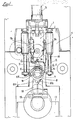
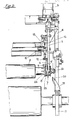
- the figures illustrate a fast coupling for the replacement of rollers, applied for example to a side supporting shoulder of a printing machines.
- two fast couplings positioned, respectively, on the opposite side shoulders, forming the supporting and guiding structures of the ends of the rollers.
- Each fast coupling substantially comprises a vertical slide (1), sliding vertically along the side tracks (2) and driven by an upper primary piston (3).
- the tracks (2) and piston (3) are substantially fixed to the supporting structure (4) of each side shoulder.
- each vertical slide (1) On the lower part of each vertical slide (1) are applied a fixed jaw (5) and a movable jaw (6), opposite, and forming a single seat in which is engaged the collar (7) of the idle bushes (8), installed at the ends of the interchangeable rollers (9).
- the seat of engagement formed by the opposite jaws (5) and (6), has substantially a circular form, open at the bottom, which is coupled to the diameter of each collar (7), winding it round the entire upper semicircumference and on two adjoining opposite zones which exceed the horizontal diameter from two sides and partially extend along the lower semicircumference.
- Said opposite zones (10) form the round opposite sectors of the lower semicircumference of siad seat of engagement, which serve, during lifting operations, to seize and support the idle bushes (8), on which weigh the corresponding interchangeable rollers (9).
- the lower opening of the seat being smaller than the diameter of the collar (7), of the idle bush (8) seized, guarantees the grip of the latter, in the closing and lifting phases, and improves detachment and discharge of the rollers, in the opening phases.
- Each movable jaw (6) is substantially formed by a shaped lever, supported on a pin (11) and equipped with a coupling (12), opposite its round sector (10), connected to the rod of a secondary piston (13).
- each movable jaw (6) comprises a tie (14) to which is connected one end of a safety return coil spring (15), fixed, at the other end, to an adjustable stop (16) applied to the same slide (1).
- a safety return coil spring 15
- an adjustable stop 16
- the upper pistons (3) control the slide (1) in downstroke.
- the downstroke of the slides (1) ends when the upper semicircumferences of the abovementioned seats reach the top surface of the collars (7) of the underlying idle bushes (8), present at the ends of a roller (9).
- the vertical slides (1) are capable of making an oscillation to consent the round sectors (10) of the fixed jaws (5), projecting, to easily exceed the diameter of the collars (7) of the idle bushes (8) and to grip one another, subsequently, on their lower semicircumference.
- the rods of the secondary pistons (13) are recalled and the movable jaws (6) close, engaging with the idle bushes (8).
- Lifting is obtained by driving in opposite direction the upper primary pistons (3); the vertical slides (1) slide upwards along the tracks (2) and everything is lifted.
- the side supporting structures (4), and at the bases (17) are positioned tippable brackets (18), supported on pins (19).
- brackets (18) After the lifting of an interchangeable roller (19), the abovementioned brackets (18), normally tipped laterally so as not to disturb the movement of the machines during operating phases, are rotated upwards and positioned in alignment with the roller lifted.
- the seatings (20) present the bottom (22) inclined; this serves to facilitate, at opening of the movable jaws (6), a slight rolling of the roller (9) towards the lower part of said bottoms (22) and a displacement of same sufficient to facilitate extraction of the fixed jaws (5).
- the idle bushes (8) are preferably, but not bindingly, installed on roller bearings (23), keyed on the ends (24) of the rollers (9), forming the supports on which the collars (21) are fixed.
- Safety means (25) are provided in compliance with anti-accident regulations.
Landscapes
- Engineering & Computer Science (AREA)
- Mechanical Engineering (AREA)
- Inking, Control Or Cleaning Of Printing Machines (AREA)
- Spinning Or Twisting Of Yarns (AREA)
- Rolls And Other Rotary Bodies (AREA)
Applications Claiming Priority (2)
| Application Number | Priority Date | Filing Date | Title |
|---|---|---|---|
| IT8821515A IT1226463B (it) | 1988-07-27 | 1988-07-27 | Aggancio rapido per la sostituzione di rulli |
| IT2151588 | 1988-07-27 |
Publications (2)
| Publication Number | Publication Date |
|---|---|
| EP0352364A2 true EP0352364A2 (fr) | 1990-01-31 |
| EP0352364A3 EP0352364A3 (fr) | 1991-01-09 |
Family
ID=11182953
Family Applications (1)
| Application Number | Title | Priority Date | Filing Date |
|---|---|---|---|
| EP19880117875 Withdrawn EP0352364A3 (fr) | 1988-07-27 | 1988-10-27 | Accouplément rapide pour remplacer des rouleaux |
Country Status (3)
| Country | Link |
|---|---|
| US (1) | US5022251A (fr) |
| EP (1) | EP0352364A3 (fr) |
| IT (1) | IT1226463B (fr) |
Cited By (4)
| Publication number | Priority date | Publication date | Assignee | Title |
|---|---|---|---|---|
| EP0467317A1 (fr) * | 1990-07-20 | 1992-01-22 | OFFICINE MECCANICHE GIOVANNI CERUTTI S.p.A. | Presse rotative pour impression avec cylindre d'impression échangeable |
| EP0586881A3 (fr) * | 1992-08-13 | 1994-03-30 | MAN Roland Druckmaschinen AG | Machine à imprimer rotative pour bandes en particulier des bandes en papier épaisses |
| EP0911158A3 (fr) * | 1997-10-21 | 1999-11-03 | Valmet Rotomec s.p.a. | Dispositif pour maintenir et enlever un cylindre d'impression rotatif sur des supports |
| WO2005092616A1 (fr) * | 2004-03-25 | 2005-10-06 | Windmöller & Hölscher Kg | Groupe d'impression de machine a imprimer, muni d'un rouleau presseur |
Families Citing this family (4)
| Publication number | Priority date | Publication date | Assignee | Title |
|---|---|---|---|---|
| US5241905A (en) * | 1992-10-27 | 1993-09-07 | Heidelberg Harris Inc. | Printing unit with releasable bearing clamp |
| DE19511710C1 (de) * | 1995-03-30 | 1996-04-11 | Roland Man Druckmasch | Einseitig offene Lagerung für rotationssymmetrische Bauteile, vorzugsweise für Walzenzapfen in Druckmaschinen |
| US5806427A (en) * | 1997-08-29 | 1998-09-15 | Goss Graphic Systems, Inc. | Printing press having carriage mounted interchangeable plate cylinders |
| ITMI20042038A1 (it) * | 2004-10-26 | 2005-01-26 | Paper Converting Machine Co | Gruppo goffratore per materiale in foglio |
Family Cites Families (11)
| Publication number | Priority date | Publication date | Assignee | Title |
|---|---|---|---|---|
| US2460504A (en) * | 1944-10-24 | 1949-02-01 | William C Huebner | Printing apparatus |
| DE1130451B (de) * | 1959-08-13 | 1962-05-30 | Miehle Goss Dexter Inc | Hilfsvorrichtung beim Auswechseln des Formzylinders von Rotationsdruck-maschinen |
| US3131631A (en) * | 1962-01-08 | 1964-05-05 | Inta Roto Machine Company Inc | Impression roll support and control means |
| US3529545A (en) * | 1967-11-21 | 1970-09-22 | Pannier Corp The | Rotary printer with printing cylinder drive wheels |
| US3625145A (en) * | 1969-06-05 | 1971-12-07 | Bobst Champlain Inc | Cylinder cart for exchanging cylinders on the fly |
| US3789757A (en) * | 1971-03-26 | 1974-02-05 | Motter J Printing Press Co | Printing press having automatic printing cylinder loading and unloading apparatus |
| DE2336791C3 (de) * | 1973-07-19 | 1978-12-21 | Maschinenfabrik Augsburg-Nuernberg Ag, 8900 Augsburg | Haltevorrichtung für die Lagerbuchsen eines Druckformzylinders einer Rotations-Tiefdruckmaschine |
| SE425773B (sv) * | 1979-05-07 | 1982-11-08 | Wifag Maschf | Anordning for utbyte av formcylindern i en djuptrycksrotationsmaskin |
| FR2485990A1 (fr) * | 1980-07-03 | 1982-01-08 | Holweg Const Mec | Dispositif pour le changement automatique de cylindres d'une imprimeuse flexographique |
| JPS58108144A (ja) * | 1981-12-23 | 1983-06-28 | Komori Printing Mach Co Ltd | 輪転印刷機の胴着脱装置 |
| IT1204804B (it) * | 1986-02-17 | 1989-03-10 | Cerutti Spa Off Mec | Unita' di stampa supplementare del tipo flessografiche |
-
1988
- 1988-07-27 IT IT8821515A patent/IT1226463B/it active
- 1988-10-27 EP EP19880117875 patent/EP0352364A3/fr not_active Withdrawn
-
1989
- 1989-11-02 US US07/430,807 patent/US5022251A/en not_active Expired - Fee Related
Cited By (5)
| Publication number | Priority date | Publication date | Assignee | Title |
|---|---|---|---|---|
| EP0467317A1 (fr) * | 1990-07-20 | 1992-01-22 | OFFICINE MECCANICHE GIOVANNI CERUTTI S.p.A. | Presse rotative pour impression avec cylindre d'impression échangeable |
| EP0586881A3 (fr) * | 1992-08-13 | 1994-03-30 | MAN Roland Druckmaschinen AG | Machine à imprimer rotative pour bandes en particulier des bandes en papier épaisses |
| US5351616A (en) * | 1992-08-13 | 1994-10-04 | Man Roland Druckmaschinen Ag | Rotary web printing machine, particularly for printing on thick or carton-type stock webs with replaceable plate cylinders |
| EP0911158A3 (fr) * | 1997-10-21 | 1999-11-03 | Valmet Rotomec s.p.a. | Dispositif pour maintenir et enlever un cylindre d'impression rotatif sur des supports |
| WO2005092616A1 (fr) * | 2004-03-25 | 2005-10-06 | Windmöller & Hölscher Kg | Groupe d'impression de machine a imprimer, muni d'un rouleau presseur |
Also Published As
| Publication number | Publication date |
|---|---|
| US5022251A (en) | 1991-06-11 |
| IT8821515A0 (it) | 1988-07-27 |
| IT1226463B (it) | 1991-01-16 |
| EP0352364A3 (fr) | 1991-01-09 |
Similar Documents
| Publication | Publication Date | Title |
|---|---|---|
| US8607538B2 (en) | Apparatus for changing film reels | |
| JP4163507B2 (ja) | 金属シート積重体を溶融炉へ供給する方法および装置 | |
| US3891204A (en) | Transfer mechanism for sheet material | |
| JPS6331798Y2 (fr) | ||
| US5022251A (en) | Fast coupling for roller replacement | |
| US6789659B2 (en) | Stator winding system and method with pallet on pallet arrangement | |
| CN107720243A (zh) | 纸卷输送装置 | |
| AU2009201532A1 (en) | Clamping Device for Lifting Slab, Panel or Sheet Material | |
| US2298006A (en) | Molding apparatus | |
| US1958133A (en) | Sheet phier | |
| JPH07328884A (ja) | 板状物加工機械において板状物に作用するグリッパの把持作動制御装置 | |
| KR101793506B1 (ko) | 지게차용 클램프 장치 | |
| EP1855820B1 (fr) | Appareil de cintrage pour des sections metalliques en forme de barres | |
| JPH07136728A (ja) | プレス機への材料供給処理装置 | |
| JPH06321485A (ja) | コンクリート製品の吊り上げ寄せ集め装置 | |
| US6021725A (en) | Apparatus for temporarily storing products, particularly at the exit of a quilting machine | |
| EP0907754B1 (fr) | Systeme de manutention d'articles sensiblement plats et souples, notamment des peaux | |
| US2921663A (en) | Sheet handling apparatus | |
| US4012938A (en) | Device for inserting or removing a hot blank in a drop hammer | |
| JPH0551582U (ja) | ロボットハンド | |
| JPH0333407Y2 (fr) | ||
| SU1080917A1 (ru) | Устройство дл установки изложниц на поддон дл сифонной разливки стали | |
| US3640335A (en) | Plant for closure of foundry molds | |
| JP2585474Y2 (ja) | 板材搬出装置 | |
| KR200260908Y1 (ko) | 슬라브 인출장치 |
Legal Events
| Date | Code | Title | Description |
|---|---|---|---|
| PUAI | Public reference made under article 153(3) epc to a published international application that has entered the european phase |
Free format text: ORIGINAL CODE: 0009012 |
|
| AK | Designated contracting states |
Kind code of ref document: A2 Designated state(s): AT BE CH DE ES FR GB LI NL SE |
|
| PUAL | Search report despatched |
Free format text: ORIGINAL CODE: 0009013 |
|
| AK | Designated contracting states |
Kind code of ref document: A3 Designated state(s): AT BE CH DE ES FR GB LI NL SE |
|
| STAA | Information on the status of an ep patent application or granted ep patent |
Free format text: STATUS: THE APPLICATION IS DEEMED TO BE WITHDRAWN |
|
| 18D | Application deemed to be withdrawn |
Effective date: 19910711 |