EP0352368A2 - Fermeture pour appareil de laboratoire - Google Patents
Fermeture pour appareil de laboratoire Download PDFInfo
- Publication number
- EP0352368A2 EP0352368A2 EP88121291A EP88121291A EP0352368A2 EP 0352368 A2 EP0352368 A2 EP 0352368A2 EP 88121291 A EP88121291 A EP 88121291A EP 88121291 A EP88121291 A EP 88121291A EP 0352368 A2 EP0352368 A2 EP 0352368A2
- Authority
- EP
- European Patent Office
- Prior art keywords
- locking
- opening
- closure
- securing
- locking element
- Prior art date
- Legal status (The legal status is an assumption and is not a legal conclusion. Google has not performed a legal analysis and makes no representation as to the accuracy of the status listed.)
- Withdrawn
Links
Images
Classifications
-
- E—FIXED CONSTRUCTIONS
- E05—LOCKS; KEYS; WINDOW OR DOOR FITTINGS; SAFES
- E05B—LOCKS; ACCESSORIES THEREFOR; HANDCUFFS
- E05B47/00—Operating or controlling locks or other fastening devices by electric or magnetic means
- E05B47/0001—Operating or controlling locks or other fastening devices by electric or magnetic means with electric actuators; Constructional features thereof
- E05B47/0002—Operating or controlling locks or other fastening devices by electric or magnetic means with electric actuators; Constructional features thereof with electromagnets
-
- B—PERFORMING OPERATIONS; TRANSPORTING
- B04—CENTRIFUGAL APPARATUS OR MACHINES FOR CARRYING-OUT PHYSICAL OR CHEMICAL PROCESSES
- B04B—CENTRIFUGES
- B04B7/00—Elements of centrifuges
- B04B7/02—Casings; Lids
- B04B7/06—Safety devices ; Regulating
-
- E—FIXED CONSTRUCTIONS
- E05—LOCKS; KEYS; WINDOW OR DOOR FITTINGS; SAFES
- E05B—LOCKS; ACCESSORIES THEREFOR; HANDCUFFS
- E05B47/00—Operating or controlling locks or other fastening devices by electric or magnetic means
- E05B47/06—Controlling mechanically-operated bolts by electro-magnetically-operated detents
- E05B47/0607—Controlling mechanically-operated bolts by electro-magnetically-operated detents the detent moving pivotally or rotatively
-
- E—FIXED CONSTRUCTIONS
- E05—LOCKS; KEYS; WINDOW OR DOOR FITTINGS; SAFES
- E05C—BOLTS OR FASTENING DEVICES FOR WINGS, SPECIALLY FOR DOORS OR WINDOWS
- E05C3/00—Fastening devices with bolts moving pivotally or rotatively
- E05C3/12—Fastening devices with bolts moving pivotally or rotatively with latching action
- E05C3/16—Fastening devices with bolts moving pivotally or rotatively with latching action with operating handle or equivalent member moving otherwise than rigidly with the latch
- E05C3/22—Fastening devices with bolts moving pivotally or rotatively with latching action with operating handle or equivalent member moving otherwise than rigidly with the latch the bolt being spring controlled
- E05C3/24—Fastening devices with bolts moving pivotally or rotatively with latching action with operating handle or equivalent member moving otherwise than rigidly with the latch the bolt being spring controlled in the form of a bifurcated member
-
- E—FIXED CONSTRUCTIONS
- E05—LOCKS; KEYS; WINDOW OR DOOR FITTINGS; SAFES
- E05B—LOCKS; ACCESSORIES THEREFOR; HANDCUFFS
- E05B47/00—Operating or controlling locks or other fastening devices by electric or magnetic means
- E05B47/0001—Operating or controlling locks or other fastening devices by electric or magnetic means with electric actuators; Constructional features thereof
- E05B47/0002—Operating or controlling locks or other fastening devices by electric or magnetic means with electric actuators; Constructional features thereof with electromagnets
- E05B47/0003—Operating or controlling locks or other fastening devices by electric or magnetic means with electric actuators; Constructional features thereof with electromagnets having a movable core
- E05B47/0004—Operating or controlling locks or other fastening devices by electric or magnetic means with electric actuators; Constructional features thereof with electromagnets having a movable core said core being linearly movable
-
- Y—GENERAL TAGGING OF NEW TECHNOLOGICAL DEVELOPMENTS; GENERAL TAGGING OF CROSS-SECTIONAL TECHNOLOGIES SPANNING OVER SEVERAL SECTIONS OF THE IPC; TECHNICAL SUBJECTS COVERED BY FORMER USPC CROSS-REFERENCE ART COLLECTIONS [XRACs] AND DIGESTS
- Y10—TECHNICAL SUBJECTS COVERED BY FORMER USPC
- Y10T—TECHNICAL SUBJECTS COVERED BY FORMER US CLASSIFICATION
- Y10T292/00—Closure fasteners
- Y10T292/08—Bolts
- Y10T292/1043—Swinging
- Y10T292/1044—Multiple head
- Y10T292/1045—Operating means
- Y10T292/1047—Closure
-
- Y—GENERAL TAGGING OF NEW TECHNOLOGICAL DEVELOPMENTS; GENERAL TAGGING OF CROSS-SECTIONAL TECHNOLOGIES SPANNING OVER SEVERAL SECTIONS OF THE IPC; TECHNICAL SUBJECTS COVERED BY FORMER USPC CROSS-REFERENCE ART COLLECTIONS [XRACs] AND DIGESTS
- Y10—TECHNICAL SUBJECTS COVERED BY FORMER USPC
- Y10T—TECHNICAL SUBJECTS COVERED BY FORMER US CLASSIFICATION
- Y10T292/00—Closure fasteners
- Y10T292/08—Bolts
- Y10T292/1043—Swinging
- Y10T292/1075—Operating means
- Y10T292/1082—Motor
Definitions
- the present invention relates to a tumbler for a laboratory device for locking a lid or a door and its housing with a hook in one and a lock in the other of the parts to be locked, the lock having a pivotable locking element with a claw-like opening that in the hook engages against the pressure of a spring and which can be released from engagement with the hook via an actuating element.
- Such a tumbler is used in particular to lock the lid of laboratory centrifuges.
- a laboratory centrifuge is known, for example, in the product information from Heraeus Sepatech GmbH, 3360 Osterode am Harz, "Suprafuge 22" (2M 8.87 / N Kr).
- This centrifuge has a housing with a lid on the top, which is hinged to two hinges.
- two hooks in the form of eyelets are rigidly fastened on the sides opposite the hinges, each of which engages in a corresponding lock, which is embedded and fastened in the housing.
- the object of the present invention is to provide a guard locking device for a laboratory device that meets high safety requirements and ensures secure locking during operation of the device, in particular under external vibrations or other stresses.
- a locking element which engages in the locking element under spring force and an opening element which is connected to the operating element and acts on the locking element are pivotably arranged between the locking element and the actuating element, and that a securing element engaging in the opening element and in the closing element is arranged pivotably under spring force against the opening element between them, wherein the pivot axes of the closure element, the locking element, the opening element and the securing element run parallel to one another, wherein the opening element has a guide surface for the securing element at one end, a locking lug at its other end, which engages behind a projection on the locking element in the locking position, wherein the securing element has a retaining lug in a central region of its guide surface, into which a cam of the opening element engages in the open position, wherein the locking element in the locking position has at its end opposite the opening element a first groove into which a first pin of the closing element, which delimits the claw-like opening on one side, engages, and wherein the
- the lock is constructed in such a way that the actuating element does not act directly on the closure element, but rather the movement of the actuating element is transmitted via two further elements, the opening element and the locking element. With the help of these two elements, in addition to the safety element, various safety functions can be installed.
- the securing element ensures that when the closure is opened, the locking element which bears against the opening element remains in an open position, since the cam arranged at the end of the opening element engages in the retaining lug of the securing element.
- the securing element is pivoted by the driver cam in such a way that the retaining lug releases the cam of the opening element, so that it is ensured that the locking element when closing the door or the lid and thus in the claw-like opening engaging hook again under the force of the spring acting on the locking element can pivot into the closed position, so that the first pin engages in the first groove of the locking element and thus locks the locking element.
- An additional security is achieved by the projection of the locking element, which comes into contact with the locking lug of the opening element in the locking position during forced pivoting under the influence of external forces in the direction of the opening position.
- the opening element can be actuated by an actuating element in the form of a lifting magnet which moves the opening element to open the lock.
- At least one switch with the movement of the locking element which immediately releases or locks the locking element in order to use this switch in a position in which the locking element releases the locking element, at least one operating function, for example the Circuit for the drive motor of a centrifuge to interrupt, so that an operation of the centrifuge is impossible with the lid open.
- the opening element bears against the actuating element under the force of a spring. It is hereby achieved that the piston of the lifting magnet is closed after the lock has been closed, i.e. after the hook is pushed back into the claw-like opening of the closure element, is pushed back into its starting position by the rotating locking element which presses on the opening element.
- An additional securing of the locking element in the locking position is achieved by a second groove on the locking element, into which a second pin of the locking element, which the claw-like opening on the other side, i. limited, engages on the side opposite the first pin.
- the locking element is secured at two points against forced opening.
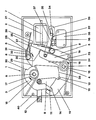
- the tumbler has a lock 1 with a housing 2, in which a closure element 3, a locking element 4, an opening element 5, a securing element 6 and an actuating element in the form of a lifting magnet 7 are arranged.
- the pivot axes 8 of the elements 3, 4, 5, 6 and 7 listed above run parallel to one another.
- the closure element 3 has a claw-like opening 9 which is delimited by a first pin 10 and a second pin 11.
- the bottom region of the claw-like opening 9 is adapted to a hook 12 which engages therein and is arranged, for example, on a door.
- the first pin 10 engages in a first groove 13 and the second pin 11 in a second groove 14 of the locking element 4.
- the locking element 4 is held in this locking position by a spring 15 which acts in the direction of arrow 16.
- a spring 17 acts on the closure element 3, which holds the closure element 3 under tension in the direction of the arrow 18, so that the pins 10 and 11 are held against the wall of the grooves 13 and 14.
- the locking element 4 has two legs 19 which extend approximately at an angle of 90 ° to one another, the outer leg 19 having the two grooves 13, 14 on its inner surface and the inner leg 19 with its end via a projection 20 on the opening element 5 is present.
- the opening element 5 is a rod-shaped part, the pivot axis 8 of which runs approximately in its center.
- the piston 21 of the lifting magnet 7 presses against the lower section of the opening element 5, as seen from the pivot axis 8, the opening element 5 being held in the locking position shown by a spring 22.
- the projection 24 is located approximately at the height of the pivot axis 8 of the locking element 4.
- the other, upper end of the opening element 5 is formed on the end face as a guide surface 25 with an additional, laterally outwardly directed cam 26.
- a driver cam 30 on the outside of the closure element 3 is assigned to the end opposite the guide surface 27 as seen from the pivot axis 8, which comes to rest against this end 29 in the open position and pivots the securing element 6.
- a spring 31 acts on the securing element 6, which rotates the blocking element 6 in the direction of the arrow 32 and holds its guide surface 27 against the guide surface 25 of the securing element 6.
- an actuating lever 33 On the leg 19 of the locking element 4, the end of which abuts the opening element 5, an actuating lever 33 is arranged in an articulated manner, which is guided at its other end via an elongated hole 34 on a pin 35. On this actuating lever 33 there is a switching cam 36 which actuates the switching arm 37 of a microswitch 38 in a position of the blocking element 4 pivoted into the open position.
- a microswitch 38 With this microswitch 38, circuits, for example the circuit of the drive motor of a centrifuge, can be interrupted in the open position.
- the lifting magnet 7 is actuated, the piston 21 of which pivots the opening element 5 until its cam 26 engages with the retaining lug 28 of the securing element 6.
- the locking lug 23 pivots at the other end of the opening element 5 from the engagement area of the projection 24 on the locking element 4.
- the locking element 4 is pivoted via the opening element 5, so that the pins 10 and 11 come out of engagement with the grooves 13 and 14.
- closure element 3 and the locking element 4 are guided to one another via the surface pairing 39 until the closure element 3, pivoted in the direction of arrow 18 by the spring 17, comes into contact with the outside of the second pin 11 on the stop 40 formed by a pin; in this position the hook 12 is released from the claw-like opening 9.
- the hook 12 In order to close the lid or the door with the hook 12, the hook 12 is inserted into the claw-like opening 9, which then comes to rest on the surface in the extension of the first pin 10 and the locking element 3 counter to that indicated by the arrow 18 Direction of rotation, ie counter to the force of the spring 17, pivots into its closed position.
- the closure element 3 and the spring element 4 are brought together via their surface pairing 39 until the first pin 10 and the second pin 11 snap into the associated first groove 13 and second groove 14.
- the blocking element 4 When the blocking element 4 is pivoted, the piston 21 of the lifting magnet 7 is pushed back into its starting position, which can be seen in the figure, via the opening element 5.
Landscapes
- Engineering & Computer Science (AREA)
- Mechanical Engineering (AREA)
- Physics & Mathematics (AREA)
- Electromagnetism (AREA)
- Centrifugal Separators (AREA)
- Clamps And Clips (AREA)
Applications Claiming Priority (2)
| Application Number | Priority Date | Filing Date | Title |
|---|---|---|---|
| DE3821840A DE3821840C1 (fr) | 1988-06-29 | 1988-06-29 | |
| DE3821840 | 1988-06-29 |
Publications (2)
| Publication Number | Publication Date |
|---|---|
| EP0352368A2 true EP0352368A2 (fr) | 1990-01-31 |
| EP0352368A3 EP0352368A3 (fr) | 1990-10-10 |
Family
ID=6357462
Family Applications (1)
| Application Number | Title | Priority Date | Filing Date |
|---|---|---|---|
| EP19880121291 Withdrawn EP0352368A3 (fr) | 1988-06-29 | 1988-12-20 | Fermeture pour appareil de laboratoire |
Country Status (3)
| Country | Link |
|---|---|
| US (1) | US4978153A (fr) |
| EP (1) | EP0352368A3 (fr) |
| DE (1) | DE3821840C1 (fr) |
Families Citing this family (58)
| Publication number | Priority date | Publication date | Assignee | Title |
|---|---|---|---|---|
| DE4015522A1 (de) * | 1989-09-14 | 1991-03-28 | Bosch Gmbh Robert | Vorrichtung zum sperren und entsperren von geschlossenen tueren zum innenraum eines kraftfahrzeuges |
| DE4025134C1 (fr) * | 1990-08-08 | 1991-11-14 | Eppendorf - Netheler - Hinz Gmbh, 2000 Hamburg, De | |
| DE4037637A1 (de) * | 1990-11-27 | 1992-06-04 | Kiekert Gmbh Co Kg | Kraftfahrzeugtuerverschluss mit schlosskasten, drehfalle, sperrklinke und ausloesehebel sowie speichereinrichtung fuer den ausloesehebel |
| GB9108447D0 (en) * | 1991-04-19 | 1991-06-05 | Rockwell Automotive Body Syst | Vehicle door latches |
| GB9915432D0 (en) * | 1999-07-01 | 1999-09-01 | Meritor Light Vehicle Sys Ltd | Latch assembly |
| US5570915A (en) * | 1993-11-30 | 1996-11-05 | Adams Rite Sabre International | Flush-mounted door latch |
| JP2739677B2 (ja) * | 1993-12-13 | 1998-04-15 | 三井金属鉱業株式会社 | 車両用扉のロック装置 |
| US5492382A (en) * | 1994-05-27 | 1996-02-20 | Security & Control Equipment, Inc. | Electro-mechanical locks for security accesses |
| US5535607A (en) * | 1994-06-08 | 1996-07-16 | General Motors Corporation | Door latch with integral switch |
| JP3121744B2 (ja) * | 1995-06-01 | 2001-01-09 | 三井金属鉱業株式会社 | 車両ドアロック装置におけるフルラッチ検出スイッチ |
| EP0808977B1 (fr) * | 1996-05-21 | 2000-08-16 | Robert Bosch Gmbh | Méthode pour le contrôle d'une serrure pour portière de véhicule automobile actionnée de façon électrique |
| DE19629361C1 (de) * | 1996-07-20 | 1997-11-20 | Heraeus Instr Gmbh | Schloß |
| JP3430436B2 (ja) * | 1997-03-28 | 2003-07-28 | 株式会社大井製作所 | 自動車用ドアロック装置 |
| JP3821411B2 (ja) * | 1997-10-14 | 2006-09-13 | 株式会社大井製作所 | 自動車用ロックの検知スイッチ |
| US6027148A (en) * | 1998-06-12 | 2000-02-22 | Shoemaker; Rodney | Security device for a movable closure and method therefor |
| US6089626A (en) * | 1998-06-12 | 2000-07-18 | Shoemaker; Rodney | Security device for a movable closure and method therefor |
| US6139073A (en) * | 1998-08-31 | 2000-10-31 | Westinghouse Air Brake Company | Lock assembly |
| DE19902561C5 (de) * | 1999-01-22 | 2009-02-19 | Witte-Velbert Gmbh & Co. Kg | Verschluß mit Sperrklinke und Drehfalle |
| GB0018102D0 (en) * | 2000-07-25 | 2000-09-13 | Meritor Light Vehicle Sys Ltd | An actuator |
| US20030000149A1 (en) * | 2001-02-23 | 2003-01-02 | Oakley Robert L. | Linearly actuated locking device for transit vehicle door system |
| CA2469258C (fr) * | 2001-12-12 | 2010-11-16 | Intier Automotive Closures Inc. | Levier de charge avec a levier de cliquet en deux parties |
| US6886869B2 (en) * | 2001-12-14 | 2005-05-03 | Richard A. Martinez | Electromechanical locking mechanism |
| US6834464B2 (en) | 2002-04-09 | 2004-12-28 | Rodney T. Shoemaker | Overhead door lock system and control unit therefor |
| JP4359673B2 (ja) * | 2002-11-22 | 2009-11-04 | 旭精工株式会社 | ディスクの案内装置 |
| DE10312304B4 (de) * | 2003-03-20 | 2005-12-29 | Brose Schließsysteme GmbH & Co.KG | Kraftffahrzeugschloß |
| US20040212197A1 (en) * | 2003-04-22 | 2004-10-28 | Rodney Shoemaker | Overhead door locking apparatus and method of operation |
| JP4239785B2 (ja) * | 2003-10-21 | 2009-03-18 | 三菱自動車工業株式会社 | 車両用扉部材オープナー装置 |
| US20050134052A1 (en) * | 2003-12-23 | 2005-06-23 | Honeywell International Inc. | Pulsed electromagnetic application in vehicle door latch |
| GB2409705B (en) * | 2003-12-31 | 2006-09-27 | Honeywell Int Inc | Latch mechanism with environmentally protected portion |
| GB2409706B (en) * | 2003-12-31 | 2006-11-08 | Honeywell Int Inc | Low release energy latch mechanism |
| US7878560B1 (en) * | 2004-09-20 | 2011-02-01 | Hanchett Entry Systems | Electromechanical locking device intended for remote access control |
| RU2398948C2 (ru) * | 2005-02-18 | 2010-09-10 | Меритор Текнолоджи, Инк. | Защелка |
| US7461872B2 (en) * | 2006-04-12 | 2008-12-09 | Computerized Security Systems, Inc. | Motorized swing bolt lock |
| US8047582B1 (en) * | 2006-12-23 | 2011-11-01 | Securitron Magnalock Corporation | Electro-mechanical lock |
| FR2922933B1 (fr) * | 2007-10-26 | 2012-10-19 | Fermetures Groom | Dispositif de verrouillage d'elements ouvrants et fenetre comprenant un tel dispositif. |
| AT505923B1 (de) * | 2007-12-21 | 2009-05-15 | Knorr Bremse Gmbh | Verriegelungsvorrichtung einer tür |
| EP2424404B1 (fr) * | 2009-04-27 | 2016-09-21 | Accuride International Inc. | Mécanisme de coulissement et de verrouillage de tiroir |
| US8424934B2 (en) * | 2010-01-27 | 2013-04-23 | Tim Askins | Electromechanical door locks for lifts |
| DE102011012370A1 (de) * | 2010-02-24 | 2011-08-25 | Magna Closures S.P.A. | Fahrzeugschloss mit Sperrklinke mit einzelner Kerbe |
| US9777512B2 (en) | 2011-04-14 | 2017-10-03 | Janus International Group, Llc | Locking apparatus for a rollup door or other movable object |
| US8789859B2 (en) * | 2011-04-14 | 2014-07-29 | Janus International Group, Llc | Electronic lock for a rollup door |
| JP5437309B2 (ja) * | 2011-04-22 | 2014-03-12 | アイシン精機株式会社 | 回転レバーの位置保持装置および該回転レバーの位置保持装置を備える車両用ドアロック装置 |
| DE102012102723A1 (de) * | 2011-09-23 | 2013-03-28 | Huf Hülsbeck & Fürst Gmbh & Co. Kg | Kraftfahrzeugtürverschluss |
| US10563681B2 (en) * | 2011-12-21 | 2020-02-18 | Deka Products Limited Partnership | System, method, and apparatus for clamping |
| DE112013003208T5 (de) * | 2012-06-25 | 2015-04-02 | Magna Closures Inc. | Fahrzeugschloss mit unmittelbarer Verriegelung der Sperrklinke |
| JP6219943B2 (ja) | 2012-07-18 | 2017-10-25 | アキュライド インターナショナル, インコーポレイテッドAccuride International, Inc. | 引き出しスライド及び電気的に作動されるロッキング機構 |
| FR3005274B1 (fr) * | 2013-05-02 | 2015-05-01 | Afi Centrifuge | Centrifugeuse de laboratoire munie de moyens pour le verrouillage d'un couvercle dans sa position fermee |
| DE102013209084A1 (de) * | 2013-05-16 | 2014-11-20 | Kiekert Ag | Kraftfahrzeugtürverschluss mit verhinderter Scheinschließung |
| US10577842B2 (en) * | 2013-11-22 | 2020-03-03 | Gecom Corporation | Vehicle hood latches |
| US9657502B2 (en) | 2014-02-12 | 2017-05-23 | Hyundai Translead | Door latch activator for trailers or truck bodies |
| CN105624977A (zh) * | 2014-11-25 | 2016-06-01 | 伊利诺斯工具制品有限公司 | 门锁及上盖式洗衣机 |
| US11208015B2 (en) * | 2015-03-12 | 2021-12-28 | Kiekert Ag | Motor vehicle door lock, particularly a backrest lock on a motor vehicle seat |
| JP6872561B2 (ja) * | 2016-12-28 | 2021-05-19 | エッペンドルフ・ハイマック・テクノロジーズ株式会社 | 遠心機 |
| WO2019153222A1 (fr) * | 2018-02-09 | 2019-08-15 | 厦门美科安防科技有限公司 | Armoire de stockage partagée et serrure associée |
| US11421455B2 (en) * | 2018-10-03 | 2022-08-23 | Inteva Products, Llc | Hood latch for motor vehicle having under hood storage |
| US10914098B2 (en) * | 2019-05-30 | 2021-02-09 | Digilock Asia Ltd. | Enclosure latch system |
| US10988959B1 (en) * | 2020-06-17 | 2021-04-27 | Camden Marketing Inc | Rim strike assembly and methods of use |
| WO2025180689A1 (fr) * | 2024-02-27 | 2025-09-04 | Ika - Werke Gmbh & Co. Kg | Centrifugeuse |
Family Cites Families (7)
| Publication number | Priority date | Publication date | Assignee | Title |
|---|---|---|---|---|
| DE1127746B (de) * | 1960-10-19 | 1962-04-12 | Daimler Benz Ag | Verschluss fuer Deckel, Tueren usw., insbesondere fuer Kraftfahrzeugtueren |
| US3504511A (en) * | 1968-03-04 | 1970-04-07 | Perry E Allen | Electric lock release |
| IT1115555B (it) * | 1977-09-12 | 1986-02-03 | Mecanismes Comp Ind De | Serratura particolarmente per porte di autoveicoli |
| DE2816395A1 (de) * | 1978-04-15 | 1979-10-25 | Heraeus Christ Gmbh | Zentrifuge mit deckelzuhaltung |
| DD154255A3 (de) * | 1980-08-29 | 1982-03-10 | Lothar Pomper | Deckelverschlusseinrichtung fuer schutzkessel von zentrifugen |
| US4756563A (en) * | 1986-08-11 | 1988-07-12 | General Motors Corporation | Vehicle door latch |
| FR2607546B1 (fr) * | 1986-12-02 | 1989-03-10 | Rockwell Cim | Serrure, notamment pour porte de vehicule automobile |
-
1988
- 1988-06-29 DE DE3821840A patent/DE3821840C1/de not_active Expired
- 1988-12-20 EP EP19880121291 patent/EP0352368A3/fr not_active Withdrawn
-
1989
- 1989-06-29 US US07/373,944 patent/US4978153A/en not_active Expired - Lifetime
Also Published As
| Publication number | Publication date |
|---|---|
| DE3821840C1 (fr) | 1989-10-19 |
| US4978153A (en) | 1990-12-18 |
| EP0352368A3 (fr) | 1990-10-10 |
Similar Documents
| Publication | Publication Date | Title |
|---|---|---|
| DE3821840C1 (fr) | ||
| DE69224017T2 (de) | Verriegelbarer Bedienungsdrehgriff für Schalter | |
| DE69414624T2 (de) | Zylinderschloss-Schlüssel-Kombination | |
| DE69012804T2 (de) | Elektrisch arbeitende sicherungsplatte für türschlösser. | |
| EP0878017B1 (fr) | Dispositif d'actionnement verrouillable pour commutateur rotatif | |
| DE3617321C2 (fr) | ||
| DE10152617A1 (de) | Fahrzeugtürschloss | |
| DE69207320T2 (de) | Verbesserter Schloss mit einer Einrichtung zwecks Öffnen im Notfall | |
| DE69200690T2 (de) | Anlage um einen Mikrowellenofen in eine Startbereitschaftsstellung zu bringen. | |
| DE2838175C2 (de) | Verschluß für eine Geschirrspülmaschine | |
| DE68915149T2 (de) | Türverschlusseinrichtung. | |
| DE19643370A1 (de) | Einschnappklinke mit einem Knebel mit obenliegendem Drehpunkt und einem eingebauten Schalter | |
| DE68911882T2 (de) | Funktionelles Verriegelungsgehäuse für Mittelspannungs-Schaltanlage. | |
| DE69713130T2 (de) | Unterer Haken für Dreipunktgestänge | |
| DE3040586C2 (de) | Aufsetzschloß mit einer Schubfalle | |
| DE4407912C2 (de) | Elektromechanisches Schloß | |
| DE69123128T2 (de) | Einrichtung für die Bedienung eines Fahrzeugschlosses | |
| CH620494A5 (en) | Locking device | |
| AT394241B (de) | Schloss | |
| EP0654556A1 (fr) | Dispositif de fermeture | |
| CH671603A5 (fr) | ||
| DE4041877C2 (de) | Türschloß für ein Kraftfahrzeug | |
| DE8326565U1 (de) | Hebevorrichtung | |
| CH277919A (de) | Schloss. | |
| EP0414165A1 (fr) | Serrure à permutation pour malles, sacs ou similaires |
Legal Events
| Date | Code | Title | Description |
|---|---|---|---|
| PUAI | Public reference made under article 153(3) epc to a published international application that has entered the european phase |
Free format text: ORIGINAL CODE: 0009012 |
|
| 17P | Request for examination filed |
Effective date: 19890112 |
|
| AK | Designated contracting states |
Kind code of ref document: A2 Designated state(s): BE CH DE ES FR GB GR IT LI LU NL SE |
|
| PUAL | Search report despatched |
Free format text: ORIGINAL CODE: 0009013 |
|
| AK | Designated contracting states |
Kind code of ref document: A3 Designated state(s): BE CH DE ES FR GB GR IT LI LU NL SE |
|
| 17Q | First examination report despatched |
Effective date: 19920604 |
|
| STAA | Information on the status of an ep patent application or granted ep patent |
Free format text: STATUS: THE APPLICATION IS DEEMED TO BE WITHDRAWN |
|
| 18D | Application deemed to be withdrawn |
Effective date: 19921015 |