EP0352380A1 - Lenkrolle - Google Patents
Lenkrolle Download PDFInfo
- Publication number
- EP0352380A1 EP0352380A1 EP88306899A EP88306899A EP0352380A1 EP 0352380 A1 EP0352380 A1 EP 0352380A1 EP 88306899 A EP88306899 A EP 88306899A EP 88306899 A EP88306899 A EP 88306899A EP 0352380 A1 EP0352380 A1 EP 0352380A1
- Authority
- EP
- European Patent Office
- Prior art keywords
- arm
- relative
- attachment member
- interfering
- wheel
- Prior art date
- Legal status (The legal status is an assumption and is not a legal conclusion. Google has not performed a legal analysis and makes no representation as to the accuracy of the status listed.)
- Granted
Links
Images
Classifications
-
- B—PERFORMING OPERATIONS; TRANSPORTING
- B60—VEHICLES IN GENERAL
- B60B—VEHICLE WHEELS; CASTORS; AXLES FOR WHEELS OR CASTORS; INCREASING WHEEL ADHESION
- B60B33/00—Castors in general ; Anti-clogging castors
- B60B33/0078—Castors in general ; Anti-clogging castors characterised by details of the wheel braking mechanism
-
- B—PERFORMING OPERATIONS; TRANSPORTING
- B60—VEHICLES IN GENERAL
- B60B—VEHICLE WHEELS; CASTORS; AXLES FOR WHEELS OR CASTORS; INCREASING WHEEL ADHESION
- B60B33/00—Castors in general ; Anti-clogging castors
- B60B33/02—Castors in general ; Anti-clogging castors with disengageable swivel action, i.e. comprising a swivel locking mechanism
- B60B33/021—Castors in general ; Anti-clogging castors with disengageable swivel action, i.e. comprising a swivel locking mechanism combined with braking of castor wheel
Definitions
- the present invention relates to a castor comprising a body, a wheel mounted for rotation relative to the body about a rolling axis, an attachment member connected with the body for swiveling relative thereto about a swivel axis which is transverse to and is offset from the rolling axis and braking means for braking rotation of the wheel and swivelling of the body relative to the attachment member.
- the braking means comprises a brake element which lies at least partly in the gap and actuating means for moving the brake element along a path which extends transversely of both the swivelling axis and the rolling axis.
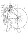
- the castor comprises a wheel 10 mounted for rotation about a rolling axis 11 on a body 12.
- the body comprises an upper portion 13 and a pair of spaced limbs, one only of which is shown at 14, extending downwardly from the upper portion at opposite sides of the wheel.
- the limbs carry an axle provided with bearings for supporting the wheel.
- the general arrangement of the body, wheel, axle and bearings may be a known arrangement.
- the castor further comprises an attachment member 16 which, in use, is fixed with respect to a container or other article to be provided with castors.
- the attachment member comprises an upper element 17 of plate like form defining near to its periphery apertures to receive bolts or other fasteners, by means of which the castor can be secured to the article.
- the attachment member further comprises a lower element 18 which is circular, has a diameter considerably less than the corresponding dimension of the upper element 17 and is secured to the upper element by means of a rivet 19.
- the lower element 18 extends through an aperture defined by the upper portion 13 of the body and overlaps with the body at the underside of the upper portion 13, so that the body is trapped between the elements 17 and 18.
- a first set of bearing elements is interposed between the body and the upper element 17 and a second set of bearing elements is interposed between the body and the lower element 18.
- the body 12 is thereby connected with the attachment member 16 for swivelling relative thereto about a swivel axis 20 which is offset from and is perpendicular to the rolling axis 11.
- a brake element 22 is arranged to lie at least partly in this gap and is supported for movement relative to the body 12 along a path which extends along the gap 21 in a direction transverse to both the swivelling axis 20 and the rolling axis 11.
- This path may be rectilinear or curved.
- the path of movement of the brake element 22 is an arc of a circle centered on the rolling axis 11.
- the brake element 22 is wedge-shaped, having an upper surface 23 which faces towards the attachment member 16 and a lower surface 24 which faces towards the wheel 10 and is convergent with the surface 23. As shown in Figure 1, when the brake element is at one end of its path of travel, there is a clearance space between the surface 24 and the wheel and the upper surface 23 is spaced considerably from the attachment member 16.
- the brake element 22 is carried by an arm 25 connected with the body 12 for pivoting relative thereto.
- the pivot axis of the arm 25 coincides with the rolling axis 11.
- the pivot axis of the arm may be spaced from and parallel to the rolling axis.
- a first portion of the arm 25 extends from its pivot axis in one direction and carries the brake element.
- a second portion of the arm extends from the pivot axis in the opposite direction and is connected by a linkage 26 with the body 12.
- the linkage 26 is a toggle linkage and comprises a first element 27 pivotally connected with the body and with a second element 28 of the linkage which is pivotally connected with the arm 25.
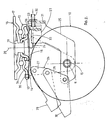
- the pivotal connection between the elements 27 and 28 can be moved from a position at one side of a rectilinear line joining the axis of the pivotal connection between the body and the element 27 with the axis of the pivotal connection between the arm and the element 28 to a position at the opposite side of that line, such movement of the toggle linkage causing the arm to pivot in an anti-clockwise direction, as viewed in the drawings.
- the elements 27 and 28 are provided with respective abutments which engage each other when the elements are in the position illustrated in Figure 2, to limit pivoting of the arm 25.
- the element 27 is provided with a foot pedal 29 which can be depressed when the linkage 26 is in the position shown in Figure 1 to set the linkage in the position of Figure 2.
- the element 28 include a foot pedal 30 which can be depressed to return the linkage from the position illustrated in Figure 2 to the position of Figure 1.
- the elements 27 and 28 and the arm 25 each preferably comprises a pair of limbs disposed at opposite sides of the wheel 10.
- the pedals 29 and 30 extend between the limbs of the elements 27 and 28 respectively and the brake element 22 lies between the limbs of the arm 25.
- the limbs of the arm 25 are connected to each other adjacent to the brake element 22 by a web 31.
- Adjustment means is provided for adjusting the position of the brake element relative to this web.
- the adjustment means comprises a screw and nut mechanism, the screw 32 of which can be turned to move the brake element towards and away from the web 3l and so vary the distance between the brake element 22 and the swivel axis 20, when the linkage 26 is in the position shown in Figure 1.
- the position of the brake element may be adjusted initially to compensate for manufacturing tolerances and during the service life of the castor to compensate for wear of components of the castor.
- the brake element is further connected with the arm 25 by a resilient element 33 which, in the example illustrated, is a leaf spring.
- the leaf spring biases the brake element to the position shown in Figure 1 but can flex to permit limited movement of the brake element relative to the arm 25 towards and away from the attachment member 16.
- the leaf spring ensures that the brake element remains clear of the wheel 10 when the linkage 26 is in the position of Figure 1.
- the castor further comprises an interfering element 34 which is connected with the body 12 for swivelling with the body relative to the attachment member 16.
- the interfering element lies generally below the attachment member, above the wheel and between the limbs of the body 12.
- An end portion of the interfering element is fixed by rivets 35 to the upper portion 13 of the body at a position remote from the swivel axis 20.
- the interfering element extends from the rivets 35 around the swivel axis to overlap the entire lower element 18, as viewed along the swivel axis.
- An annular row of teeth 36 is formed on the lower element 18, these teeth being presented towards the interfering element.
- An arcuate row of complimentary teeth 37 is formed on the interfering element and presented upwardly for cooperation with the teeth 36.
- the row of teeth 37 is movable into and out of engagement with corresponding ones of the teeth 36 by flexing of the interfering element 34.
- this element is formed as a leaf-spring and may be formed of spring steel.
- the teeth 37 are spaced downwardly from the teeth 36.
- a portion of the interfering element which is not formed with teeth may engage the lower element 18 at a position between the rivets 35 and the teeth 37.
- the brake element 22 is moved further into the gap 21 by movement of the linkage 26 into the position of Figure 2, the upper surface 23 of the brake element bears against the interfering element 34 and causes flexing of the interfering element until the teeth 37 are enmeshed with teeth 36. Further flexing of the interfering element is then prevented by the attachment member 16.
- the leaf spring 33 then flexs to permit pivoting of the arm 25 towards the attachment number 16 whilst the brake element 22 is deflected from its arcuate path to move in a direction perpendicular to the swivel axis 20.
- Such movement increases the pressure under which the brake element engages the wheel 10.
- the lower surface 24 of the brake element will engage the peripheral surface of the wheel before the teeth 37 are fully enmeshed with the teeth 36.
- the peripheral surface of the wheel 10 is generally presented by a tyre capable of deforming under pressure.
- the teeth 37 may be formed on the brake element 22 if the additional resistance to swivelling provided by the interfering element is not required.
- the interfering element may be omitted.
- linkage 26 may be substituted by an alternative linkage for pivoting the arm 25 relative to the body 12.
- Such linkage may, for example, have only a single foot pedal.
- the linkage may be adapted for remote operation.
- the castor has a single wheel. It will also be appreciated that a single tooth 37 may be provided on the interfering element 34. However, a row of such teeth is preferred to provide more reliable restraint of swivelling and to reduce the risk of damage being caused to the teeth.
Landscapes
- Engineering & Computer Science (AREA)
- Mechanical Engineering (AREA)
- Braking Arrangements (AREA)
Applications Claiming Priority (1)
| Application Number | Priority Date | Filing Date | Title |
|---|---|---|---|
| GB8701300A GB2200042B (en) | 1987-01-21 | 1987-01-21 | Castor |
Publications (3)
| Publication Number | Publication Date |
|---|---|
| EP0352380A1 true EP0352380A1 (de) | 1990-01-31 |
| EP0352380B1 EP0352380B1 (de) | 1993-03-31 |
| EP0352380B2 EP0352380B2 (de) | 1996-02-07 |
Family
ID=10610996
Family Applications (1)
| Application Number | Title | Priority Date | Filing Date |
|---|---|---|---|
| EP19880306899 Expired - Lifetime EP0352380B2 (de) | 1987-01-21 | 1988-07-27 | Lenkrolle |
Country Status (3)
| Country | Link |
|---|---|
| EP (1) | EP0352380B2 (de) |
| DE (1) | DE3879938T2 (de) |
| GB (1) | GB2200042B (de) |
Cited By (3)
| Publication number | Priority date | Publication date | Assignee | Title |
|---|---|---|---|---|
| EP0618089A1 (de) * | 1993-03-30 | 1994-10-05 | Guitel-Etienne Mobilor | Lenkrolle mit Richtungsverriegelung |
| EP0722849A1 (de) * | 1995-01-23 | 1996-07-24 | Guitel-Etienne Mobilor | Lenkrolle mit einstellbarer Richtungsverriegelung |
| EP0722848A1 (de) * | 1995-01-20 | 1996-07-24 | Guitel-Etienne Mobilor | Lenkrolle mit geschützter Richtungsverriegelung |
Families Citing this family (3)
| Publication number | Priority date | Publication date | Assignee | Title |
|---|---|---|---|---|
| GB2200042B (en) * | 1987-01-21 | 1991-05-29 | British Castors Ltd | Castor |
| GB2220560B (en) * | 1988-05-21 | 1991-10-16 | British Castors Ltd | Castor and method of braking and releasing a castor wheel |
| DE19510011A1 (de) * | 1995-03-23 | 1996-09-26 | Wicke Gmbh & Co | Lenkrolle für verfahrbare Arbeitsbühnen, Gerüste o. dgl. |
Citations (6)
| Publication number | Priority date | Publication date | Assignee | Title |
|---|---|---|---|---|
| US2900659A (en) * | 1957-03-20 | 1959-08-25 | Divine Brothers Company | Caster locking mechanism |
| DE1228768B (de) * | 1957-12-19 | 1966-11-17 | Romeca S A | Vorrichtung zur Sperrung der Schwenk- und Drehbewegung eines um einen lotrechten Zapfen eines Moebelstueckes schwenkbaren Rades |
| DE1580179A1 (de) * | 1967-01-07 | 1971-12-23 | Schulte & Co Kugelfab | Feststellvorrichtung fuer Lenkrollen |
| GB2047364A (en) * | 1979-03-26 | 1980-11-26 | Blickle Heinrich Gmbh Co Kg | Improvements in or relating to devices for arresting movement of castor wheels |
| US4349937A (en) * | 1980-07-11 | 1982-09-21 | Stewart-Warner Corporation | Caster assembly with swivel lock and brake |
| GB2200042A (en) * | 1987-01-21 | 1988-07-27 | British Castors Ltd | Castor |
Family Cites Families (7)
| Publication number | Priority date | Publication date | Assignee | Title |
|---|---|---|---|---|
| GB1052780A (de) * | ||||
| GB743438A (en) * | 1953-06-25 | 1956-01-18 | S B Whitfield & Company Ltd | Improvements in bedstead castors and brakes therefor |
| GB839272A (en) * | 1958-05-02 | 1960-06-29 | Flexello Castors & Wheels Ltd | Improvements in castors |
| DE1575681A1 (de) * | 1967-01-21 | 1972-02-24 | Tente Rollen Gmbh & Co | Laufrolle,insbesondere Lenkrolle,mit einer Feststellvorrichtung zur Blockierung der Laufbeweglichkeit und/oder Schwenkbeweglichkeit des Laufrades |
| US4077087A (en) * | 1976-12-10 | 1978-03-07 | Quick-Set, Incorporated | Caster and brake assembly |
| US4449268A (en) * | 1982-01-29 | 1984-05-22 | E. R. Wagner Mfg. Co. | Caster wheel brake having an overcenter latch |
| GB2147802B (en) * | 1983-10-13 | 1987-02-25 | Revvo Castor Co Ltd | Improvements in and relating to castors |
-
1987
- 1987-01-21 GB GB8701300A patent/GB2200042B/en not_active Expired - Lifetime
-
1988
- 1988-07-27 DE DE19883879938 patent/DE3879938T2/de not_active Expired - Fee Related
- 1988-07-27 EP EP19880306899 patent/EP0352380B2/de not_active Expired - Lifetime
Patent Citations (6)
| Publication number | Priority date | Publication date | Assignee | Title |
|---|---|---|---|---|
| US2900659A (en) * | 1957-03-20 | 1959-08-25 | Divine Brothers Company | Caster locking mechanism |
| DE1228768B (de) * | 1957-12-19 | 1966-11-17 | Romeca S A | Vorrichtung zur Sperrung der Schwenk- und Drehbewegung eines um einen lotrechten Zapfen eines Moebelstueckes schwenkbaren Rades |
| DE1580179A1 (de) * | 1967-01-07 | 1971-12-23 | Schulte & Co Kugelfab | Feststellvorrichtung fuer Lenkrollen |
| GB2047364A (en) * | 1979-03-26 | 1980-11-26 | Blickle Heinrich Gmbh Co Kg | Improvements in or relating to devices for arresting movement of castor wheels |
| US4349937A (en) * | 1980-07-11 | 1982-09-21 | Stewart-Warner Corporation | Caster assembly with swivel lock and brake |
| GB2200042A (en) * | 1987-01-21 | 1988-07-27 | British Castors Ltd | Castor |
Cited By (8)
| Publication number | Priority date | Publication date | Assignee | Title |
|---|---|---|---|---|
| EP0618089A1 (de) * | 1993-03-30 | 1994-10-05 | Guitel-Etienne Mobilor | Lenkrolle mit Richtungsverriegelung |
| FR2703300A1 (fr) * | 1993-03-30 | 1994-10-07 | Guitel Etienne Mobilor | Roulette pivotante à blocage directionnel. |
| US5450650A (en) * | 1993-03-30 | 1995-09-19 | Guitel-Etienne Mobilor | Pivoting castor with directional locking |
| AU674047B2 (en) * | 1993-03-30 | 1996-12-05 | Guitel-Etienne Mobilor | Pivoting castor with directional locking |
| EP0722848A1 (de) * | 1995-01-20 | 1996-07-24 | Guitel-Etienne Mobilor | Lenkrolle mit geschützter Richtungsverriegelung |
| FR2729614A1 (fr) * | 1995-01-20 | 1996-07-26 | Guitel Etienne Mobilor | Roulette pivotante a blocage directionnel protege |
| EP0722849A1 (de) * | 1995-01-23 | 1996-07-24 | Guitel-Etienne Mobilor | Lenkrolle mit einstellbarer Richtungsverriegelung |
| FR2729613A1 (fr) * | 1995-01-23 | 1996-07-26 | Guitel Etienne Mobilor | Roulette pivotante a blocage directionnel a couple reglable |
Also Published As
| Publication number | Publication date |
|---|---|
| DE3879938D1 (de) | 1993-05-06 |
| DE3879938T2 (de) | 1994-01-27 |
| GB8701300D0 (en) | 1987-02-25 |
| GB2200042A (en) | 1988-07-27 |
| GB2200042B (en) | 1991-05-29 |
| EP0352380B2 (de) | 1996-02-07 |
| EP0352380B1 (de) | 1993-03-31 |
Similar Documents
| Publication | Publication Date | Title |
|---|---|---|
| EP2314463A1 (de) | Rollfuss mit bremse | |
| EP0447714B1 (de) | Fahrzeugreibungsbremskörper | |
| US10926744B2 (en) | Self-energizing brake caliper | |
| EP1055528A1 (de) | Bremsvorrichtung mit Bremsnachstellungsvorrichtung | |
| AU2002239878A1 (en) | Brake pedal assembly with variable ratio | |
| EP0352380B1 (de) | Lenkrolle | |
| CA2179461A1 (en) | Side Roller Assembly for Gantry Crane Bridge Wheels | |
| US5758750A (en) | Automatic adjustment strut for a drum brake | |
| EP2078658B1 (de) | Scheibenbremse | |
| GB2052691A (en) | Motor Vehicle Brake Pedal | |
| JPH044936Y2 (de) | ||
| EP0265434A4 (de) | Kettenspann- und rückstossvorrichtung mit veränderlicher hebelkraft. | |
| CA1318612C (en) | Mechanically actuated brake with automatic adjustment | |
| US3945472A (en) | Lever actuated brake assembly | |
| EP0921780A1 (de) | Rollstuhl-antriebsvorrichtung | |
| US2479830A (en) | Independent control and locking means for two brakes | |
| JPH068005U (ja) | キャスタのブレーキ | |
| FR2938313A1 (fr) | Mecanisme de frein a tambour. | |
| US5366049A (en) | Drum brake shoe hold-down bracket and cable guide | |
| WO1992015378A1 (en) | Skateboard truck | |
| GB2188832A (en) | Castor | |
| GB1559421A (en) | Apparatus for detecting exessive play in vehicle components | |
| US4006800A (en) | Lever actuated brake assembly | |
| CN217074694U (zh) | 一种三轮车刹把 | |
| JP2000027908A5 (de) |
Legal Events
| Date | Code | Title | Description |
|---|---|---|---|
| PUAI | Public reference made under article 153(3) epc to a published international application that has entered the european phase |
Free format text: ORIGINAL CODE: 0009012 |
|
| AK | Designated contracting states |
Kind code of ref document: A1 Designated state(s): DE FR IT NL |
|
| 17P | Request for examination filed |
Effective date: 19900723 |
|
| 17Q | First examination report despatched |
Effective date: 19911018 |
|
| GRAA | (expected) grant |
Free format text: ORIGINAL CODE: 0009210 |
|
| AK | Designated contracting states |
Kind code of ref document: B1 Designated state(s): DE FR IT NL |
|
| REF | Corresponds to: |
Ref document number: 3879938 Country of ref document: DE Date of ref document: 19930506 |
|
| ITF | It: translation for a ep patent filed | ||
| ET | Fr: translation filed | ||
| PLBI | Opposition filed |
Free format text: ORIGINAL CODE: 0009260 |
|
| 26 | Opposition filed |
Opponent name: HEINRICH BLICKLE GMBH 6 CO KG Effective date: 19931221 |
|
| NLR1 | Nl: opposition has been filed with the epo |
Opponent name: HEINRICH BLICKLE GMBH & CO KG. |
|
| PUAH | Patent maintained in amended form |
Free format text: ORIGINAL CODE: 0009272 |
|
| STAA | Information on the status of an ep patent application or granted ep patent |
Free format text: STATUS: PATENT MAINTAINED AS AMENDED |
|
| 27A | Patent maintained in amended form |
Effective date: 19960207 |
|
| AK | Designated contracting states |
Kind code of ref document: B2 Designated state(s): DE FR IT NL |
|
| ITF | It: translation for a ep patent filed | ||
| NLR2 | Nl: decision of opposition | ||
| NLR3 | Nl: receipt of modified translations in the netherlands language after an opposition procedure | ||
| ET3 | Fr: translation filed ** decision concerning opposition | ||
| PGFP | Annual fee paid to national office [announced via postgrant information from national office to epo] |
Ref country code: FR Payment date: 20010825 Year of fee payment: 14 |
|
| PGFP | Annual fee paid to national office [announced via postgrant information from national office to epo] |
Ref country code: DE Payment date: 20010828 Year of fee payment: 14 |
|
| PGFP | Annual fee paid to national office [announced via postgrant information from national office to epo] |
Ref country code: NL Payment date: 20010830 Year of fee payment: 14 |
|
| PG25 | Lapsed in a contracting state [announced via postgrant information from national office to epo] |
Ref country code: NL Free format text: LAPSE BECAUSE OF NON-PAYMENT OF DUE FEES Effective date: 20030201 Ref country code: DE Free format text: LAPSE BECAUSE OF NON-PAYMENT OF DUE FEES Effective date: 20030201 |
|
| PG25 | Lapsed in a contracting state [announced via postgrant information from national office to epo] |
Ref country code: FR Free format text: LAPSE BECAUSE OF NON-PAYMENT OF DUE FEES Effective date: 20030331 |
|
| NLV4 | Nl: lapsed or anulled due to non-payment of the annual fee |
Effective date: 20030201 |
|
| REG | Reference to a national code |
Ref country code: FR Ref legal event code: ST |
|
| PG25 | Lapsed in a contracting state [announced via postgrant information from national office to epo] |
Ref country code: IT Free format text: LAPSE BECAUSE OF NON-PAYMENT OF DUE FEES;WARNING: LAPSES OF ITALIAN PATENTS WITH EFFECTIVE DATE BEFORE 2007 MAY HAVE OCCURRED AT ANY TIME BEFORE 2007. THE CORRECT EFFECTIVE DATE MAY BE DIFFERENT FROM THE ONE RECORDED. Effective date: 20050727 |
|
| PLAB | Opposition data, opponent's data or that of the opponent's representative modified |
Free format text: ORIGINAL CODE: 0009299OPPO |