EP0352384B1 - Verfahren und Vorrichtung zum Anbringen von Etiketten auf blasgeformten Artikeln - Google Patents
Verfahren und Vorrichtung zum Anbringen von Etiketten auf blasgeformten Artikeln Download PDFInfo
- Publication number
- EP0352384B1 EP0352384B1 EP19880307003 EP88307003A EP0352384B1 EP 0352384 B1 EP0352384 B1 EP 0352384B1 EP 19880307003 EP19880307003 EP 19880307003 EP 88307003 A EP88307003 A EP 88307003A EP 0352384 B1 EP0352384 B1 EP 0352384B1
- Authority
- EP
- European Patent Office
- Prior art keywords
- labels
- web
- conveyor
- label
- successively
- Prior art date
- Legal status (The legal status is an assumption and is not a legal conclusion. Google has not performed a legal analysis and makes no representation as to the accuracy of the status listed.)
- Expired - Lifetime
Links
- 238000000034 method Methods 0.000 title claims description 12
- 238000005520 cutting process Methods 0.000 claims description 10
- 239000004033 plastic Substances 0.000 claims description 8
- 238000011144 upstream manufacturing Methods 0.000 claims description 7
- 238000000151 deposition Methods 0.000 claims description 5
- 238000004519 manufacturing process Methods 0.000 claims description 2
- 238000000071 blow moulding Methods 0.000 description 2
- 239000000463 material Substances 0.000 description 1
- 239000002991 molded plastic Substances 0.000 description 1
Images




Classifications
-
- B—PERFORMING OPERATIONS; TRANSPORTING
- B29—WORKING OF PLASTICS; WORKING OF SUBSTANCES IN A PLASTIC STATE IN GENERAL
- B29C—SHAPING OR JOINING OF PLASTICS; SHAPING OF MATERIAL IN A PLASTIC STATE, NOT OTHERWISE PROVIDED FOR; AFTER-TREATMENT OF THE SHAPED PRODUCTS, e.g. REPAIRING
- B29C49/00—Blow-moulding, i.e. blowing a preform or parison to a desired shape within a mould; Apparatus therefor
- B29C49/24—Lining or labelling
- B29C49/2408—In-mould lining or labelling
-
- B—PERFORMING OPERATIONS; TRANSPORTING
- B29—WORKING OF PLASTICS; WORKING OF SUBSTANCES IN A PLASTIC STATE IN GENERAL
- B29C—SHAPING OR JOINING OF PLASTICS; SHAPING OF MATERIAL IN A PLASTIC STATE, NOT OTHERWISE PROVIDED FOR; AFTER-TREATMENT OF THE SHAPED PRODUCTS, e.g. REPAIRING
- B29C49/00—Blow-moulding, i.e. blowing a preform or parison to a desired shape within a mould; Apparatus therefor
- B29C49/24—Lining or labelling
- B29C2049/2431—Means for preparing or treating the label or lining, e.g. cutting, deforming, heating or applying adhesive
- B29C2049/2437—Cutting
-
- B—PERFORMING OPERATIONS; TRANSPORTING
- B29—WORKING OF PLASTICS; WORKING OF SUBSTANCES IN A PLASTIC STATE IN GENERAL
- B29C—SHAPING OR JOINING OF PLASTICS; SHAPING OF MATERIAL IN A PLASTIC STATE, NOT OTHERWISE PROVIDED FOR; AFTER-TREATMENT OF THE SHAPED PRODUCTS, e.g. REPAIRING
- B29C49/00—Blow-moulding, i.e. blowing a preform or parison to a desired shape within a mould; Apparatus therefor
- B29C49/24—Lining or labelling
- B29C2049/2458—Driving or transporting means related to lining or labelling
- B29C2049/2462—Conveyor belts
-
- Y—GENERAL TAGGING OF NEW TECHNOLOGICAL DEVELOPMENTS; GENERAL TAGGING OF CROSS-SECTIONAL TECHNOLOGIES SPANNING OVER SEVERAL SECTIONS OF THE IPC; TECHNICAL SUBJECTS COVERED BY FORMER USPC CROSS-REFERENCE ART COLLECTIONS [XRACs] AND DIGESTS
- Y10—TECHNICAL SUBJECTS COVERED BY FORMER USPC
- Y10T—TECHNICAL SUBJECTS COVERED BY FORMER US CLASSIFICATION
- Y10T156/00—Adhesive bonding and miscellaneous chemical manufacture
- Y10T156/17—Surface bonding means and/or assemblymeans with work feeding or handling means
- Y10T156/1702—For plural parts or plural areas of single part
- Y10T156/1744—Means bringing discrete articles into assembled relationship
- Y10T156/1768—Means simultaneously conveying plural articles from a single source and serially presenting them to an assembly station
-
- Y—GENERAL TAGGING OF NEW TECHNOLOGICAL DEVELOPMENTS; GENERAL TAGGING OF CROSS-SECTIONAL TECHNOLOGIES SPANNING OVER SEVERAL SECTIONS OF THE IPC; TECHNICAL SUBJECTS COVERED BY FORMER USPC CROSS-REFERENCE ART COLLECTIONS [XRACs] AND DIGESTS
- Y10—TECHNICAL SUBJECTS COVERED BY FORMER USPC
- Y10T—TECHNICAL SUBJECTS COVERED BY FORMER US CLASSIFICATION
- Y10T83/00—Cutting
- Y10T83/647—With means to convey work relative to tool station
- Y10T83/654—With work-constraining means on work conveyor [i.e., "work-carrier"]
- Y10T83/6563—With means to orient or position work carrier relative to tool station
- Y10T83/6566—By indexing means
Definitions
- labels be held in one or more of the mold sections by vacuum so that when the parison is blown outwardly into conformity with the cavity, the label becomes adhered or bonded to the article.
- the molds are often provided in a plurality of sets of partible molds in a predetermined array and, in order to deliver the labels, a plurality of magazines are provided, one for each mold half, and an associated plurality of pick-up and delivery devices function to remove labels from the magazines and deliver them to one or both of the mold halves of each set.
- an apparatus wherein labels are successively removed from a label magazine and positioned in an array which corresponds in spacing to the spacing of the sets of molds. The labels are then simultaneously moved in the array from the first position to a second position within the open partible molds and deposited in the molds.
- the apparatus comprises a magazine for supporting labels in a stack and an endless belt transfer device positioned adjacent the magazine. The belt is indexed in predetermined spaces corresponding to the spaces of the array of molds.
- a label pick-up device removes a label from the magazine and deposits it on the conveyor so that the spacing between the labels on the endless transfer conveyor corresponds to the spacing between the sets of molds.
- Another label deposit device removes the labels simultaneously from the endless transfer conveyor and delivers them between the open partible molds.
- the objectives of the present invention are to provide a method and apparatus for accurately severing a label from a roll of labels and delivering the label to a partible mold; a method and apparatus which will deliver labels successively in an array to a plurality of partible molds; and which can readily be adjusted to sever and deliver labels of different sizes.
- a method of making hollow plastic articles wherein a label is positioned in each of a plurality of spaced partible molds, a preform is positioned in each set of partible molds and the molds are closed and the preform is blown outwardly to the confines of the mold to apply the label to the resultant hollow plastic article, comprising providing labels on a roll of labels having a free end, successively engaging the free end of the web of the roll of labels, tensioning the portion of the web between a point upstream and the free end, successively cutting labels from successive tensioned portions, transferring each label successively adjacent a conveyor, simultaneously engaging the label and moving it from a first position on said conveyor to a second position within the partible molds, and depositing the label in the molds, wherein the step of cutting is achieved by moving the web between a roller and an anvil and moving the roller transversely of the web, air being directed against the side of the web adjacent the anvil to prevent adherence of the web to the anvil.
- the invention also provides apparatus for performing this method, the apparatus comprising a roll of labels having a free end, a first endless conveyor for successively engaging the free end of the web of the roll of labels and tensioning the portion of the web between a point upstream and the free end by said first endless conveyor, means for successively cutting labels from successive tensioned portions, and means for transferring each label successively within a partible mold and depositing it in the mold, wherein said means for successively cutting labels from successive tensioned portions comprises a roller, a cooperating anvil and means for moving the roller transversely of the web; and wherein there is provided means for directing air against the side of the web adjacent the anvil.
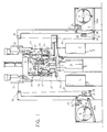
- Fig. 1 is a side elevational view of a blow molding apparatus embodying the invention.
- Fig. 2 is a fragmentary perspective schematic view embodying the apparatus.
- Fig. 3 is a fragmentary elevational schematic of a portion of the apparatus.
- Fig. 4 is a fragmentary elevational view on an enlarged scale of a portion of the apparatus shown in Fig. 1.
- Fig. 5 is a fragmentary side elevational view taken from the right side in Fig. 4.
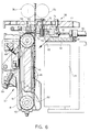
- Fig. 6 is a fragmentary sectional view on an enlarged scale taken along the line 6-6 in Fig. 5.
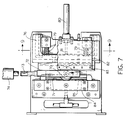
- Fig. 7 is a fragmentary bottom plan view of the apparatus shown in Fig. 6, parts being broken away.
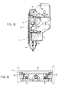
- Fig. 8 is a fragmentary rear elevational view of a portion of the apparatus shown in Fig. 10.
- Fig. 9 is a sectional view taken along the line 9-9 in Fig. 7.
- Fig. 10 is a fragmentary part sectional side elevational view taken from the left in Fig. 5.
- Fig. 11 is a part sectional side elevational view taken from the right in Fig. 10, parts being broken away.
- Fig. 12 is a fragmentary rear elevational view of the apparatus shown in Fig. 5.
- Fig. 13 is a fragmentary part sectional elevational view on an enlarged scale of another portion of the apparatus shown in Fig. 1.
- the invention relates to blow molded plastic articles such as containers wherein labels are applied to sections of a set of molds and the mold sections are closed and heated parisons or preforms are blown outwardly into conformity with the mold sections causing the labels to be adhered or bonded to the blown articles.
- the apparatus includes a plurality of sets of partible molds 20 in a linear array, that is, in side-by-side relationship.
- An extruder 21 is associated with each set of molds and a head 22 is moved downwardly to receive the end of an extruded tube in a neck mold in the head which is then drawn upwardly to position a preform or parison between the mold sections 20.
- the mold sections are then closed and the article blown to the desired configuration within the confines of the mold.
- the head 22 supports label deposit devices 24 as hereinafter described which deliver labels to the mold sections. If only one label is to be applied, a single deposit device 24 is provided for each set of molds.
- Labels are provided on the webs W of a roll R of label material such as plastic or paper on each side of the machine.
- the end of each web W is trained between a first set of driven pinch rollers 25 over an idler roller 27 and then under a roller 28 on a first pneumatically operated dancer arm 28a, and then between a second set of driven pinch rollers 29 and then under an idler roller 30 on a dancer arm 31.
- the web W passes from idler roller 30 upwardly over an idler roller 32 and horizontally over an idler roller 33, vertically to an idler roller 34 and then horizontally to an idler roller 35 and then downwardly between driven pinch rollers 36, on each side of the machine.
- the free end of the web W is then engaged by an endless vacuum conveyor 37, the belt of which moves to apply tension on the portion of the web between the driven rollers 36 and the conveyor 37.
- a knife assembly 38 is then actuated to sever the label from the portion under tension.
- the endless conveyor 37 then continues to operate until the label is centered on the endless conveyor 37. Thereafter, the endless conveyor 37 is moved bodily to bring the label adjacent an endless vacuum transfer conveyor 39 that extends horizontally.
- Endless transfer conveyor 39 is indexed horizontally relative to its respective conveyor 37. Successive labels are similarly severed and delivered to the conveyor 39 to provide an array of labels on the conveyor 39 corresponding to the number of cavities defined by mold sections 20 of the blow molding machine. Thereafter, the label deposit devices 24 function to remove the labels from the conveyor 39 and deposit them in the respective cavities of the mold sections 20.
- the endless conveyor 39 is driven intermittently by a motor M such as a stepping motor. Alternatively, the endless conveyor may be constructed and arranged in the manner set forth in the aforementioned EP-A-0 194 081.
- the first endless vacuum conveyor 37 comprises a frame 41 that supports vertically spaced rollers 42, 43 over which a perforated belt 44 is trained.
- the frame 41 supports a vacuum manifold 45 having openings 46 adjacent the belt 44 for applying vacuum to the belt 44.
- the belt 44 is driven intermittently by a motor 47 which, in turn, drives a pulley 48 and, in turn, pulleys 49, 50 through endless belts 51, 52, 53 to drive pulley 49 mounted on the shaft of upper roller 42.
- the motor M also functions to drive one of the pinch rollers 36 through a second endless belt 55 trained over the pulley 50 and another pulley 57 on the shaft of the one pinch roller 36.
- the frame 41 of the first endless vacuum conveyor is mounted on a fixed portion of the machine for movement horizontally and downwardly toward the second endless vacuum conveyor 39 and upwardly and outwardly away from the endless vacuum conveyor 39. Specifically, this is achieved by a pair of levers 60 which are pivoted at one end to a fixed portion of the machine and at the other end to the shaft of the upper roller 42 (Fig. 8).
- the lower end of the frame 41 supports rollers 61 that engage arcuate cam tracks 62 in the main frame which guide the lower end of the frame 41 and, in turn, the first vacuum conveyor 37 such that when the levers 60 are swung, the upper end of conveyor 37 is moved through an arc and the lower end of the conveyor moves in parallel fashion to the arc of movement of the upper end.
- an arm 63 is provided on the shaft 64 of the pulleys 50, 56.
- Shaft 64 supports a link 65.
- a pneumatic cylinder 66 has its piston rod 67 connected to the link 65 such that operation of the pneumatic cylinder 66 will cause the first conveyor to move between the first position shown in solid lines in Fig. 3 and a second position shown in broken lines in Fig. 3.
- a fixed stop 68 for frame 41 is provided on the main frame to determine the first position of conveyor 37.
- a second adjustable stop 69 in the form of a screw on the main frame permits adjustment of the second position of the conveyor 37.
- knife assembly 38 comprises a roller 70 which acts against an anvil 71 so that when the roller 70 is moved horizontally against a web on the anvil 71, a label is cut from the web.
- Roller 70 is rotatably mounted between the arms of a yoke 72 that is movable along anvil 71 by a link 73 which is operated by a linear motor 74.
- a slide 75 is supported on slide track 76 on frame 77 and supports a U-shaped bracket 78, the arms of which engage rollers 77 on the shaft of roller70.
- Springs 79 urge the slide 75 and, in turn, roller 70 against the anvil 71.
- a pneumatic cylinder 80 has its shaft 81 connected to slide 75 to position the slide 75 relative to the anvil 71.
- a first air chamber 82 is mounted on frame 76 and has downwardly and inwardly inclined openings 83 for directing air against the upper edge of the label which is being cut.
- a second air chamber 84 is mounted on the frame of the machine and has openings 85 for directing air against the other side of the web so that when a label is severed from the web, the label will not adhere to the anvil 71.
- the label deposit devices 24 on each side of the head 22 can be of various types, preferably vacuum pick-up and delivery devices, which function to pick up each label from the endless conveyor 39 and deliver it to the cavity of the mold.
- Each device includes a bar 90 that supports vacuum pads 91 and is supported by links 92 pivoted to the head 22 and actuated by a cylinder 93 which has its shaft 94 connected by a link 92 to move the vacuum cups toward conveyor 39 to pick up an array of labels and is retracted away from the conveyor 39 while the head moves adjacent the mold sections.
- the bars are moved outwardly to deposit the array of labels into the mold sections 20.
- the pads 91 are extended to deposit the array of labels to the mold cavities.
- the drive rollers are operated intermittently to bring the free edge of the web W in position for cutting a label from the web W.
- the first endless conveyor 37 is energized to cause the belt 44 to apply tension on the portion of the web between pinch roller 36 and the belt 44.
- the knife assembly is then actuated to cut off the label.
- the endless conveyor 37 continues to operate until the label is positioned centrally of a reach of belt 44 between rollers 42, 43.
- the cylinder 66 is then actuated to swing conveyor 37 bodily to a position adjacent conveyor 39 to transfer the label by interrupting or lowering the vacuum to belt 44.
- the conveyor 39 is then indexed and conveyor 37 is returned to its first position adjacent the pinch rollers 36 for a new cycle of severing another label and delivering it to the conveyor 39. Successive labels are cut and delivered to the conveyor 39 until an array of labels are provided on conveyor 39.
- the label deposit devices 24 are then actuated to simultaneously remove the array of labels from conveyor 39 so that they can be delivered simultaneously to the array of partible molds when head 22 moves downwardly.
- the movement of conveyor 37 can be adjusted to accommodate different size labels by moving the frame 41 relative to the main frame by adjusting screw 41a (Fig. 4).
Landscapes
- Engineering & Computer Science (AREA)
- Manufacturing & Machinery (AREA)
- Mechanical Engineering (AREA)
- Blow-Moulding Or Thermoforming Of Plastics Or The Like (AREA)
Claims (11)
- Verfahren zur Herstellung hohler Kunststoffartikel, bei dem ein Etikett in eine teilbare Gießform (20) einer Mehrzahl solcher im Abstand angeordneter Gießformen (20) positioniert wird, eine Vorform in der jeweiligen Satz der teilbaren Gießformen verbracht und die Gießformen geschlossen sowie die Vorform nach außen zu den Umgrenzungen der Gießform geblasen wird, um das Etikett an dem sich ergebenden hohlen Kunststoffartikel anzubringen, mit folgenden Schritten:
Auf einer Rolle von Etiketten (R) mit einem freien Ende sind Etiketten vorgesehen;
das freie Ende der Bahn (W) der Rolle der Etiketten wird aufeinanderfolgend ergriffen;
der Teil der Bahn (W) zwischen einer Stelle stromauf und dem freien Ende wird gespannt;
Etiketten werden aufeinanderfolgend von den gespannten Teilen ab- oder ausgeschnitten;
die jeweiligen Etiketten werden aufeinanderfolgend benachbart zu einem Förderer (39) übertragen;
das Etikett wird gleichzeitig ergriffen und aus einer ersten Stellung am Förderer (39) in eine zweite Stellung innerhalb der teilbaren Gießformen (20) verschoben;
das Etikett wird in die Gießformen abgelegt,
wobei der Schritt des Ab- oder Ausschneidens dadurch bewerkstelligt wird, daß die Bahn zwischen einer Rolle (70) und einem Amboß oder Gegenlager (71) verschoben wird und die Rolle (70) quer zu der Bahn bewegt wird, wobei Luft gegen die Seite der Bahn benachbart dem Gegenlager gerichtet wird, um das Anhaften der Bahn an dem Gegenlager zu vermeiden. - Verfahren nach Anspruch 1, dadurch gekennzeichnet, daß der Schritt des Spannens einem Teils der Bahn dadurch erzielt wird, daß die Bahn an der Stromaufstelle geklemmt wird.
- Verfahren nach Anspruch 1 oder 2, dadurch gekennzeichnet, daß nachfolgend jedem Schneiden von Etiketten von aufeinanderfolgend gespannten Teilen jedes Etikett aufeinanderfolgend benachbart einem endlosen Förderer (39) übertragen wird, daß der Förderer (39) aufeinanderfolgend indexiert wird, daß die Etiketten aufeinanderfolgend übergeben werden, um eine Anordnung von Etiketten vorzusehen, deren Abstand dem Abstand der Sätze der Gießformen (20) entspricht, daß die Anordnung der Etiketten gleichzeitig ergriffen und aus einer ersten Stellung auf dem Förderer (39) in eine zweite Stellung innerhalb der teilbaren Gießformen bewegt und daß die Anordnung der Etiketten gleichzeitig in den Gießformen abgelegt wird.
- Verfahren nach Anspruch 1 oder 2, dadurch gekennzeichnet, daß das freie Ende der Bahn der Rolle der Etiketten vom einem ersten endlosen Vakuumförderer (37) ergriffen, daß der Teil der Bahn zwischen der Stromaufstelle und dem freien Ende durch den ersten endlosen Förderer (37) gespannt wird, daß Etiketten von aufeinanderfolgend gespannten Teilen geschnitten werden, während die Vorderkante von dem ersten endlosen Vakuumförderer (37) ergriffen wird, daß das jeweilige Etikett aufeinanderfolgend benachbart einem zweiten endlosen Förderer (39) übertragen wird, daß der zweite endlose Förderer aufeinanderfolgend indexiert wird, um eine Anordnung von Etiketten vorzusehen, deren Abstand dem Abstand der Sätze der Gießformen entspricht, daß die Anordnung der Etiketten gleichzeitig ergriffen und aus der ersten Stellung auf dem zweiten Förderer in eine zweite Stellung innerhalb der teilbaren Gießformen bewegt wird und daß die Anordnung der Etiketten gleichzeitig in den Gießformen abgelegt wird.
- Verfahren nach Anspruch 4, dadurch gekennzeichnet, daß jedes Etikett aufeinanderfolgend dadurch übertragen wird, daß der erste endlose Förderer (37) mit einem Etikett darauf benachbart dem zweiten endlosen Förderer (39) bewegt wird.
- Verfahren nach Anspruch 5, dadurch gekennzeichnet, daß der Schritt der Bewegung des ersten endlosen Förderers dadurch erzielt wird, daß der erste endlose Förderer (37) körperlich zwischen einer ersten Stellung benachbart der Bahn und einer zweiten Stellung benachbart dem zweiten Förderer (39), hin und her schwingt.
- Vorrichtung zur Herstellung von hohlen Kunststoffartikeln durch ein Verfahren gemäß Anspruch 1, mit folgenden Merkmalen;
Eine Rolle von Etiketten (R) mit einem freien Ende, ein endloser Förderer (37) zum aufeinanderfolgenden Ergreifen des freien Endes der Bahn der Rolle der Etiketten und Spannen des Teils der Bahn zwischen einer Stromaufstelle und dem freien Ende durch den ersten endlosen Förderer,
eine Einrichtung zum aufeinanderfolgenden Schneiden von Etiketten von aufeinanderfolgend gespannten Teilen, und
eine Einrichtung zum aufeinanderfolgenden Übertragen der jeweiligen Etiketten in ein teilbare Gießform und Ablage in der Gießform, wobei die Einrichtung zum aufeinanderfolgenden Schneiden der Etiketten von aufeinanderfolgend gespannten Teilen eine Rolle (70), einen damit zusammenwirkender Amboß oder ein Gegenlager (71) und eine Einrichtung (73, 74) zur Verschiebung der Rolle quer zu der Bahn aufweist und wobei eine Einrichtung (84, 85) zum Richten von Luft gegen die Seite der Bahn benachbart dem Gegenlager (71) vorgesehen ist. - Vorrichtung nach Anspruch 7, die einen zweiten endlosen Förderer (39) im Winkel zu dem ersten Förderer (37) aufweist, ferner eine Einrichtung zum aufeinanderfolgenden Indexieren des zweiten endlosen Förderers, eine Einrichtung zum aufeinanderfolgenden Übertragen des jeweiligen Etikettes zum zweiten endlosen Förderer, der aufeinanderfolgend indexiert wird, um jedes Etikett aufeinanderfolgend abzunehmen und eine Anordnung von Etiketten auf dem zweiten endlosen Förderer vorzusehen, deren Abstand dem Abstand der Sätze der Gießformen entspricht, und schließlich eine Einrichtung zum gleichzeitigen Ergreifen der Anordnung der Etiketten und Bewegen aus einer ersten Stellung auf dem zweiten Förderer in eine zweite Stellung innerhalb einer teilbaren Gießform und Ablage der Etiketten in der Gießform.
- Vorrichtung nach Anspruch 8, bei der der erste und zweite endlose Förderer Vakuumförderer sind.
- Vorrichtung nach einem der Ansprüche 7 bis 9, welche Klemmrollen (36) an einer Stromaufstelle der Bahn umfaßt, um die Bahn zu Zwecken dem Spannens zu klemmen.
- Vorrichtung nach einem der Ansprüche 8 bis 10, welche eine Einrichtung (61, 62) zur Führung des ersten endlosen Förderers für die körperliche Schwingbewegung zwischen einer ersten Stellung benachbart der Bahn und einer zweiten Stellung benachbart dem zweiten endlosen Förderer umfaßt, während jedes Etikett zum zweiten endlosen Förderer übertragen wird.
Priority Applications (2)
| Application Number | Priority Date | Filing Date | Title |
|---|---|---|---|
| DE19883887883 DE3887883T2 (de) | 1988-07-29 | 1988-07-29 | Verfahren und Vorrichtung zum Anbringen von Etiketten auf blasgeformten Artikeln. |
| AT88307003T ATE101554T1 (de) | 1988-07-29 | 1988-07-29 | Verfahren und vorrichtung zum anbringen von etiketten auf blasgeformten artikeln. |
Applications Claiming Priority (2)
| Application Number | Priority Date | Filing Date | Title |
|---|---|---|---|
| US07/054,928 US4861541A (en) | 1987-05-28 | 1987-05-28 | Method for applying labels to blow molded articles |
| CA 574586 CA1324349C (en) | 1987-05-28 | 1988-08-12 | Method and apparatus for applying labels to blow molded articles |
Publications (2)
| Publication Number | Publication Date |
|---|---|
| EP0352384A1 EP0352384A1 (de) | 1990-01-31 |
| EP0352384B1 true EP0352384B1 (de) | 1994-02-16 |
Family
ID=25672047
Family Applications (1)
| Application Number | Title | Priority Date | Filing Date |
|---|---|---|---|
| EP19880307003 Expired - Lifetime EP0352384B1 (de) | 1987-05-28 | 1988-07-29 | Verfahren und Vorrichtung zum Anbringen von Etiketten auf blasgeformten Artikeln |
Country Status (5)
| Country | Link |
|---|---|
| US (2) | US4861541A (de) |
| EP (1) | EP0352384B1 (de) |
| AU (1) | AU592506B1 (de) |
| CA (1) | CA1324349C (de) |
| ES (1) | ES2049749T3 (de) |
Families Citing this family (14)
| Publication number | Priority date | Publication date | Assignee | Title |
|---|---|---|---|---|
| DE3908774A1 (de) * | 1989-03-17 | 1990-09-20 | Finnah Gmbh | Vorrichtung zum zufuehren eines etiketts in ein formnest einer formvorrichtung zum tiefziehen von kunststoffbehaeltnissen |
| US5082435A (en) * | 1989-06-23 | 1992-01-21 | Yoshida Industry Co., Ltd. | Transferring and molding apparatus |
| US5082439A (en) * | 1989-10-05 | 1992-01-21 | Owens-Illinois Plastic Products Inc. | Apparatus for applying labels in the molds of a plastic blow molding machine |
| US5032344A (en) * | 1989-10-05 | 1991-07-16 | Owens-Illinois Plastic Products Inc. | Method for applying labels in the molds of a plastic blow molding machine |
| AU650024B2 (en) * | 1990-07-13 | 1994-06-09 | Alto Manufacturing Pty Limited | In-mould label applicator |
| GB2262257B (en) * | 1990-07-13 | 1995-04-19 | Smith & Nephew Plastics | In-mould label applicator |
| US5918777A (en) * | 1996-02-21 | 1999-07-06 | Owens-Brockway Plastic Products Inc. | Dispensing package for viscous liquid product |
| US5968443A (en) * | 1996-03-01 | 1999-10-19 | The Clorox Company | Process for in-mold labelling |
| US6241128B1 (en) | 1998-12-22 | 2001-06-05 | Owens-Brockway Plastic Products Inc. | Dispenser package for fluent products and method of manufacture |
| US6394323B2 (en) | 1999-08-24 | 2002-05-28 | Owens-Brockway Plastic Products Inc. | Dispenser package for fluent products and method of manufacture |
| US6311878B1 (en) | 2000-01-07 | 2001-11-06 | Owens-Brockway Plastics Products Inc. | Dispensing package for fluent products |
| JP2004261977A (ja) * | 2003-02-18 | 2004-09-24 | Yoshida Industry Co Ltd | 両面インモールド転写成形方法 |
| CA2697782C (en) * | 2007-07-30 | 2015-12-22 | Procaps S.A. | Method and apparatus for printing on soft gelatin capsules during forming |
| EP4301563A1 (de) * | 2021-03-05 | 2024-01-10 | Avery Dennison Retail Information Services LLC | Schneidsysteme und -verfahren mit variabler länge |
Family Cites Families (14)
| Publication number | Priority date | Publication date | Assignee | Title |
|---|---|---|---|---|
| US3292209A (en) * | 1963-12-10 | 1966-12-20 | American Can Co | Labeling apparatus |
| CH549478A (de) * | 1973-03-09 | 1974-05-31 | Grapha Holding Ag | Tast- und markiervorrichtung an einer adressiermaschine. |
| EP0018457B1 (de) * | 1978-12-05 | 1984-05-16 | Associpak International Inc. | Etikettieranlage |
| AU537548B2 (en) * | 1979-12-03 | 1984-06-28 | Dow Corning Corporation | Mercaptoorganopolysiloxane elastomers catalyzed by metallic compounds in the presence of peroxides |
| US4355967A (en) * | 1980-09-30 | 1982-10-26 | The Continental Group, Inc. | Label applying device |
| IT1136878B (it) * | 1981-04-01 | 1986-09-03 | Leptons Italia Srl | Procedimento e apparecchiatura atti ad eseguire il taglio di etichette e/o cartellini da un nastro continuo in successione alla relativa stampa |
| GB2170178A (en) * | 1984-12-21 | 1986-07-30 | Stackpole Machinery Ltd | Roll fed labelling machine |
| US4636166A (en) * | 1985-03-01 | 1987-01-13 | Owens-Illinois, Inc. | Apparatus for applying labels to blow molded articles |
| US4585408A (en) * | 1985-04-11 | 1986-04-29 | Plastipak Packaging, Inc. | In-mold label dispenser for plastic blow molding machine |
| US4679997A (en) * | 1985-11-25 | 1987-07-14 | Owens-Illinois, Inc. | Apparatus for delivering labels to blow molds of a plastic container blowing machine and removing the blown containers with the labels thereon |
| US4680000A (en) * | 1985-11-25 | 1987-07-14 | Owens-Illinois, Inc. | Apparatus for applying labels in the molds of a plastic blow molding machine |
| US4721451A (en) * | 1987-03-31 | 1988-01-26 | Plastipak Packaging, Inc. | In-mold label dispenser for plastic blow molding |
| US4737099A (en) * | 1987-06-25 | 1988-04-12 | Owens-Illinois Plastic Products Inc. | Apparatus for applying labels to blow molded articles |
| US4787833A (en) * | 1987-07-31 | 1988-11-29 | Owens-Illinois Plastic Products Inc. | Apparatus for applying labels to blow molded articles |
-
1987
- 1987-05-28 US US07/054,928 patent/US4861541A/en not_active Expired - Lifetime
-
1988
- 1988-07-29 ES ES88307003T patent/ES2049749T3/es not_active Expired - Lifetime
- 1988-07-29 EP EP19880307003 patent/EP0352384B1/de not_active Expired - Lifetime
- 1988-08-02 AU AU20338/88A patent/AU592506B1/en not_active Ceased
- 1988-08-12 CA CA 574586 patent/CA1324349C/en not_active Expired - Fee Related
-
1989
- 1989-04-03 US US07/332,089 patent/US4911635A/en not_active Expired - Lifetime
Also Published As
| Publication number | Publication date |
|---|---|
| US4861541A (en) | 1989-08-29 |
| US4911635A (en) | 1990-03-27 |
| AU592506B1 (en) | 1990-01-11 |
| ES2049749T3 (es) | 1994-05-01 |
| CA1324349C (en) | 1993-11-16 |
| EP0352384A1 (de) | 1990-01-31 |
Similar Documents
| Publication | Publication Date | Title |
|---|---|---|
| US5032344A (en) | Method for applying labels in the molds of a plastic blow molding machine | |
| US4861541A (en) | Method for applying labels to blow molded articles | |
| US4737099A (en) | Apparatus for applying labels to blow molded articles | |
| CA1249909A (en) | Applying labels to blow molded articles | |
| EP0421642B1 (de) | Vorrichtung und Verfahren zum Einbringen von Etiketten in die Formen einer Blasformmaschine | |
| US5082439A (en) | Apparatus for applying labels in the molds of a plastic blow molding machine | |
| JPH01240409A (ja) | カラーを有するヒンジ蓋付き・煙草パッケージの製造装置 | |
| US4853169A (en) | Method for applying labels to blow molded articles | |
| US5017125A (en) | Apparatus for feeding a label to a cavity of a molding device for thermoforming plastic containers | |
| US4824630A (en) | Method and apparatus for applying labels in the molds of a plastic blow molding machine | |
| US4787833A (en) | Apparatus for applying labels to blow molded articles | |
| US6334766B1 (en) | Takeout apparatus for shuttle-type plastic blow moulding machines | |
| JPH0622870B2 (ja) | パリソンの吹込成形装置 | |
| CN111136894A (zh) | 一种把手预热吹瓶生产线及其方法 | |
| DK154285B (da) | Fremgangsmaade og apparat til emballering af rumlige genstande | |
| DE3887883T2 (de) | Verfahren und Vorrichtung zum Anbringen von Etiketten auf blasgeformten Artikeln. | |
| JPH0617058B2 (ja) | 吹込成形物にラベルを取付ける方法および装置 | |
| US3794454A (en) | Apparatus for automatically trim finishing blow molded plastic articles | |
| EP1144250B1 (de) | Vorrichtung und verfahren zum aufbringen von endlosen bändern auf kartons | |
| JP3442141B2 (ja) | 吹き込み成形装置 | |
| CA2359988A1 (en) | Take-out apparatus for plastic moulding machines | |
| JPH0560776B2 (de) |
Legal Events
| Date | Code | Title | Description |
|---|---|---|---|
| PUAI | Public reference made under article 153(3) epc to a published international application that has entered the european phase |
Free format text: ORIGINAL CODE: 0009012 |
|
| AK | Designated contracting states |
Kind code of ref document: A1 Designated state(s): AT BE CH DE ES FR GB GR IT LI LU NL SE |
|
| 17P | Request for examination filed |
Effective date: 19900403 |
|
| 17Q | First examination report despatched |
Effective date: 19911216 |
|
| GRAA | (expected) grant |
Free format text: ORIGINAL CODE: 0009210 |
|
| ITF | It: translation for a ep patent filed | ||
| AK | Designated contracting states |
Kind code of ref document: B1 Designated state(s): AT BE CH DE ES FR GB GR IT LI LU NL SE |
|
| PG25 | Lapsed in a contracting state [announced via postgrant information from national office to epo] |
Ref country code: SE Effective date: 19940216 Ref country code: LI Effective date: 19940216 Ref country code: GR Free format text: LAPSE BECAUSE OF FAILURE TO SUBMIT A TRANSLATION OF THE DESCRIPTION OR TO PAY THE FEE WITHIN THE PRESCRIBED TIME-LIMIT Effective date: 19940216 Ref country code: CH Effective date: 19940216 Ref country code: AT Effective date: 19940216 |
|
| REF | Corresponds to: |
Ref document number: 101554 Country of ref document: AT Date of ref document: 19940315 Kind code of ref document: T |
|
| ET | Fr: translation filed | ||
| REF | Corresponds to: |
Ref document number: 3887883 Country of ref document: DE Date of ref document: 19940324 |
|
| REG | Reference to a national code |
Ref country code: ES Ref legal event code: FG2A Ref document number: 2049749 Country of ref document: ES Kind code of ref document: T3 |
|
| REG | Reference to a national code |
Ref country code: CH Ref legal event code: PL |
|
| PG25 | Lapsed in a contracting state [announced via postgrant information from national office to epo] |
Ref country code: LU Free format text: LAPSE BECAUSE OF NON-PAYMENT OF DUE FEES Effective date: 19940731 |
|
| PLBE | No opposition filed within time limit |
Free format text: ORIGINAL CODE: 0009261 |
|
| STAA | Information on the status of an ep patent application or granted ep patent |
Free format text: STATUS: NO OPPOSITION FILED WITHIN TIME LIMIT |
|
| 26N | No opposition filed | ||
| PGFP | Annual fee paid to national office [announced via postgrant information from national office to epo] |
Ref country code: NL Payment date: 19950707 Year of fee payment: 8 |
|
| PGFP | Annual fee paid to national office [announced via postgrant information from national office to epo] |
Ref country code: BE Payment date: 19950807 Year of fee payment: 8 |
|
| PGFP | Annual fee paid to national office [announced via postgrant information from national office to epo] |
Ref country code: GB Payment date: 19960617 Year of fee payment: 9 |
|
| PGFP | Annual fee paid to national office [announced via postgrant information from national office to epo] |
Ref country code: ES Payment date: 19960715 Year of fee payment: 9 |
|
| PG25 | Lapsed in a contracting state [announced via postgrant information from national office to epo] |
Ref country code: BE Effective date: 19960731 |
|
| BERE | Be: lapsed |
Owner name: OWENS-ILLINOIS PLASTIC PRODUCTS INC. Effective date: 19960731 |
|
| PG25 | Lapsed in a contracting state [announced via postgrant information from national office to epo] |
Ref country code: NL Effective date: 19970201 |
|
| NLV4 | Nl: lapsed or anulled due to non-payment of the annual fee |
Effective date: 19970201 |
|
| PG25 | Lapsed in a contracting state [announced via postgrant information from national office to epo] |
Ref country code: GB Free format text: LAPSE BECAUSE OF NON-PAYMENT OF DUE FEES Effective date: 19970729 |
|
| PG25 | Lapsed in a contracting state [announced via postgrant information from national office to epo] |
Ref country code: ES Free format text: LAPSE BECAUSE OF EXPIRATION OF PROTECTION Effective date: 19970730 |
|
| GBPC | Gb: european patent ceased through non-payment of renewal fee |
Effective date: 19970729 |
|
| PGFP | Annual fee paid to national office [announced via postgrant information from national office to epo] |
Ref country code: FR Payment date: 19990707 Year of fee payment: 12 |
|
| PGFP | Annual fee paid to national office [announced via postgrant information from national office to epo] |
Ref country code: DE Payment date: 19990730 Year of fee payment: 12 |
|
| REG | Reference to a national code |
Ref country code: ES Ref legal event code: FD2A Effective date: 20010201 |
|
| PG25 | Lapsed in a contracting state [announced via postgrant information from national office to epo] |
Ref country code: FR Free format text: LAPSE BECAUSE OF NON-PAYMENT OF DUE FEES Effective date: 20010330 |
|
| REG | Reference to a national code |
Ref country code: FR Ref legal event code: ST |
|
| PG25 | Lapsed in a contracting state [announced via postgrant information from national office to epo] |
Ref country code: DE Free format text: LAPSE BECAUSE OF NON-PAYMENT OF DUE FEES Effective date: 20010501 |
|
| PG25 | Lapsed in a contracting state [announced via postgrant information from national office to epo] |
Ref country code: IT Free format text: LAPSE BECAUSE OF NON-PAYMENT OF DUE FEES;WARNING: LAPSES OF ITALIAN PATENTS WITH EFFECTIVE DATE BEFORE 2007 MAY HAVE OCCURRED AT ANY TIME BEFORE 2007. THE CORRECT EFFECTIVE DATE MAY BE DIFFERENT FROM THE ONE RECORDED. Effective date: 20050729 |