EP0352417A2 - Dispositif de commande avec un manche de commande - Google Patents
Dispositif de commande avec un manche de commande Download PDFInfo
- Publication number
- EP0352417A2 EP0352417A2 EP89108365A EP89108365A EP0352417A2 EP 0352417 A2 EP0352417 A2 EP 0352417A2 EP 89108365 A EP89108365 A EP 89108365A EP 89108365 A EP89108365 A EP 89108365A EP 0352417 A2 EP0352417 A2 EP 0352417A2
- Authority
- EP
- European Patent Office
- Prior art keywords
- control
- sleeve
- signal transmitter
- cylinder
- roll
- Prior art date
- Legal status (The legal status is an assumption and is not a legal conclusion. Google has not performed a legal analysis and makes no representation as to the accuracy of the status listed.)
- Withdrawn
Links
Images

Classifications
-
- B—PERFORMING OPERATIONS; TRANSPORTING
- B64—AIRCRAFT; AVIATION; COSMONAUTICS
- B64C—AEROPLANES; HELICOPTERS
- B64C13/00—Control systems or transmitting systems for actuating flying-control surfaces, lift-increasing flaps, air brakes, or spoilers
- B64C13/02—Initiating means
- B64C13/04—Initiating means actuated personally
- B64C13/042—Initiating means actuated personally operated by hand
- B64C13/0421—Initiating means actuated personally operated by hand control sticks for primary flight controls
-
- G—PHYSICS
- G05—CONTROLLING; REGULATING
- G05G—CONTROL DEVICES OR SYSTEMS INSOFAR AS CHARACTERISED BY MECHANICAL FEATURES ONLY
- G05G25/00—Other details or appurtenances of control mechanisms, e.g. supporting intermediate members elastically
- G05G25/02—Inhibiting the generation or transmission of noise
-
- G—PHYSICS
- G05—CONTROLLING; REGULATING
- G05G—CONTROL DEVICES OR SYSTEMS INSOFAR AS CHARACTERISED BY MECHANICAL FEATURES ONLY
- G05G5/00—Means for preventing, limiting or returning the movements of parts of a control mechanism, e.g. locking controlling member
- G05G5/05—Means for returning or tending to return controlling members to an inoperative or neutral position, e.g. by providing return springs or resilient end-stops
-
- G—PHYSICS
- G05—CONTROLLING; REGULATING
- G05G—CONTROL DEVICES OR SYSTEMS INSOFAR AS CHARACTERISED BY MECHANICAL FEATURES ONLY
- G05G9/00—Manually-actuated control mechanisms provided with one single controlling member co-operating with two or more controlled members, e.g. selectively, simultaneously
- G05G9/02—Manually-actuated control mechanisms provided with one single controlling member co-operating with two or more controlled members, e.g. selectively, simultaneously the controlling member being movable in different independent ways, movement in each individual way actuating one controlled member only
- G05G9/04—Manually-actuated control mechanisms provided with one single controlling member co-operating with two or more controlled members, e.g. selectively, simultaneously the controlling member being movable in different independent ways, movement in each individual way actuating one controlled member only in which movement in two or more ways can occur simultaneously
- G05G9/047—Manually-actuated control mechanisms provided with one single controlling member co-operating with two or more controlled members, e.g. selectively, simultaneously the controlling member being movable in different independent ways, movement in each individual way actuating one controlled member only in which movement in two or more ways can occur simultaneously the controlling member being movable by hand about orthogonal axes, e.g. joysticks
-
- G—PHYSICS
- G05—CONTROLLING; REGULATING
- G05G—CONTROL DEVICES OR SYSTEMS INSOFAR AS CHARACTERISED BY MECHANICAL FEATURES ONLY
- G05G9/00—Manually-actuated control mechanisms provided with one single controlling member co-operating with two or more controlled members, e.g. selectively, simultaneously
- G05G9/02—Manually-actuated control mechanisms provided with one single controlling member co-operating with two or more controlled members, e.g. selectively, simultaneously the controlling member being movable in different independent ways, movement in each individual way actuating one controlled member only
- G05G9/04—Manually-actuated control mechanisms provided with one single controlling member co-operating with two or more controlled members, e.g. selectively, simultaneously the controlling member being movable in different independent ways, movement in each individual way actuating one controlled member only in which movement in two or more ways can occur simultaneously
- G05G9/047—Manually-actuated control mechanisms provided with one single controlling member co-operating with two or more controlled members, e.g. selectively, simultaneously the controlling member being movable in different independent ways, movement in each individual way actuating one controlled member only in which movement in two or more ways can occur simultaneously the controlling member being movable by hand about orthogonal axes, e.g. joysticks
- G05G2009/04703—Mounting of controlling member
- G05G2009/04714—Mounting of controlling member with orthogonal axes
- G05G2009/04718—Mounting of controlling member with orthogonal axes with cardan or gimbal type joint
-
- G—PHYSICS
- G05—CONTROLLING; REGULATING
- G05G—CONTROL DEVICES OR SYSTEMS INSOFAR AS CHARACTERISED BY MECHANICAL FEATURES ONLY
- G05G9/00—Manually-actuated control mechanisms provided with one single controlling member co-operating with two or more controlled members, e.g. selectively, simultaneously
- G05G9/02—Manually-actuated control mechanisms provided with one single controlling member co-operating with two or more controlled members, e.g. selectively, simultaneously the controlling member being movable in different independent ways, movement in each individual way actuating one controlled member only
- G05G9/04—Manually-actuated control mechanisms provided with one single controlling member co-operating with two or more controlled members, e.g. selectively, simultaneously the controlling member being movable in different independent ways, movement in each individual way actuating one controlled member only in which movement in two or more ways can occur simultaneously
- G05G9/047—Manually-actuated control mechanisms provided with one single controlling member co-operating with two or more controlled members, e.g. selectively, simultaneously the controlling member being movable in different independent ways, movement in each individual way actuating one controlled member only in which movement in two or more ways can occur simultaneously the controlling member being movable by hand about orthogonal axes, e.g. joysticks
- G05G2009/0474—Manually-actuated control mechanisms provided with one single controlling member co-operating with two or more controlled members, e.g. selectively, simultaneously the controlling member being movable in different independent ways, movement in each individual way actuating one controlled member only in which movement in two or more ways can occur simultaneously the controlling member being movable by hand about orthogonal axes, e.g. joysticks characterised by means converting mechanical movement into electric signals
- G05G2009/04748—Position sensor for rotary movement, e.g. potentiometer
Definitions
- the invention relates to a control device according to the preamble of patent claim 1.
- the invention is therefore based on the object of effecting an artificial control feeling for the pilot or the like when operating the control stick in a control device of the type mentioned in a mechanical way with high reliability.
- a gimbal joint bearing is provided for the control stick in such a configuration that it enables an integration of both the electrical control signal transmitter and reliable mechanical force and torque means into a compact unit with a constant translation of the control inputs between the control stick and the control signal transmitters. It can be ensured by the spring-force working cylinder characterized in claim 2 without further ado that the control stick is returned to its zero position (rest position) without play and reproducibly after each actuation.
- the rotary motion damper in the embodiment characterized in claim 5 can abruptly exclude abrupt movements of the control stick per control axis, such as an unintentional sudden snap back from an actuation, and an overshoot thereof.
- an electrical pitch or roll control signal transmitter 2 or 3 is assigned to a control stick 1 in the control device according to FIG. 1, e.g. inductive angle encoder.
- the control movements of the joystick 1 about the pitch and roll axis 4 or 5 are transmitted to the assigned pitch - or roll control signal transmitter 2 or 3 by means of a cardan joint bearing, the rotational mobility of which is limited around both control axes:
- control stick 1 is fixedly arranged on a control shaft 6, which is coaxial with the roll axis 5, for the roll control signal transmitter 3 and is mounted in a control frame 7. Its rotational mobility about the pitch axis 4 is due to a bearing in a support frame 8 by means of two bearing journals 9, which are arranged at right angles to the joystick 1 and are coaxial with the pitch axis 4 ensured.
- the pitch control signal transmitter 2 is actuated via one of these rotatable pivot pins 9.
- control shaft 6 is coupled via a lever 10 fixed thereon to a spring-force working cylinder 11 which, on the other hand, is articulated in an axis-parallel arrangement to the control stick 1 on a cantilever arm 7.1 of the control frame 7.
- a control damper 12 is interposed between the control shaft 6 and the roll control signal generator 3.
- a spring-force working cylinder 13 is decisive for the rotational mobility of the control frame 7, which is actuated via a lever extension 7.2 of the control frame 7 that is perpendicular to the pitch axis 4 and, on the other hand, is articulated in a parallel arrangement to the roll axis 5 on the support frame 8.
- a rotary damper 14 is assigned to one of the rotatable bearing pins 9.
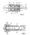
- the individual spring-force working cylinder in the cylinder space according to FIG. 2 has a cylinder bottom surface 16 facing its actuating end 15.1 of its piston rod 15 through its piston slide 17 displaceable sleeve 18 and a first compression spring 19 arranged therein around the piston rod 15, which is supported, preferably under a predetermined pressure preload, on the one hand against the piston slide 17 and on the other hand against a sleeve end base 18.1.
- the displaceability of the sleeve 18 is limited by a second, preferably also prestressed, compression spring 20, which is arranged around the piston rod 15 between the sleeve 18 and the second cylinder base surface 16.1 facing away from the actuating end 15.1 of the piston rod 15.
- a third (preferably preloaded) compression spring 21 is provided for simulating a deflection force of the control stick 1 with overstroke, which is why the second compression spring 20 together with the sleeve 18 of the first compression spring 19 in one - from the rest position at the actuating end 15.1 of the piston rod 15 facing cylinder bottom surface 16 is displaceable by this sleeve 18 - second sleeve 22 is enclosed.
- the sleeve bottom 22.1 facing away from the actuating end 15.1 of the piston rod 15 is instead of the second cylinder bottom surface 16.1 the support base of the second compression spring 20, the displaceability of the second sleeve 22 being limited by the third compression spring 21 arranged around it between a support surface 22.1 thereof and the second cylinder base surface 16.1.
- the cylinder space expediently has a greater overall length than the sleeve 22 by the length of the displacement path determined by the second sleeve 22.
- the rotary motion damper 14 or 12 according to FIG. 3, which is provided for each control axis 4, 5 or spring-loaded working cylinder 13 or 11, is of such a construction that changes in the damping effect are excluded even under considerable temperature fluctuations.
- a cylindrical housing 23 which is closed like a pot in one rotary motion damper 14 in accordance with the right partial view of FIG. 3, but in the other rotary motion damper 12 is configured identically at both ends in accordance with the left partial view of FIG.
- the rotor 24 is supported in such a way that an outwardly tight annular gap 25 with a small width b, approximately one tenth of a millimeter at a normal temperature of approximately 20 ° C., is bounded, which is sealed with a damping fluid, not shown, for example Silicone oil, is filled.
- the housing 23 and the rotor 24 consist of material which is so different with regard to their temperature-dependent expansion coefficient that, given the viscosity of the damping liquid, the annular gap width b changes with temperature changes in the sense of a constant damping effect.
- aluminum can be selected as the material for the housing 23 and polytetrafluoroethylene as the material for the rotor 24.
Landscapes
- Engineering & Computer Science (AREA)
- Automation & Control Theory (AREA)
- Physics & Mathematics (AREA)
- General Physics & Mathematics (AREA)
- Aviation & Aerospace Engineering (AREA)
- Mechanical Control Devices (AREA)
Applications Claiming Priority (2)
| Application Number | Priority Date | Filing Date | Title |
|---|---|---|---|
| DE3825809 | 1988-07-29 | ||
| DE3825809A DE3825809A1 (de) | 1988-07-29 | 1988-07-29 | Steuereinrichtung mit einem steuerknueppel |
Publications (2)
| Publication Number | Publication Date |
|---|---|
| EP0352417A2 true EP0352417A2 (fr) | 1990-01-31 |
| EP0352417A3 EP0352417A3 (fr) | 1990-08-22 |
Family
ID=6359841
Family Applications (1)
| Application Number | Title | Priority Date | Filing Date |
|---|---|---|---|
| EP89108365A Withdrawn EP0352417A3 (fr) | 1988-07-29 | 1989-05-10 | Dispositif de commande avec un manche de commande |
Country Status (2)
| Country | Link |
|---|---|
| EP (1) | EP0352417A3 (fr) |
| DE (1) | DE3825809A1 (fr) |
Cited By (19)
| Publication number | Priority date | Publication date | Assignee | Title |
|---|---|---|---|---|
| US5125602A (en) * | 1989-02-20 | 1992-06-30 | Aerospatiale Societe Nationale Industrielle | Tilting stick control device, especially for an aircraft, and system comprising two such devices |
| WO2007132267A1 (fr) * | 2006-05-12 | 2007-11-22 | Bae Systems Plc | Perfectionnements à un appareil à tige active ou s'y rapportant |
| KR100842816B1 (ko) * | 2003-09-19 | 2008-07-01 | 국방과학연구소 | 센터링 스프링 장치 |
| WO2008064117A3 (fr) * | 2006-11-20 | 2008-07-24 | Honeywell Int Inc | Cardan entièrement flottant à alignement et réglage automatiques destiné à une interface active homme-machine |
| EP2081098A2 (fr) | 2008-01-18 | 2009-07-22 | Honeywell International Inc. | Appareil pour la fixation réversible d'un objet rotatif dans une position prédéterminée |
| KR100995014B1 (ko) | 2010-03-23 | 2010-11-17 | 주식회사 흥국 | 칼라 압입기 및 이를 구비하는 무한궤도용 롤러 조립장치 |
| JP2010535667A (ja) * | 2007-08-08 | 2010-11-25 | ムーグ インコーポレーテッド | フライバイワイヤ飛行制御システムでの使用に適合した操縦桿及びそれに使用する連結機構 |
| EP2341410A1 (fr) * | 2010-01-04 | 2011-07-06 | Guillemot Corporation | Joystick à ressorts de compensation, procédé de fabrication et manette correspondants |
| FR2965870A1 (fr) * | 2010-10-06 | 2012-04-13 | Skf Ab | Ensemble de liaison pour joint de transmission et joint de transmission associe |
| EP2626296A1 (fr) * | 2012-02-10 | 2013-08-14 | Bell Helicopter Textron Inc. | Système de commande pilote avec mécanisme de cardan compact |
| CN103241375A (zh) * | 2012-02-10 | 2013-08-14 | 贝尔直升机德事隆公司 | 带有可调节踏板的飞行员控制系统 |
| US8812177B2 (en) | 2012-02-10 | 2014-08-19 | Bell Helicopter Textron Inc. | Integrated aircraft flight control units |
| CN104520183A (zh) * | 2012-06-07 | 2015-04-15 | 萨基姆防务安全公司 | 用于控制飞机的操纵杆 |
| US9056675B2 (en) | 2012-02-10 | 2015-06-16 | Bell Helicopter Textron Inc. | Pilot control system with hand rest |
| US9067672B2 (en) | 2012-02-10 | 2015-06-30 | Bell Helicopter Textron Inc. | Pilot control system with pendent grip |
| US9120557B2 (en) | 2012-03-27 | 2015-09-01 | Ratier Figeac | Piloting device for piloting a vehicle, in particular an aircraft |
| RU2643856C2 (ru) * | 2013-10-15 | 2018-02-06 | Сажем Дефанс Секюрите | Устройство управления полетом для летательного аппарата |
| EP3324072A1 (fr) * | 2016-11-21 | 2018-05-23 | Ratier-Figeac SAS | Ensemble amortisseur |
| CN113632040A (zh) * | 2019-01-31 | 2021-11-09 | 雷蛇(亚太)私人有限公司 | 感应式操纵杆 |
Families Citing this family (2)
| Publication number | Priority date | Publication date | Assignee | Title |
|---|---|---|---|---|
| DE19719591C2 (de) * | 1997-05-09 | 1999-12-16 | Bodenseewerk Geraetetech | Passiver Steuerknüppel für Flugzeuge |
| CN107416186A (zh) | 2017-04-06 | 2017-12-01 | 中国商用飞机有限责任公司 | 飞机的电动脚蹬控制装置 |
Family Cites Families (5)
| Publication number | Priority date | Publication date | Assignee | Title |
|---|---|---|---|---|
| DE675000C (de) * | 1934-11-18 | 1939-04-29 | E H Dr Phil H C Ernst Heinkel | Hoehensteuerung fuer Flugzeuge |
| US3523665A (en) * | 1968-02-19 | 1970-08-11 | Martin Marietta Corp | Side stick |
| DE2234563C3 (de) * | 1972-07-14 | 1979-10-25 | Vereinigte Flugtechnische Werkefokker Gmbh, 2800 Bremen | Stellanordnung zur Einstellung einer Steuerfläche |
| US4367373A (en) * | 1981-04-07 | 1983-01-04 | The United States Of America As Represented By The Secretary Of The Air Force | Two-axis electromechanical controller |
| SE431432B (sv) * | 1982-06-01 | 1984-02-06 | Saab Scania Ab | Styrdon |
-
1988
- 1988-07-29 DE DE3825809A patent/DE3825809A1/de active Granted
-
1989
- 1989-05-10 EP EP89108365A patent/EP0352417A3/fr not_active Withdrawn
Cited By (33)
| Publication number | Priority date | Publication date | Assignee | Title |
|---|---|---|---|---|
| US5125602A (en) * | 1989-02-20 | 1992-06-30 | Aerospatiale Societe Nationale Industrielle | Tilting stick control device, especially for an aircraft, and system comprising two such devices |
| KR100842816B1 (ko) * | 2003-09-19 | 2008-07-01 | 국방과학연구소 | 센터링 스프링 장치 |
| EP2284641A1 (fr) * | 2006-05-12 | 2011-02-16 | BAE Systems PLC | Améliorations concernant un levier de contrôle actif |
| WO2007132267A1 (fr) * | 2006-05-12 | 2007-11-22 | Bae Systems Plc | Perfectionnements à un appareil à tige active ou s'y rapportant |
| US8079281B2 (en) | 2006-05-12 | 2011-12-20 | Bae Systems Plc | Active stick apparatus |
| WO2008064117A3 (fr) * | 2006-11-20 | 2008-07-24 | Honeywell Int Inc | Cardan entièrement flottant à alignement et réglage automatiques destiné à une interface active homme-machine |
| US8033197B2 (en) | 2006-11-20 | 2011-10-11 | Honeywell International Inc. | Fully floating, self-aligning, self-adjusting gimbal assembly for an active human machine interface |
| JP2010535667A (ja) * | 2007-08-08 | 2010-11-25 | ムーグ インコーポレーテッド | フライバイワイヤ飛行制御システムでの使用に適合した操縦桿及びそれに使用する連結機構 |
| US7866230B2 (en) | 2008-01-18 | 2011-01-11 | Honeywell International Inc. | Apparatus for releasably securing a rotatable object in a predetermined position |
| EP2081098A3 (fr) * | 2008-01-18 | 2010-01-20 | Honeywell International Inc. | Appareil pour la fixation réversible d'un objet rotatif dans une position prédéterminée |
| EP2081098A2 (fr) | 2008-01-18 | 2009-07-22 | Honeywell International Inc. | Appareil pour la fixation réversible d'un objet rotatif dans une position prédéterminée |
| EP2341410A1 (fr) * | 2010-01-04 | 2011-07-06 | Guillemot Corporation | Joystick à ressorts de compensation, procédé de fabrication et manette correspondants |
| FR2954980A1 (fr) * | 2010-01-04 | 2011-07-08 | Guillemot Corp | Joystick a ressorts de compensation, procede de fabrication et manette correspondants. |
| KR100995014B1 (ko) | 2010-03-23 | 2010-11-17 | 주식회사 흥국 | 칼라 압입기 및 이를 구비하는 무한궤도용 롤러 조립장치 |
| FR2965870A1 (fr) * | 2010-10-06 | 2012-04-13 | Skf Ab | Ensemble de liaison pour joint de transmission et joint de transmission associe |
| CN103241375A (zh) * | 2012-02-10 | 2013-08-14 | 贝尔直升机德事隆公司 | 带有可调节踏板的飞行员控制系统 |
| EP2626296A1 (fr) * | 2012-02-10 | 2013-08-14 | Bell Helicopter Textron Inc. | Système de commande pilote avec mécanisme de cardan compact |
| US8812177B2 (en) | 2012-02-10 | 2014-08-19 | Bell Helicopter Textron Inc. | Integrated aircraft flight control units |
| US9764830B2 (en) | 2012-02-10 | 2017-09-19 | Bell Helicopter Textron Inc. | Pilot control system with adjustable pedals |
| US9051836B2 (en) | 2012-02-10 | 2015-06-09 | Bell Helicopter Textron Inc. | Pilot control system with compact gimbal mechanism |
| US9056675B2 (en) | 2012-02-10 | 2015-06-16 | Bell Helicopter Textron Inc. | Pilot control system with hand rest |
| US9067672B2 (en) | 2012-02-10 | 2015-06-30 | Bell Helicopter Textron Inc. | Pilot control system with pendent grip |
| CN103241375B (zh) * | 2012-02-10 | 2015-10-28 | 贝尔直升机德事隆公司 | 旋翼飞行器、踏板组件及调节飞行器踏板组件的方法 |
| US9120557B2 (en) | 2012-03-27 | 2015-09-01 | Ratier Figeac | Piloting device for piloting a vehicle, in particular an aircraft |
| CN104520183B (zh) * | 2012-06-07 | 2016-04-13 | 萨基姆防务安全公司 | 用于控制飞机的操纵杆 |
| CN104520183A (zh) * | 2012-06-07 | 2015-04-15 | 萨基姆防务安全公司 | 用于控制飞机的操纵杆 |
| RU2643856C2 (ru) * | 2013-10-15 | 2018-02-06 | Сажем Дефанс Секюрите | Устройство управления полетом для летательного аппарата |
| EP3324072A1 (fr) * | 2016-11-21 | 2018-05-23 | Ratier-Figeac SAS | Ensemble amortisseur |
| US10436278B2 (en) * | 2016-11-21 | 2019-10-08 | Ratier-Figeac Sas | Damping assembly |
| CN113632040A (zh) * | 2019-01-31 | 2021-11-09 | 雷蛇(亚太)私人有限公司 | 感应式操纵杆 |
| EP3918440A4 (fr) * | 2019-01-31 | 2022-03-02 | Razer (Asia-Pacific) Pte. Ltd. | Manette inductive |
| CN113632040B (zh) * | 2019-01-31 | 2023-09-29 | 雷蛇(亚太)私人有限公司 | 感应式操纵杆 |
| US11782473B2 (en) | 2019-01-31 | 2023-10-10 | Razer (Asia-Pacific) Pte. Ltd. | Inductive joystick |
Also Published As
| Publication number | Publication date |
|---|---|
| DE3825809C2 (fr) | 1990-05-31 |
| DE3825809A1 (de) | 1990-02-08 |
| EP0352417A3 (fr) | 1990-08-22 |
Similar Documents
| Publication | Publication Date | Title |
|---|---|---|
| EP0352417A2 (fr) | Dispositif de commande avec un manche de commande | |
| DE3510957A1 (de) | Redundanz-servoantrieb, insbesondere fuer die betaetigung von flugsteuerungsorganen in flugzeugen | |
| DE4320443A1 (de) | Ausbalancierbares Stativ | |
| DE10037537A1 (de) | Verfahren und Vorrichtung zum Feststellen einer Vorlast in einem Schwenkrotor Abwärts-Stop | |
| EP2767814A1 (fr) | Banc d'essai de charge | |
| DE112008002046T5 (de) | Steuervorrichtung | |
| EP1528449A1 (fr) | Dispositif de commande d'un appareil | |
| DE69614703T2 (de) | Tragvorrichtung mit einstellbarer neigung und insbesondere mit haltung in horizontaler stellung | |
| DE102016101291B3 (de) | Joystick mit Einrichtungen zur Nullstellung von auslenkungsabhängigen Rückstellkräften | |
| CH217669A (de) | Verstellpropeller mit Mechanismus zur Veränderung der Lage der Propellerflügel und einer den Gang dieses Mechanismus beherrschenden elektrischen Steuerung. | |
| DE2222740C2 (de) | Steuerknüppel für Luftfahrzeuge | |
| DE60314424T2 (de) | Mechanismus zum eindeutigen Verbinden einer verschiebbaren und ausrichtbaren Plattform mit einer Tragkonstruktion unter Verwendung von Gelenkarmen | |
| DE4102278C2 (de) | Meßvorrichtung zur Messung von Kräften und Momenten in einer Gelenkanordnung | |
| DE2147119A1 (de) | Kraftgeber für den Steuerknüppel eines Flugzeuges | |
| DE69100246T2 (de) | Steuerorgan. | |
| DE2757617A1 (de) | Einrichtung zum einstellen des spurlaufs von rotorblaettern bei hubschraubern | |
| DE3605945C2 (de) | Aussenrückblickspiegel für Kraftfahrzeuge | |
| DE102008028365A1 (de) | Rotorfluggerät mit einer Steuereinrichtung zum Generieren von Steuerbefehlen | |
| DE2740156C2 (fr) | ||
| WO2015185397A1 (fr) | Dispositif et procédé de compensation de la pesanteur | |
| EP3785991A1 (fr) | Phare de véhicule automobile dont lorientation du faisceau est réglable au moyen de moteurs électriques | |
| DE3506214A1 (de) | Steuereinrichtung fuer spielcomputer | |
| DE3607700A1 (de) | Kurzknueppelsteuerung bei luftfahrzeugen | |
| WO2002043030A2 (fr) | Dispositif de simulation d'un instrument chirurgical en forme de tige avec retrocouplage de force | |
| DE2925368C2 (fr) |
Legal Events
| Date | Code | Title | Description |
|---|---|---|---|
| PUAI | Public reference made under article 153(3) epc to a published international application that has entered the european phase |
Free format text: ORIGINAL CODE: 0009012 |
|
| AK | Designated contracting states |
Kind code of ref document: A2 Designated state(s): DE ES GB IT |
|
| PUAL | Search report despatched |
Free format text: ORIGINAL CODE: 0009013 |
|
| AK | Designated contracting states |
Kind code of ref document: A3 Designated state(s): DE ES GB IT |
|
| STAA | Information on the status of an ep patent application or granted ep patent |
Free format text: STATUS: THE APPLICATION IS DEEMED TO BE WITHDRAWN |
|
| 18D | Application deemed to be withdrawn |
Effective date: 19910223 |