EP0352470A2 - Procédé et installation de combustion pour brûler des combustibles fossiles à formation réduite d'oxides nitriques - Google Patents
Procédé et installation de combustion pour brûler des combustibles fossiles à formation réduite d'oxides nitriques Download PDFInfo
- Publication number
- EP0352470A2 EP0352470A2 EP89111189A EP89111189A EP0352470A2 EP 0352470 A2 EP0352470 A2 EP 0352470A2 EP 89111189 A EP89111189 A EP 89111189A EP 89111189 A EP89111189 A EP 89111189A EP 0352470 A2 EP0352470 A2 EP 0352470A2
- Authority
- EP
- European Patent Office
- Prior art keywords
- air
- combustion
- burner
- fuel
- flue gas
- Prior art date
- Legal status (The legal status is an assumption and is not a legal conclusion. Google has not performed a legal analysis and makes no representation as to the accuracy of the status listed.)
- Withdrawn
Links
Images



Classifications
-
- F—MECHANICAL ENGINEERING; LIGHTING; HEATING; WEAPONS; BLASTING
- F23—COMBUSTION APPARATUS; COMBUSTION PROCESSES
- F23C—METHODS OR APPARATUS FOR COMBUSTION USING FLUID FUEL OR SOLID FUEL SUSPENDED IN A CARRIER GAS OR AIR
- F23C6/00—Combustion apparatus characterised by the combination of two or more combustion chambers or combustion zones, e.g. for staged combustion
- F23C6/04—Combustion apparatus characterised by the combination of two or more combustion chambers or combustion zones, e.g. for staged combustion in series connection
- F23C6/045—Combustion apparatus characterised by the combination of two or more combustion chambers or combustion zones, e.g. for staged combustion in series connection with staged combustion in a single enclosure
- F23C6/047—Combustion apparatus characterised by the combination of two or more combustion chambers or combustion zones, e.g. for staged combustion in series connection with staged combustion in a single enclosure with fuel supply in stages
-
- F—MECHANICAL ENGINEERING; LIGHTING; HEATING; WEAPONS; BLASTING
- F23—COMBUSTION APPARATUS; COMBUSTION PROCESSES
- F23C—METHODS OR APPARATUS FOR COMBUSTION USING FLUID FUEL OR SOLID FUEL SUSPENDED IN A CARRIER GAS OR AIR
- F23C6/00—Combustion apparatus characterised by the combination of two or more combustion chambers or combustion zones, e.g. for staged combustion
- F23C6/04—Combustion apparatus characterised by the combination of two or more combustion chambers or combustion zones, e.g. for staged combustion in series connection
- F23C6/045—Combustion apparatus characterised by the combination of two or more combustion chambers or combustion zones, e.g. for staged combustion in series connection with staged combustion in a single enclosure
-
- F—MECHANICAL ENGINEERING; LIGHTING; HEATING; WEAPONS; BLASTING
- F23—COMBUSTION APPARATUS; COMBUSTION PROCESSES
- F23C—METHODS OR APPARATUS FOR COMBUSTION USING FLUID FUEL OR SOLID FUEL SUSPENDED IN A CARRIER GAS OR AIR
- F23C9/00—Combustion apparatus characterised by arrangements for returning combustion products or flue gases to the combustion chamber
-
- F—MECHANICAL ENGINEERING; LIGHTING; HEATING; WEAPONS; BLASTING
- F23—COMBUSTION APPARATUS; COMBUSTION PROCESSES
- F23L—SUPPLYING AIR OR NON-COMBUSTIBLE LIQUIDS OR GASES TO COMBUSTION APPARATUS IN GENERAL ; VALVES OR DAMPERS SPECIALLY ADAPTED FOR CONTROLLING AIR SUPPLY OR DRAUGHT IN COMBUSTION APPARATUS; INDUCING DRAUGHT IN COMBUSTION APPARATUS; TOPS FOR CHIMNEYS OR VENTILATING SHAFTS; TERMINALS FOR FLUES
- F23L15/00—Heating of air supplied for combustion
- F23L15/04—Arrangements of recuperators
-
- F—MECHANICAL ENGINEERING; LIGHTING; HEATING; WEAPONS; BLASTING
- F23—COMBUSTION APPARATUS; COMBUSTION PROCESSES
- F23C—METHODS OR APPARATUS FOR COMBUSTION USING FLUID FUEL OR SOLID FUEL SUSPENDED IN A CARRIER GAS OR AIR
- F23C2201/00—Staged combustion
- F23C2201/10—Furnace staging
- F23C2201/101—Furnace staging in vertical direction, e.g. alternating lean and rich zones
-
- Y—GENERAL TAGGING OF NEW TECHNOLOGICAL DEVELOPMENTS; GENERAL TAGGING OF CROSS-SECTIONAL TECHNOLOGIES SPANNING OVER SEVERAL SECTIONS OF THE IPC; TECHNICAL SUBJECTS COVERED BY FORMER USPC CROSS-REFERENCE ART COLLECTIONS [XRACs] AND DIGESTS
- Y02—TECHNOLOGIES OR APPLICATIONS FOR MITIGATION OR ADAPTATION AGAINST CLIMATE CHANGE
- Y02E—REDUCTION OF GREENHOUSE GAS [GHG] EMISSIONS, RELATED TO ENERGY GENERATION, TRANSMISSION OR DISTRIBUTION
- Y02E20/00—Combustion technologies with mitigation potential
- Y02E20/34—Indirect CO2mitigation, i.e. by acting on non CO2directly related matters of the process, e.g. pre-heating or heat recovery
Definitions
- the invention relates to a method according to the preambles of claims 1 and 2 and a firing system intended for carrying out the method according to claim 6 according to the preamble of claim 18 and a firing system intended for carrying out the method according to claim 4 according to the preamble of claim 19.
- NO x The formation of NO x is subject to complex reaction mechanisms, the two largest sources of NO x being the oxidation of the nitrogen in the combustion air (thermal NO x ) and the oxidation of the fuel nitrogen (fuel NO x ).
- Thermal NO x occurs essentially at temperatures that are greater than about 1200 to 1500 ° C, because only at these temperatures does the molecular oxygen in the air change noticeably into atomic oxygen (thermal oxidation) and combine with the nitrogen in the air.
- the rate of formation of thermal NO x depends exponentially on temperature and is proportional to Oxygen concentration.
- the primary nitrogen compounds contained in the fuel initially disintegrate into secondary nitrogen compounds (simple amines and cyanides), which are converted to either NO x or N2 in the course of combustion. If there is a lack of oxygen, the formation of N2 is preferred or the formation of NO x is suppressed or even reversed.
- the formation of fuel NO x is only slightly temperature-dependent and takes place even at low temperatures.
- the measures to be used to reduce NO x emissions are aimed at: - lowering the combustion temperature and - Generate oxygen deficiency in combustion.
- the low-NO x burners include burners in which measures such as the gradual supply of combustion air and flue gas recirculation are used.
- Such burners are described for example in the documents DE-PS 29 08 448 and DE-OS 32 05 640. Burners with a flue gas connection are presented in DE-PS 27 31 562 and DE-OS 35 41 987.
- thermo NO x An essential feature of combustion plants with several burner levels one above the other is that the temperature profile of the flue gas has a maximum along the longitudinal axis of the combustion chamber. In the area around the temperature maximum, in the so-called high temperature area, there is an increased formation of thermal NO x .
- a further reduction in NO x emissions can therefore be achieved by deliberately influencing the combustion process in the combustion chamber, for example by means of an additional air or fuel step.
- the burners With the air grading in the combustion chamber, the burners only receive part of the air volume required for complete combustion. The remaining air is e.g. in the so-called OFA process (over-fire air) blown into the combustion chamber above the burners.
- OFA process over-fire air
- DE-OS 34 03 981 describes the use of a variant of the OFA process in the combustion chamber of a steam generator with the burner arranged vertically one above the other Levels.
- the fuel and air supply through the burners is adjusted so that zones with insufficient air occur in the combustion chamber.
- the additional air required for complete combustion is essentially blown in to improve the burnout by air supply below the lowest burner level and only to a small extent as upper air.
- NO x formed in the main combustion process is reduced at high temperature and in a strongly reducing atmosphere. Due to the reducing atmosphere at high temperature, there is a risk of corrosion on the boiler walls. With coal dust furnaces, there is also a risk of slagging by lowering the melting temperature in a reducing atmosphere. Likewise, a certain renewed formation of NO x cannot be avoided when adding the extra air necessary for the burnout.
- the first object of the invention is to reduce the NO x emission in a method according to the preambles of claims 1 and 2 without creating a zone of high temperature and strongly reducing atmosphere in the combustion chamber.
- the second and third tasks are one To design system according to the preamble of claim 18 and that of claim 19 so that it is suitable for performing the method described in claim 1 and in claim 4.
- the reduction of the NO x emission of the method according to the invention is based on the fact that as little NO x as possible is formed during the entire combustion process.
- the temperature profile of the flue gas in the combustion chamber has a maximum in which NO x is increasingly formed.
- the temperature of the flue gas is specifically lowered to a maximum by different treatment of the burner levels, ie in the area in which the highest temperatures arise due to the combustion process, and slightly increased in the rest of the process.
- the combustion chamber temperatures must be high enough to ensure ignition stability, on the one hand, and low enough to avoid increased NO x formation.
- the optimum is achieved when the temperature profile in the combustion chamber is as low as possible and as constant as possible.
- all of the fuel is supplied in the burner levels.
- a temperature curve that is as constant as possible is set by applying different burner levels.
- a stage comprises one or more burner levels, the burner levels being treated equally in one stage.
- the optimal temperature curve which is as constant as possible, is set by raising the temperature in the first stage and lowering the temperature in the second stage.
- the temperature increase in the first stage results in improved basic and ignition stability and thus favorable conditions for the second stage, in which the temperature of the maximum is specifically reduced. This avoids the increased formation of NO x , which takes place at a pronounced temperature maximum.
- the NO x emission is kept as low as possible.
- the possible measures for temperature smoothing are: - change in the amount of fuel per burner level, - change in the ratio, - supply of recirculated flue gas and - Supply of cold combustion air.
- An increase in the amount of fuel or an increase in the proportion quotient causes a temperature increase, a decrease in these quantities, and the supply of flue gas or cold combustion air leads to a decrease in temperature.
- the measures can also differ depending on the type of fuel.
- Old systems can also be operated with the process without an upper air supply or without the possibility of flue gas recirculation.
- the feature of claim 1 describes a very effective measure for smoothing the temperature profile which is suitable for most combustion plants. It is particularly suitable for combustion plants where neither air supply nor flue gas recirculation is possible.
- the larger amount of fuel in the first stage promotes the combustion process and leads to the desired temperature increase.
- the smaller amount of fuel in the second stage compared to the first stage brings about a targeted temperature reduction in the maximum temperature.
- the measure described in the feature of claim 2 effectively smoothes the temp raturprofil.
- the increased supply of recirculated flue gas in the second stage delays the combustion process and thus specifically lowers the temperature of the maximum.
- Lower flue gas supply in the first stage raises the temperature slightly.
- Advantage of the feature of claim 3 is a further temperature increase in the first stage and a temperature decrease in the second stage.
- the feature of claim 4 has the advantage that only the burner levels of the second stage have to be converted when using the method in existing combustion plants.
- the feature of claim 5 effectively lowers the temperature maximum without affecting the combustion process.
- the feature of claim 7 also brings about an additional lowering of the temperature maximum.
- the feature of claim 8 is advantageous for furnaces with an upper air supply.
- a ratio of 0.7 to 0.9, in particular 0.8 to 0.9, ensures the ignition and basic stability of the combustion process when using a method according to the invention.
- the feature of claim 9 describes an advantageous division of the fuel into the burner levels for combustion plants with four burner levels when using the two-stage method according to the invention.
- the feature of claim 10 is particularly suitable for combustion plants for the combustion of gas or oil, which are equipped with four burner levels and devices for supplying air and flue gas recirculation.
- the feature of claim 11 is particularly suitable for combustion plants for the combustion of hard coal, which are equipped with four burner levels and devices for supplying air.
- the feature of claim 12 is particularly suitable for combustion plants for the combustion of brown coal, which are equipped with four burner levels and devices for flue gas recirculation.
- claims 13 to 17 relate to methods according to the invention, in which the fuel is supplied with combustion air for further temperature smoothing in three stages.
- the third stage raises the temperature of the flue gases in the combustion chamber above the maximum temperature and thus extends the constant part of the temperature curve upwards.
- the temperature increase in the third stage supports complete burnout.
- Advantage of the feature of claim 13 is that by combining flue gas recirculation only in the second stage and a smaller amount of fuel in the third stage, an optimal constant temperature profile is set.
- the specifically directed flue gas considerably reduces the temperature of the maximum.
- the lower fuel supply in the third stage prevents an excessive rise in temperature above the maximum.
- the feature of claim 14 is particularly advantageous for combustion plants without an upper air supply.
- the temperature rise above the maximum temperature takes place through a greatly increased supply of combustion air in the third stage.
- the increased supply of combustion air in the third stage also enables combustion with a lack of air in the second stage, which lowers the temperature maximum and ensures good burnout in the third stage.
- the feature of claim 15 describes an advantageous distribution of the fuel to the burner levels for combustion plants with four burner levels when using the three-stage method according to the invention.
- the feature of claim 16 is particularly suitable for combustion plants for the combustion of oil or gas, which are equipped with four burner levels and devices for supplying air and flue gas recirculation.
- the feature of claim 17 is particularly suitable for combustion plants for the combustion of brown coal with four burner levels, which have no facilities for supplying air and flue gas recirculation.
- the characterizing feature of claim 18 solves the second object and that of claim 19 the third object.
- the feature of claim 22 describes an advantageous embodiment for retrofitting existing combustion plants.
- the feature of claim 24 ensures a good mixing of upper air and flue gas, which is necessary for complete burnout.
- Examples 1 and 2 describe two methods and combustion plants according to the invention for the combustion of gas in combustion chambers with supply of fresh air and flue gas recirculation, and Examples 3 to 5 those for the combustion of coal dust.
- Examples 3 and 4 are processes and combustion plants for the combustion of hard coal, in which the combustion chamber receives upper air and in Example 4 also flue gas can be performed, and in Example 5 a method and a furnace for the combustion of hard brown coal in an old plant without the possibility of supplying air and flue gas.
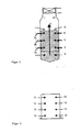
- a combustion chamber 1 of a firing system with a rectangular cross-section four burner levels 2, 3, 4 and 5 are arranged vertically one above the other, the lowest burner level 2 in a first zone 6, the two burner levels 3 and 4 arranged above it in a second zone 7 and the upper one Burner level 5 are in a third zone 8. Above the fourth burner level 5 there are air feeds 9 which are inclined by 10 to 20 ° relative to the horizontal in the direction of the furnace floor.
- the vertical dimensions of the first zone 6 and the second zone 7 are approximately the same size; that of the third zone 8 is about half the size of that of the first two zones 6, 7. Upwards, the third zone 8 is followed by a flue gas space 10, which is delimited at the top by a superheater package 11 and the extent of which is of the same order of magnitude like that of the middle zone 7.
- the upward arrow 12 symbolizes the direction of the flue gas flow in the combustion chamber 1.
- Eight horizontally aligned burners 13 are located in each of the burner levels 2 to 5.
- the eight burners 13 on one level are each arranged four next to one another on two opposite end walls 14 and 15 of the combustion chamber 1.
- the two end walls 14 and 15 form the longer sides of the rectangle in the cross section of the combustion chamber 1.
- the burners 13 of the burner levels 3 and 4 in the second zone 7 are equipped with flue gas return lines 16.
- the superheater package 11 is followed by more, not fully constantly shown flue gas flues 17 leading to a flue gas duct 18.
- the flue gas duct 18 is connected in series in the direction of the flue gas flow to an air preheater 19 and to an electrostatic filter 20.
- a flue gas bypass 21 branches off from the flue gas duct 18.
- the flue gas bypass 21 is a flue gas line which is provided with a metering device 22 and re-opens into the flue gas duct 18 between the air preheater 19 and the electrostatic filter 20.
- a connecting line 23 connects the flue gas duct 18 to the flue gas return lines 16 of the burners 13 of the second zone 7.
- the connecting line 23 there are one metering device 24 and one blower 25 in the direction of the flue gas flow to the burners 13.
- the connecting line 23 is connected in front of the metering device 22 of the flue gas bypass 21 to the flue gas bypass 21 and thus connected to the flue gas duct 18.
- a cold air line 27 provided with a metering device 26 opens into the connecting line 23 between the metering device 24 and the blower 25.
- the cold air line 27 is alternatively provided with an intake port 28 (dash-dotted arrow) or via a second cold air line 29 between an air blower 30 and the air preheater 19 connected to an air line 31.
- the air line 31 leads to the combustion chamber 1 and branches into connections, each provided with metering devices 32, to the burners 13 of the burner levels 2, 3, 4 and 5 and to the air feeds 9.
- the air line 31 has a metering device 33. Between the metering device 33 and the air preheater 19 there is a branch on the air line 31 to an air line 34, which is provided with a metering device 35 and via a water-air cooler 36 behind the metering device 33 of the air line 31 meets the air line 31 again.
- a water line 37 leads via a feed water preheating stage 38 to the water-air cooler 36 and to a further feed water preheating stage 39.
- the total combustion air supplied to the combustion chamber 1 is, depending on the fuel, a factor of 1.05 to 1.3 greater than the stoichiometric value for the combustion of the entire fuel.
- the factor is about 1.05 to 1.10 for the combustion of gas, 1.03 to 1.05 for the combustion of oil and 1.1 to 1.3 for the combustion of coal dust.
- gas with an air factor of 1.10 is used for the entire combustion air supplied to the combustion chamber 1.
- the fuel and combustion air are fed into the combustion chamber 1 in succession in the direction of the flue gas flow in three stages, the entire fuel being fed through the burners 13 of the four burner levels 2, 3, 4 and 5.
- the resulting flue gas flows via the superheater packets 11 through flue gas passages 17 (not shown completely) into the flue gas duct 18.
- the flue gas is passed through the air preheater 19 and through the electrostatic filter 20. 10 to 20% of the flue gas is passed around the air preheater 19 via the metering device 22 in the flue gas bypass 21.
- a further 15% of the flue gas is branched off from the flue gas stream and returned via the metering device 24 and the blower 25 in the connecting line 23 to the flue gas guides 16 of the burners 13 of the second zone 7.
- This recirculated portion of the flue gas is branched off from the flue gas stream in the case of gas firing as well as in oil firing upstream of the air preheater 19.
- the recirculated flue gas between the metering device 24 and the blower 25 via the cold air line 27 is a proportion of 5% of the combustion air set as cold air in the environment with the aid of the metering device 26 temperature or mixed at a temperature of 10 to 50 ° C.
- the temperature of the recirculated flue gas is set to 300 to 360 ° C.
- This cold portion of the combustion air, which is fed to the burners 13 of the reduction zone 7 with the recirculated flue gas, is either freely sucked in from the surroundings via the openings 28 or by the air flow, which is sucked in by the fan 30 and led to the air preheater 19, before Air preheater 19 branched.
- the air flow passed through the air preheater 19 is heated and fed to the combustion chamber 1 as a hot portion of 95% of the combustion air at a temperature of 300 to 360 ° C.
- the temperature of the hot combustion air is essentially determined by the amount of flue gas of 10 to 20% passed around the air preheater 19 and additionally by a partial amount of the hot combustion air which is branched off behind the air preheater 19 and passed through a water-air cooler 36.
- the hot combustion air is divided between the burners 13 of the four burner levels 2, 3, 4 and 5 and the air openings 9.
- the individual proportions are set using the metering devices 33 and are listed in Table 1. It should be taken into account that in the second and third burner levels 3, 4, ie in the second zone, a total of 5% of the combustion air is supplied as cold air with the recirculated flue gas.
- the method C according to the invention described in this example is compared with a method A with a uniform fuel and air supply and a method B with an upper air supply and a uniform flue gas return.
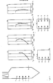
- the temperature profile of method A with a uniform fuel and air supply shows a pronounced temperature maximum.
- OFA combustion chamber
- the entire temperature profile shifts to low temperatures.
- the temperature curve is smoothed compared to the temperature curves of methods A and B by considerably lowering the maximum temperature and slightly increasing the temperature in the first zone 6.
- Example 2 differs from that of Example 1 only in the following points:
- the burner level 5 also belongs to the second zone 7, the extent of which is greater than that of the first zone 6.
- the burner 13 of burner level 5 are also equipped with flue gas recirculation 16.
- Example 1 For the special arrangement of the combustion system described here and the natural gas under consideration, the method D according to the invention (Table 1) of Example 2 leads to a constant, low temperature profile, as shown in FIG. 4, and thus to a reduced NO x emission.
- This method D also has the advantage that it is particularly easy to implement because of the equal distribution of fuel and air in the four burner levels 2 to 5.
- Example 3 two-stage process for the combustion of hard coal dust in a furnace without flue gas recirculation: process G:
- Example 3 for the combustion of hard coal is equipped with an air supply.
- the combustion system differs from example 2 in that only four burners 13 are attached to an end wall 14 in the upper three burner levels 3, 4 and 5 . In the lower burner level 2 there are four burners 13 on each of the two end walls 14, 15.
- coal dust with air with a total air factor of 1.2 is fed to combustion chamber 1.
- the proportion of combustion air supplied in burner levels 2 to 5 is 84%, the proportion quotient in all burner levels 2 to 5 is approximately 0.84 and the air factor is approximately 1.01, i.e. about 17% of the combustion air is supplied per 20% of the fuel.
- the remaining 16% combustion air is supplied through the air inlets 9.
- process G Compared to an even distribution of the fuel over the four burner levels 2 to 5 of process E (see table 2 and FIG. 5), the division of process G according to the invention leads to a substantially more constant temperature profile with a reduced maximum.
- the method G also has the advantage that a simple procedure is made possible by the uniform application of all the burners 13.
- the combustion system of example 4 differs from that of example 3 in that in each of the four burner levels 2, 3, 4 and 5 only four burners 13 are mounted on an end wall 14.
- the device for flue gas recirculation of example 4 differs from that of example 2 in the following point:
- coal dust with air with a total air factor of 1.2 is fed to combustion chamber 1.
- first stage approximately 33% of the fuel is supplied in the first burner level 2 and in the second stage approximately 67% of the fuel is distributed uniformly over the three burner levels 3, 4 and 5.
- the proportion of the combustion air supplied in burner levels 2 to 5 is approximately 85%, with in the first stage in the first burner level 2 approximately 29% of the combustion air (proportion ratio approximately 0.88) and evenly distributed over the three burner levels 3 to 5 in the second stage 56% of the combustion air (share quotient about 0.84) is supplied.
- a third of the recirculated flue gas of 10% is supplied in burner levels 3 to 5 in the second stage.
- the recirculated portion of the flue gas of 10% is branched off behind the electrostatic filter 20.
- the rest of Air supply of approximately 15% of the air takes place through the air supply lines 9.
- the inventive measures of this example are: - increased fuel supply in the first stage and - The flue gas recirculation only in the second stage.
- the pronounced temperature maximum of method E is shifted to lower temperatures by the measures of method F.
- the method H according to the invention also brings about a noticeable lowering of the temperature maximum and an increase in the temperature in the remaining area and thus a further reduction in the NO x emission.
- Example 5 the invention is described using a method for a furnace for the combustion of lignite dust. This is an old system with four burner levels 2, 3, 4 and 5 lying one above the other without supply of air and without recirculation of flue gas (see FIG. 6). The arrangement of the burners 13 corresponds to that of Example 3.
- coal dust with combustion air having a total air factor of 1.2 is fed to combustion chamber 1.
- fuel and combustion air are supplied to the combustion chamber 1 in three stages (cf. Table 3).
- the first burner level 2 is twice 20%, i.e. 40% of the fuel with about 34% of the combustion air
- the second stage which comprises burner levels 3 and 4, 20% of the fuel each with about 17% of the combustion air and in the third stage in the fourth burner level 5 20% of the fuel with about 33% of the combustion air.
- the temperature profile of the flue gas in the combustion chamber of this method J according to the invention calculated according to the furnace zone model is shown in FIG. 6 in addition to the temperature profile of method I with uniform fuel and air input.
- Example 5 Since hard lignite is used as fuel in Example 5, the flue gas temperatures in the corresponding processes are lower than those in Examples 3 and 4, in which hard coal is used.
Landscapes
- Engineering & Computer Science (AREA)
- Chemical & Material Sciences (AREA)
- Combustion & Propulsion (AREA)
- Mechanical Engineering (AREA)
- General Engineering & Computer Science (AREA)
Applications Claiming Priority (2)
| Application Number | Priority Date | Filing Date | Title |
|---|---|---|---|
| DE3825291A DE3825291A1 (de) | 1988-07-26 | 1988-07-26 | Verfahren und feuerungsanlage zur verbrennung fossiler brennstoffe unter reduzierter bildung von stickoxiden |
| DE3825291 | 1988-07-26 |
Publications (2)
| Publication Number | Publication Date |
|---|---|
| EP0352470A2 true EP0352470A2 (fr) | 1990-01-31 |
| EP0352470A3 EP0352470A3 (fr) | 1991-09-25 |
Family
ID=6359533
Family Applications (1)
| Application Number | Title | Priority Date | Filing Date |
|---|---|---|---|
| EP19890111189 Withdrawn EP0352470A3 (fr) | 1988-07-26 | 1989-06-20 | Procédé et installation de combustion pour brûler des combustibles fossiles à formation réduite d'oxides nitriques |
Country Status (2)
| Country | Link |
|---|---|
| EP (1) | EP0352470A3 (fr) |
| DE (1) | DE3825291A1 (fr) |
Cited By (2)
| Publication number | Priority date | Publication date | Assignee | Title |
|---|---|---|---|---|
| FR2679980A1 (fr) * | 1991-08-02 | 1993-02-05 | Stein Industrie | Dispositif de chauffe pour les chaudieres a charbon pulverise utilisant la chauffe tangentielle dans le but de reduire les emissions d'oxydes d'azote. |
| CN112944928A (zh) * | 2021-03-26 | 2021-06-11 | 山东平阴丰源炭素有限责任公司 | 一种低氮焙烧炉及其控制方法 |
Families Citing this family (4)
| Publication number | Priority date | Publication date | Assignee | Title |
|---|---|---|---|---|
| DE19748189A1 (de) * | 1997-10-31 | 1999-05-20 | Infraserv Gmbh & Co Gendorf Kg | Verfahren zur Verminderung nitroser Gase in Verbrennungsanlagen unter gleichzeitiger Energieeinsparung |
| DE19947564A1 (de) * | 1999-10-02 | 2001-04-05 | Kromschroeder Ag G | Verfahren und Einrichtung zum Beheizen eines Ofenraums |
| RU2209369C2 (ru) * | 2001-08-08 | 2003-07-27 | Стенин Валерий Александрович | Способ сжигания органического топлива |
| RU2200276C1 (ru) * | 2002-02-15 | 2003-03-10 | Темиров Назим Юсупович | Устройство для сжигания топлива |
Family Cites Families (14)
| Publication number | Priority date | Publication date | Assignee | Title |
|---|---|---|---|---|
| US4135874A (en) * | 1976-03-31 | 1979-01-23 | Ishikawajima-Harima Jukogyo Kabushiki Kaisha | Two stage combustion furnace |
| CH622081A5 (fr) * | 1977-06-17 | 1981-03-13 | Sulzer Ag | |
| DE2908448C2 (de) * | 1979-03-05 | 1983-04-14 | L. & C. Steinmüller GmbH, 5270 Gummersbach | Brenner zur Verbrennung von stickstoffhaltigen Brennstoffen |
| JPS5623615A (en) * | 1979-08-06 | 1981-03-06 | Babcock Hitachi Kk | Burning method for low nox |
| DE3048201A1 (de) * | 1980-12-20 | 1982-07-08 | L. & C. Steinmüller GmbH, 5270 Gummersbach | "brenner zur verminderung der no(pfeil abwaerts)x(pfeil abwaerts)-emission" |
| CA1204999A (fr) * | 1981-04-08 | 1986-05-27 | Edward J. Campobenedetto | Bruleur pluricombustible a faible emission de nox |
| CA1190093A (fr) * | 1982-08-06 | 1985-07-09 | Ralph D. Winship | Methode pour reprimer les emissions de no.sub.x et de so.sub.x |
| DE3240553A1 (de) * | 1982-11-03 | 1984-05-03 | Kurt Dipl.-Ing. 6380 Bad Homburg Bojak | Umweltfreundliche feuerung fuer kohle-brennstoffe vorzugsweise fuer dampfkessel |
| DE3327597A1 (de) * | 1983-07-30 | 1985-02-07 | Deutsche Babcock Werke AG, 4200 Oberhausen | Verfahren und brenner zum verbrennen von fluessigen oder gasfoermigen brennstoffen unter verminderter bildung von nox |
| DE3403981A1 (de) * | 1984-02-04 | 1985-08-14 | Deutsche Babcock Werke AG, 4200 Oberhausen | Verfahren und vorrichtung zum betreiben einer feuerung unter verminderter bildung von stickoxiden |
| DE3413564A1 (de) * | 1984-04-11 | 1985-10-24 | Deutsche Babcock Werke AG, 4200 Oberhausen | Verfahren und vorrichtung zur verminderung des ausstosses von stickoxiden |
| DE3501189A1 (de) * | 1985-01-16 | 1986-07-17 | Henkel KGaA, 4000 Düsseldorf | Verfahren und anlage zur reduzierung des no(pfeil abwaerts)x(pfeil abwaerts)-gehaltes von mittels fossiler brennstoffe beheizten grossfeuerungsanlagen |
| DE3541987A1 (de) * | 1985-11-28 | 1987-06-04 | Sonvico Ag Ing Bureau | Brenner fuer fluessige und/oder gasfoermige brennstoffe |
| DE3621347A1 (de) * | 1986-06-26 | 1988-01-14 | Henkel Kgaa | Verfahren und anlage zur verminderung des no(pfeil abwaerts)x(pfeil abwaerts)-gehaltes im rauchgas bei kohlenstaubbefeuerten dampferzeugern mit trockenentaschung |
-
1988
- 1988-07-26 DE DE3825291A patent/DE3825291A1/de not_active Withdrawn
-
1989
- 1989-06-20 EP EP19890111189 patent/EP0352470A3/fr not_active Withdrawn
Cited By (2)
| Publication number | Priority date | Publication date | Assignee | Title |
|---|---|---|---|---|
| FR2679980A1 (fr) * | 1991-08-02 | 1993-02-05 | Stein Industrie | Dispositif de chauffe pour les chaudieres a charbon pulverise utilisant la chauffe tangentielle dans le but de reduire les emissions d'oxydes d'azote. |
| CN112944928A (zh) * | 2021-03-26 | 2021-06-11 | 山东平阴丰源炭素有限责任公司 | 一种低氮焙烧炉及其控制方法 |
Also Published As
| Publication number | Publication date |
|---|---|
| DE3825291A1 (de) | 1990-02-01 |
| EP0352470A3 (fr) | 1991-09-25 |
Similar Documents
| Publication | Publication Date | Title |
|---|---|---|
| DE60011541T2 (de) | Verfahren und Vorrichtung zur NOx Reduktion | |
| DE2615369C3 (de) | Verfahren zur Rauchgaskonditionierung in Abfallverbrennungsanlagen mit Wärmeverwertung, insbesondere für kommunalen und industriellen Müll, und Vorrichtung zur Durchführung des Verfahrens | |
| EP0498014B2 (fr) | Procédé pour l'admission d'air de combustion et installation de chauffage | |
| DE69107857T2 (de) | Feuerungssystem mit mehrfachbrennern und mit tangentialer luftzufuhr konzentrisch zum zentralteil des feuerraumes. | |
| DE69315113T2 (de) | Verfahren zur mit Sauerstoff angereicherten Verbrennung | |
| EP0254036A2 (fr) | Procédé et installation pour la réduction de NOx contenu dans les fumées des générateurs de vapeur brûlant la poussière de charbon avec l'élimination sèche de la cendre | |
| DD158936A5 (de) | Verfahren und vorrichtung zur beheizung eines industriellen ofen | |
| DE2408635B2 (de) | Verfahren zum Verbrennen von gasförmigem oder flüssigen Brennstoff | |
| DE4312820A1 (de) | Verfahren zum Verbrennen von Brennstoffen, insbesondere Abfall | |
| DE2658847A1 (de) | Brennereinrichtung | |
| DE69009686T2 (de) | Verbrennungsverfahren. | |
| EP0854339A1 (fr) | Procédé et installation pour le traitement thermique de charges finement granulées | |
| DE60122829T2 (de) | Müllverbrennungsanlage mit Abgasrückführung | |
| DE2750672A1 (de) | Waermeerzeugungsverfahren und vorrichtung zu seiner durchfuehrung | |
| DE2550196C2 (de) | Verfahren zur vollständigen Verbrennung von Gasen mit schwachem Heizwert sowie Verbrennungskammer zur Durchführung des Verfahrens | |
| DD290042A5 (de) | Verbrennungsverfahren zum einschraenken einer bildung von stickstoffoxiden bei verbrennung und anordnung zum ausfuehren des verfahrens | |
| EP0352470A2 (fr) | Procédé et installation de combustion pour brûler des combustibles fossiles à formation réduite d'oxides nitriques | |
| DE19722070C2 (de) | Verfahren zur NO¶x¶-armen Verbrennung von Steinkohle bei trockenentaschten Dampferzeugern | |
| DE2855766C2 (fr) | ||
| DE69614379T2 (de) | NOx-Verminderung in einem Dampferzeuger mit zirkulierender Wirbelschicht | |
| DE102007047107A1 (de) | Verstärktes Hybrid-Nachverbrennungsluft-System und Verfahren zur NOx-Verringerung in Verbrennungsgasen | |
| DE4401821C2 (de) | Verfahren zum Verbrennen von Stoffen, insbesondere von Müll und Biomassen, und Vorrichtung zur Durchführung des Verfahrens | |
| DE69809502T2 (de) | Brenner für flüssigen und gasförmigen Brennstoff mit niedriger Stickoxidemission | |
| DE69527288T2 (de) | Feuerung mit Brenneranlage und Verbrennungsverfahren mit niedriger Stickstoffoxyderzeugung | |
| DE2410592A1 (de) | Verfahren und vorrichtung zum verbrennen von abgas |
Legal Events
| Date | Code | Title | Description |
|---|---|---|---|
| PUAI | Public reference made under article 153(3) epc to a published international application that has entered the european phase |
Free format text: ORIGINAL CODE: 0009012 |
|
| AK | Designated contracting states |
Kind code of ref document: A2 Designated state(s): DE GR SE |
|
| PUAL | Search report despatched |
Free format text: ORIGINAL CODE: 0009013 |
|
| AK | Designated contracting states |
Kind code of ref document: A3 Designated state(s): DE GR SE |
|
| STAA | Information on the status of an ep patent application or granted ep patent |
Free format text: STATUS: THE APPLICATION IS DEEMED TO BE WITHDRAWN |
|
| 18D | Application deemed to be withdrawn |
Effective date: 19910702 |