EP0352531B1 - Aiguille à tirage - Google Patents
Aiguille à tirage Download PDFInfo
- Publication number
- EP0352531B1 EP0352531B1 EP89112511A EP89112511A EP0352531B1 EP 0352531 B1 EP0352531 B1 EP 0352531B1 EP 89112511 A EP89112511 A EP 89112511A EP 89112511 A EP89112511 A EP 89112511A EP 0352531 B1 EP0352531 B1 EP 0352531B1
- Authority
- EP
- European Patent Office
- Prior art keywords
- segments
- draw
- needle according
- needle
- pull
- Prior art date
- Legal status (The legal status is an assumption and is not a legal conclusion. Google has not performed a legal analysis and makes no representation as to the accuracy of the status listed.)
- Expired - Lifetime
Links
- 229910000831 Steel Inorganic materials 0.000 claims description 7
- 239000010959 steel Substances 0.000 claims description 7
- 230000002093 peripheral effect Effects 0.000 claims description 2
- 230000000717 retained effect Effects 0.000 claims 1
- 239000002184 metal Substances 0.000 description 30
- 210000002105 tongue Anatomy 0.000 description 4
- 239000000463 material Substances 0.000 description 3
- 238000000034 method Methods 0.000 description 3
- 238000003466 welding Methods 0.000 description 3
- 230000006978 adaptation Effects 0.000 description 2
- 241000446313 Lamella Species 0.000 description 1
- 238000004026 adhesive bonding Methods 0.000 description 1
- 230000004323 axial length Effects 0.000 description 1
- 230000015572 biosynthetic process Effects 0.000 description 1
- 230000005489 elastic deformation Effects 0.000 description 1
- 238000003780 insertion Methods 0.000 description 1
- 230000037431 insertion Effects 0.000 description 1
- 238000009413 insulation Methods 0.000 description 1
- 239000004922 lacquer Substances 0.000 description 1
- 238000004519 manufacturing process Methods 0.000 description 1
- 238000007493 shaping process Methods 0.000 description 1
- 238000005476 soldering Methods 0.000 description 1
- 239000007787 solid Substances 0.000 description 1
- 239000007858 starting material Substances 0.000 description 1
Images


Classifications
-
- H—ELECTRICITY
- H02—GENERATION; CONVERSION OR DISTRIBUTION OF ELECTRIC POWER
- H02K—DYNAMO-ELECTRIC MACHINES
- H02K15/00—Processes or apparatus specially adapted for manufacturing, assembling, maintaining or repairing of dynamo-electric machines
- H02K15/06—Embedding prefabricated windings in the machines
- H02K15/062—Windings in slots; Salient pole windings
- H02K15/065—Windings consisting of complete sections, e.g. coils or waves
- H02K15/067—Windings consisting of complete sections, e.g. coils or waves inserted in parallel to the axis of the slots or inter-polar channels
-
- Y—GENERAL TAGGING OF NEW TECHNOLOGICAL DEVELOPMENTS; GENERAL TAGGING OF CROSS-SECTIONAL TECHNOLOGIES SPANNING OVER SEVERAL SECTIONS OF THE IPC; TECHNICAL SUBJECTS COVERED BY FORMER USPC CROSS-REFERENCE ART COLLECTIONS [XRACs] AND DIGESTS
- Y10—TECHNICAL SUBJECTS COVERED BY FORMER USPC
- Y10T—TECHNICAL SUBJECTS COVERED BY FORMER US CLASSIFICATION
- Y10T29/00—Metal working
- Y10T29/49—Method of mechanical manufacture
- Y10T29/49002—Electrical device making
- Y10T29/49009—Dynamoelectric machine
-
- Y—GENERAL TAGGING OF NEW TECHNOLOGICAL DEVELOPMENTS; GENERAL TAGGING OF CROSS-SECTIONAL TECHNOLOGIES SPANNING OVER SEVERAL SECTIONS OF THE IPC; TECHNICAL SUBJECTS COVERED BY FORMER USPC CROSS-REFERENCE ART COLLECTIONS [XRACs] AND DIGESTS
- Y10—TECHNICAL SUBJECTS COVERED BY FORMER USPC
- Y10T—TECHNICAL SUBJECTS COVERED BY FORMER US CLASSIFICATION
- Y10T29/00—Metal working
- Y10T29/53—Means to assemble or disassemble
- Y10T29/5313—Means to assemble electrical device
- Y10T29/53143—Motor or generator
- Y10T29/53161—Motor or generator including deforming means
Definitions
- the invention relates to a pull-in needle, consisting of a strip-shaped core and associated sheet metal lips, for use in a device for pulling coils in stators of electrical machines, in which a plurality of pull-in needles, each individually guided longitudinally on a stator tooth, as a group by a common drive axially are movable through the stator bore.
- Twisted stators the grooves of which are helically coiled over their axial length, have better electrical properties in many applications than stators with axially parallel grooves. So far, however, the coils either had to be inserted by hand into the coiled slots, or flexible tongues were used for this purpose in accordance with DE-PS 26.58.891, which were connected in pairs and also in pairs in a single stator slot.
- the flexibility of these tongues allows on the one hand their elastic deformation in adaptation to a coiled stator groove, on the other hand the flexibility is the cause of the decisive disadvantages of these tongues.
- stator teeth are deformed or bulged unevenly over the length by the coils received between them, so that they wear out very quickly due to strong friction on the sharp-edged stator plates in the region of the bulge and on the spring-apart ends.
- the flexible tongues twist in coiled stator slots and can therefore apply the desired guidance and system lose the edges of the stator teeth.
- the invention is therefore based on the object of providing a pull-in needle which is suitable for pulling in coils both in axially parallel and in helical stator slots and which, during the pulling-in operation in engagement with the stator teeth, is essentially equally rigid with respect to the forces exerted by the coils, like the previously used solid straight pull-in needles, each engaging in two stator slots, but on the other hand flexible enough to be inserted into coiled stator slots.
- the core of the pull-in needle consists of several axially arranged, relatively movable segments.
- the invention is based on the finding that sheet metal lips and several core segments arranged axially next to one another can also functionally interact in order to obtain a drawing needle which is on the one hand flexible and on the other hand very stiff during the drawing-in process in the circumferential direction of the stator laminated core.
- the pull-in needle clasps the head of a stator tooth and engages with its sheet metal lips in the two adjacent stator slots, it does not matter for the rigidity of the pull-in needle in the transverse direction that the core is divided into individual segments.
- Another particular advantage of the pull-in needle according to the invention is that the adaptation to different lengths is very simple. Usually stators with a certain sheet cut are made in several different package heights. In all cases, one can prefabricate the same segments in large numbers and then only need a different number of dimensionally matching segments for the different length of retracting needles or just one additional segment individually adjusted in length.
- a pull-in tool consisting of several pull-in needles should not only be relatively stiff in the working position in engagement with the stator teeth, but also outside of the stator in order to facilitate the insertion of the coils between the pull-in needles and the alignment with the stator teeth.
- the segments are held in mutual contact under pressure by means of a tensioning element which is passed at least through the middle segments.
- the tensioning element such as a threaded pull rod, can, for. B. be anchored by screwing into the rearmost segment and supported with a nut or a screw head on the foremost segment.
- the formation of joints between the segments can be omitted, in particular if they are e.g. B. are threaded on a rod-shaped tensioning element, but this can also be omitted in a particularly simple embodiment, since the individual segments on the z. B. connected by spot welding sheet metal lips are also interconnected.
- the number of segments depends primarily on the curvature of the stator slots, the coiled course of which the retracting needles must follow.
- the sheet metal lips can be formed on a single sheet metal bent around the core. But it can also be used for the two sheet metal lips separate sheets and individually with the core segments z. B. connected by spot welding, soldering or gluing. This last-mentioned embodiment is particularly useful when round steel is used as the starting material for the core segments, which is provided with flats on diametrically opposite sides in such a way that the sheet metal lips extend radially with respect to the central longitudinal axis of the stator bore.
- the flats of the segments are stepped along the side edge of the outer jacket surface are offset, the steps each covering a long side of the sheets.
- the segments may furthermore be expedient to place the segments at their mutually adjacent ends in the circumferential regions adjacent to the sheet metal of the sheet metal lips to smaller cross sections. It is practically insignificant that the sheet metal lips are not supported on the relatively short axial distances in the region of the joints between the segments.
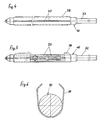
- 1-3 like the pull-in needle described in DE-GM 85 21 173.7, consists of a core 10 made of flattened round material in this case and sheet metal lips 16 and 18 welded or soldered to the flats 12 and 14 on both sides
- the core 10 is divided into several segments 20 arranged axially next to one another, which can be rotated relative to one another and can also be tilted to a limited extent.
- Fig. 2 shows three different designs of bearings between the individual segments. So z. B. in each case a bearing bush 22 can be inserted into an aligned bore in two adjacent segments 20.
- one end face of a segment 20 can also be formed with a projecting pin 24 which engages in a corresponding bore in the adjacent segment.
- Another bearing that can be used alternatively can be a so-called universal bearing, in which either approximately half-shell-shaped spherical bearing surfaces of the adjacent segments 20 are supported on a ball 26 inserted between them, or a hemispherical projection on one segment is supported in a suitable half-shell in the other segment is.
- the segments 20 simply lie flat against one another without exact guidance by a radial bearing or ball joint and execute a sliding movement relative to one another when the pull-in needle is twisted.
- a rod 28 extends as a tensioning element, which is screwed with its threaded rear end into a suitable threaded hole in the rearmost segment 20 and is also on its threaded front End supported via a nut 30 on the outer end face of the foremost segment 20.
- the segments 20 are pressed against one another, and the rigidity of the pull-in needle can thereby be increased without the articulated flexibility being lost.
- the rod 28 holds the segments 20 together, it is not absolutely necessary for all the segments to be connected to the sheet metal lips 16 or 18.
- the sheet metal lips 16 and 18 are preferably not welded, soldered or connected in any other way over the entire length of the segments 20, but only at individual points or in limited areas. In practice, one to three welding spots on the side approximately in the axial center of the segment are normally sufficient to reliably connect it to the sheet metal lip 16 or 18 provided on this side.
- the rearmost segment 20 is formed in one piece with a shaft 32 which is provided with a transverse bore 34.
- the pull-in needle can be brought into engagement with two mutually rotatable, concentric disks, rings or ring segments arranged axially one behind the other, by means of the relative rotation of which a desired inclined position of the pull-in needle can be generated with respect to the axis of rotation.
- a suitable holder can be selected which holds the pull-in needle in the desired inclined position corresponding to the twist of the stator laminate core.
- the rod 28 can also be passed completely through the rearmost segment 20 and z. B. also be supported with a nut, as at the front end, on the outer end face of the rearmost segment.
- the flattened portion 12 of the round steel used for the core 10 is not sunk into the material and the rear edge of the sheet metal lip 16 is ground to match the peripheral surface of the round steel.
- the flattened portion 14 is delimited at its rear end by a step 36, the height of which corresponds to the thickness of the sheet metal lip 18.
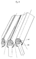
- FIGS. 4-6 differs from that according to FIGS. 1-3 only in that the segments 20 are simply sections of a round steel bar that is otherwise not machined on the outer lateral surface. Accordingly, the two sheet metal lips, designated here by 38, are bent in the region of their abutment on the segments of the core 10 in accordance with the radius of the round steel. It goes without saying that the two sheet metal lips 38 can also consist in one piece of a single sheet metal strip, as is shown in FIG. 7 with the right of the three drawing needles shown.
- FIG. 7 shows the curvature and twisting of the left and middle pull-in needles in particular when they cover one stator tooth of a twisted stator laminated core.
- FIG. 8 shows an exemplary embodiment in which each pull-in needle consists of a helical spring 40 in the core.
- the two sheet metal lips 38 are bent in the region of their abutment on the turns of the helical spring 40 in accordance with their outer diameter.
- a single sheet metal strip, which forms the two sheet metal lips 38, would also be bent.
- a connection between the coil spring 40 and the sheet metal lips 38 is preferably only at individual points.
- a shaft 32 is fixedly connected to the rear end of the coil spring and a head part is fixedly connected to its front end, so that the two ends of the pull-in lamella correspond to those of the previously described exemplary embodiments.
- the coil spring 40 By shaping the coil spring 40, this can also have an outer contour like the core 10 according to FIG. 3, so that the sheet metal lips can be connected to the coil spring 40 on opposite flat surfaces.
Landscapes
- Engineering & Computer Science (AREA)
- Manufacturing & Machinery (AREA)
- Power Engineering (AREA)
- Manufacture Of Motors, Generators (AREA)
- Iron Core Of Rotating Electric Machines (AREA)
Claims (10)
- Aiguille de tirage, constituée d'un noyau (10) en forme de baguette portant des lèvres en tôle (16, 18, 38), pour utilisation dans un dispositif de tirage des bobines à l'intérieur des stators de machines électriques, utilisant plusieurs aiguilles dont chacune coulisse sur une dent du stator et dont l'ensemble se déplace sous l'action d'un entraînement commun axialement à travers l'alésage du stator, caractérisée en ce que le noyau (10) de l'aiguille est constitué de plusieurs segments axiaux juxtaposés (20), mobiles les uns par rapport aux autres.
- Aiguille de tirage selon la revendication 1, caractérisée en ce que des segments voisins (20) sont reliés par des paliers radiaux (22, 24).
- Aiguille de tirage selon la revendication 1, caractérisée en ce que des segments voisins (20) sont reliés par des paliers à surface sphériques (billes 26).
- Aiguille de tirage selon la revendication 1, caractérisée en ce que les segments (20) sont maintenus en appui l'un sur l'autre, avec pression, au moyen d'un organe de tension (28) traversant au moins les segments médians.
- Aiguille de tirage selon une des revendications 1 à 4, caractérisée en ce que les segments (20) sont reliés aux lèvres en tôle (16, 18, 38) au moins en partie seulement dans la zone axiale médiane, par des points de soudure, des joints de brasure ou de colle.
- Aiguille de tirage selon une des revendications 1 à 5, caractérisé en ce que les segments (20) sont constitués de barres rondes en acier avec une surface enveloppe brute ou usinée seulement partiellement.
- Aiguille de tirage selon une des revendications 1 à 6, caractérisée en ce que les extrémités voisines de segments (20) présentent une réduction de section dans les zones de contact avec les lèvres en tôle (16, 18, 38).
- Aiguille de tirage selon une des revendications 1 à 7, caractérisé en ce que le segment (20) le plus en arrière est constitué par une tige de guidage (32), qui peut être amenée en prise avec deux pièces de guidage mobiles relativement l'un par rapport à l'autre.
- Aiguille de tirage selon une des revendications 1 à 8, caractérisé en ce que les segments (20) présentent, sur deux côtés sensiblement diamétralement opposés, des plats (14) le long de chacun desquels repose une tôle, formant lèvre (18), partant d'une bordure latérale constituée par un décrochement (36) de la surface du segment, de manière à servir de recouvrement à un bord longitudinal de la tôle.
- Aiguille de tirage selon la revendication 1, caractérisé en ce que les segments mobiles les uns par rapport aux autres sont constitués par un ressort hélicoïdal (40).
Applications Claiming Priority (2)
| Application Number | Priority Date | Filing Date | Title |
|---|---|---|---|
| DE3825064A DE3825064A1 (de) | 1988-07-23 | 1988-07-23 | Einziehnadel |
| DE3825064 | 1988-07-23 |
Publications (3)
| Publication Number | Publication Date |
|---|---|
| EP0352531A2 EP0352531A2 (fr) | 1990-01-31 |
| EP0352531A3 EP0352531A3 (en) | 1990-06-27 |
| EP0352531B1 true EP0352531B1 (fr) | 1993-04-28 |
Family
ID=6359385
Family Applications (1)
| Application Number | Title | Priority Date | Filing Date |
|---|---|---|---|
| EP89112511A Expired - Lifetime EP0352531B1 (fr) | 1988-07-23 | 1989-07-08 | Aiguille à tirage |
Country Status (5)
| Country | Link |
|---|---|
| US (1) | US4967469A (fr) |
| EP (1) | EP0352531B1 (fr) |
| CA (1) | CA1309577C (fr) |
| DE (2) | DE3825064A1 (fr) |
| ES (1) | ES2042893T3 (fr) |
Families Citing this family (1)
| Publication number | Priority date | Publication date | Assignee | Title |
|---|---|---|---|---|
| DE4222230A1 (de) * | 1992-07-07 | 1994-01-13 | Statomat Spezialmaschinen | Werkzeug zum Aufnehmen und Einziehen von Spulen in Statoren elektrischer Motoren |
Family Cites Families (2)
| Publication number | Priority date | Publication date | Assignee | Title |
|---|---|---|---|---|
| DE3501879C1 (de) * | 1985-01-22 | 1986-07-31 | Franz 7980 Ravensburg Veser | Spuleneinbringleiste fuer Statoren elektrischer Maschinen |
| DE8521173U1 (de) * | 1985-07-23 | 1985-10-03 | Statomat-Globe Maschinenfabrik GmbH, 6369 Niederdorfelden | Einziehnadel |
-
1988
- 1988-07-23 DE DE3825064A patent/DE3825064A1/de not_active Withdrawn
-
1989
- 1989-07-08 EP EP89112511A patent/EP0352531B1/fr not_active Expired - Lifetime
- 1989-07-08 ES ES89112511T patent/ES2042893T3/es not_active Expired - Lifetime
- 1989-07-08 DE DE8989112511T patent/DE58904182D1/de not_active Expired - Fee Related
- 1989-07-21 CA CA000606330A patent/CA1309577C/fr not_active Expired - Fee Related
- 1989-07-21 US US07/382,498 patent/US4967469A/en not_active Expired - Fee Related
Also Published As
| Publication number | Publication date |
|---|---|
| US4967469A (en) | 1990-11-06 |
| EP0352531A2 (fr) | 1990-01-31 |
| EP0352531A3 (en) | 1990-06-27 |
| CA1309577C (fr) | 1992-11-03 |
| DE58904182D1 (de) | 1993-06-03 |
| ES2042893T3 (es) | 1993-12-16 |
| DE3825064A1 (de) | 1990-01-25 |
Similar Documents
| Publication | Publication Date | Title |
|---|---|---|
| DE69515796T2 (de) | Spiralfedern mit zum schweisslosen Verbinden geeigneten Endteilen | |
| EP3345288B1 (fr) | Procédé et dispositif de montage d'une machine électrique | |
| DE10023461B4 (de) | Spulenwickelmaschine und Verfahren zum Wickeln einer Spule aus leitfähigem Draht | |
| EP1604607A1 (fr) | Partie flexible d'un tube d'introduction d'un endoscope et procédé de fabrication | |
| DE2124700A1 (de) | Lineareinstellvorrichtung | |
| DE102019211713A1 (de) | Twistvorrichtung sowie Verfahren für eine Hairpin-Wicklung | |
| CH621020A5 (fr) | ||
| DE19730054C1 (de) | Expansionswerkzeug zum Verformen rohrförmiger Werkstückenden | |
| DE3404975C2 (de) | Stator für einen Elektromotor sowie Verfahren zu dessen Montage | |
| DE69307184T2 (de) | Gewindeklemmschelle | |
| DE102016212382A1 (de) | Verfahren und Adapter zum Wickeln eines Spulenkorbs | |
| DE3027457A1 (de) | Vorrichtung und verfahren zum einfuehren zuvor gewickelter spulen in die nuten eines stators einer drehbaren elektrischen maschine | |
| DE60029718T2 (de) | Anker und Ankerblechzusammenbau für eine elektrische Maschine, insbesondere für einen Gleichstrommotor mit einem Kommutator | |
| EP0352531A2 (fr) | Aiguille à tirage | |
| DE3329290A1 (de) | Bespulungseinrichtung | |
| EP4244956B1 (fr) | Procédé de mise en forme et d'introduction de bobines dans un stator d'une machine électrique tournante | |
| EP0929268B1 (fr) | Appareil dentaire a verin median | |
| DE2309837B2 (de) | Vorrichtung zum Abstreifen von Drahtspulen für elektrische Maschinen von einer Wickelschablone | |
| DE202020102064U1 (de) | Spannbare elektrische Heizvorrichtung | |
| EP4230896A1 (fr) | Ensemble broche pour un dispositif d'entraînement à broche | |
| EP3544161A1 (fr) | Procédé et appareil d'introduction d'une matte enroulé d'arbre dans le rotor ou dans le stator d'une machine électrique, en particulier dans un paquet de tôles statoriques | |
| DE69403652T2 (de) | Spleissleiste fuer isolierte telekommunikationskabel | |
| AT510027B1 (de) | Vorrichtung zum festhalten und kommandierten freigeben eines freizugebenden elements eines raumfahrzeuges | |
| DE69707431T2 (de) | Presswerkzeug | |
| EP0787550A1 (fr) | Foret |
Legal Events
| Date | Code | Title | Description |
|---|---|---|---|
| PUAI | Public reference made under article 153(3) epc to a published international application that has entered the european phase |
Free format text: ORIGINAL CODE: 0009012 |
|
| AK | Designated contracting states |
Kind code of ref document: A2 Designated state(s): DE ES FR GB IT |
|
| PUAL | Search report despatched |
Free format text: ORIGINAL CODE: 0009013 |
|
| AK | Designated contracting states |
Kind code of ref document: A3 Designated state(s): DE ES FR GB IT |
|
| 17P | Request for examination filed |
Effective date: 19901219 |
|
| 17Q | First examination report despatched |
Effective date: 19921005 |
|
| GRAA | (expected) grant |
Free format text: ORIGINAL CODE: 0009210 |
|
| AK | Designated contracting states |
Kind code of ref document: B1 Designated state(s): DE ES FR GB IT |
|
| REF | Corresponds to: |
Ref document number: 58904182 Country of ref document: DE Date of ref document: 19930603 |
|
| ITF | It: translation for a ep patent filed | ||
| ET | Fr: translation filed | ||
| GBT | Gb: translation of ep patent filed (gb section 77(6)(a)/1977) |
Effective date: 19930804 |
|
| REG | Reference to a national code |
Ref country code: ES Ref legal event code: FG2A Ref document number: 2042893 Country of ref document: ES Kind code of ref document: T3 |
|
| PLBE | No opposition filed within time limit |
Free format text: ORIGINAL CODE: 0009261 |
|
| STAA | Information on the status of an ep patent application or granted ep patent |
Free format text: STATUS: NO OPPOSITION FILED WITHIN TIME LIMIT |
|
| 26N | No opposition filed | ||
| PGFP | Annual fee paid to national office [announced via postgrant information from national office to epo] |
Ref country code: GB Payment date: 20010706 Year of fee payment: 13 |
|
| PGFP | Annual fee paid to national office [announced via postgrant information from national office to epo] |
Ref country code: ES Payment date: 20010718 Year of fee payment: 13 |
|
| PGFP | Annual fee paid to national office [announced via postgrant information from national office to epo] |
Ref country code: FR Payment date: 20010730 Year of fee payment: 13 |
|
| PGFP | Annual fee paid to national office [announced via postgrant information from national office to epo] |
Ref country code: DE Payment date: 20010925 Year of fee payment: 13 |
|
| REG | Reference to a national code |
Ref country code: GB Ref legal event code: IF02 |
|
| PG25 | Lapsed in a contracting state [announced via postgrant information from national office to epo] |
Ref country code: GB Free format text: LAPSE BECAUSE OF NON-PAYMENT OF DUE FEES Effective date: 20020708 |
|
| PG25 | Lapsed in a contracting state [announced via postgrant information from national office to epo] |
Ref country code: ES Free format text: LAPSE BECAUSE OF NON-PAYMENT OF DUE FEES Effective date: 20020709 |
|
| PG25 | Lapsed in a contracting state [announced via postgrant information from national office to epo] |
Ref country code: DE Free format text: LAPSE BECAUSE OF NON-PAYMENT OF DUE FEES Effective date: 20030201 |
|
| GBPC | Gb: european patent ceased through non-payment of renewal fee |
Effective date: 20020708 |
|
| PG25 | Lapsed in a contracting state [announced via postgrant information from national office to epo] |
Ref country code: FR Free format text: LAPSE BECAUSE OF NON-PAYMENT OF DUE FEES Effective date: 20030331 |
|
| REG | Reference to a national code |
Ref country code: FR Ref legal event code: ST |
|
| REG | Reference to a national code |
Ref country code: ES Ref legal event code: FD2A Effective date: 20030811 |
|
| PG25 | Lapsed in a contracting state [announced via postgrant information from national office to epo] |
Ref country code: IT Free format text: LAPSE BECAUSE OF NON-PAYMENT OF DUE FEES;WARNING: LAPSES OF ITALIAN PATENTS WITH EFFECTIVE DATE BEFORE 2007 MAY HAVE OCCURRED AT ANY TIME BEFORE 2007. THE CORRECT EFFECTIVE DATE MAY BE DIFFERENT FROM THE ONE RECORDED. Effective date: 20050708 |