EP0352548A2 - Méthode d'enregistrement thermo-magnétique - Google Patents
Méthode d'enregistrement thermo-magnétique Download PDFInfo
- Publication number
- EP0352548A2 EP0352548A2 EP89112754A EP89112754A EP0352548A2 EP 0352548 A2 EP0352548 A2 EP 0352548A2 EP 89112754 A EP89112754 A EP 89112754A EP 89112754 A EP89112754 A EP 89112754A EP 0352548 A2 EP0352548 A2 EP 0352548A2
- Authority
- EP
- European Patent Office
- Prior art keywords
- thin film
- magnetic
- magnetic thin
- film
- temperature
- Prior art date
- Legal status (The legal status is an assumption and is not a legal conclusion. Google has not performed a legal analysis and makes no representation as to the accuracy of the status listed.)
- Granted
Links
Images











Classifications
-
- G—PHYSICS
- G11—INFORMATION STORAGE
- G11B—INFORMATION STORAGE BASED ON RELATIVE MOVEMENT BETWEEN RECORD CARRIER AND TRANSDUCER
- G11B11/00—Recording on or reproducing from the same record carrier wherein for these two operations the methods are covered by different main groups of groups G11B3/00 - G11B7/00 or by different subgroups of group G11B9/00; Record carriers therefor
- G11B11/03—Recording on or reproducing from the same record carrier wherein for these two operations the methods are covered by different main groups of groups G11B3/00 - G11B7/00 or by different subgroups of group G11B9/00; Record carriers therefor using recording by deforming with non-mechanical means, e.g. laser, beam of particles
-
- G—PHYSICS
- G11—INFORMATION STORAGE
- G11B—INFORMATION STORAGE BASED ON RELATIVE MOVEMENT BETWEEN RECORD CARRIER AND TRANSDUCER
- G11B11/00—Recording on or reproducing from the same record carrier wherein for these two operations the methods are covered by different main groups of groups G11B3/00 - G11B7/00 or by different subgroups of group G11B9/00; Record carriers therefor
- G11B11/10—Recording on or reproducing from the same record carrier wherein for these two operations the methods are covered by different main groups of groups G11B3/00 - G11B7/00 or by different subgroups of group G11B9/00; Record carriers therefor using recording by magnetic means or other means for magnetisation or demagnetisation of a record carrier, e.g. light induced spin magnetisation; Demagnetisation by thermal or stress means in the presence or not of an orienting magnetic field
- G11B11/105—Recording on or reproducing from the same record carrier wherein for these two operations the methods are covered by different main groups of groups G11B3/00 - G11B7/00 or by different subgroups of group G11B9/00; Record carriers therefor using recording by magnetic means or other means for magnetisation or demagnetisation of a record carrier, e.g. light induced spin magnetisation; Demagnetisation by thermal or stress means in the presence or not of an orienting magnetic field using a beam of light or a magnetic field for recording by change of magnetisation and a beam of light for reproducing, i.e. magneto-optical, e.g. light-induced thermomagnetic recording, spin magnetisation recording, Kerr or Faraday effect reproducing
- G11B11/10582—Record carriers characterised by the selection of the material or by the structure or form
- G11B11/10586—Record carriers characterised by the selection of the material or by the structure or form characterised by the selection of the material
-
- G—PHYSICS
- G11—INFORMATION STORAGE
- G11B—INFORMATION STORAGE BASED ON RELATIVE MOVEMENT BETWEEN RECORD CARRIER AND TRANSDUCER
- G11B11/00—Recording on or reproducing from the same record carrier wherein for these two operations the methods are covered by different main groups of groups G11B3/00 - G11B7/00 or by different subgroups of group G11B9/00; Record carriers therefor
- G11B11/10—Recording on or reproducing from the same record carrier wherein for these two operations the methods are covered by different main groups of groups G11B3/00 - G11B7/00 or by different subgroups of group G11B9/00; Record carriers therefor using recording by magnetic means or other means for magnetisation or demagnetisation of a record carrier, e.g. light induced spin magnetisation; Demagnetisation by thermal or stress means in the presence or not of an orienting magnetic field
- G11B11/105—Recording on or reproducing from the same record carrier wherein for these two operations the methods are covered by different main groups of groups G11B3/00 - G11B7/00 or by different subgroups of group G11B9/00; Record carriers therefor using recording by magnetic means or other means for magnetisation or demagnetisation of a record carrier, e.g. light induced spin magnetisation; Demagnetisation by thermal or stress means in the presence or not of an orienting magnetic field using a beam of light or a magnetic field for recording by change of magnetisation and a beam of light for reproducing, i.e. magneto-optical, e.g. light-induced thermomagnetic recording, spin magnetisation recording, Kerr or Faraday effect reproducing
- G11B11/10502—Recording on or reproducing from the same record carrier wherein for these two operations the methods are covered by different main groups of groups G11B3/00 - G11B7/00 or by different subgroups of group G11B9/00; Record carriers therefor using recording by magnetic means or other means for magnetisation or demagnetisation of a record carrier, e.g. light induced spin magnetisation; Demagnetisation by thermal or stress means in the presence or not of an orienting magnetic field using a beam of light or a magnetic field for recording by change of magnetisation and a beam of light for reproducing, i.e. magneto-optical, e.g. light-induced thermomagnetic recording, spin magnetisation recording, Kerr or Faraday effect reproducing characterised by the transducing operation to be executed
- G11B11/10504—Recording
- G11B11/10506—Recording by modulating only the light beam of the transducer
-
- G—PHYSICS
- G11—INFORMATION STORAGE
- G11B—INFORMATION STORAGE BASED ON RELATIVE MOVEMENT BETWEEN RECORD CARRIER AND TRANSDUCER
- G11B11/00—Recording on or reproducing from the same record carrier wherein for these two operations the methods are covered by different main groups of groups G11B3/00 - G11B7/00 or by different subgroups of group G11B9/00; Record carriers therefor
- G11B11/10—Recording on or reproducing from the same record carrier wherein for these two operations the methods are covered by different main groups of groups G11B3/00 - G11B7/00 or by different subgroups of group G11B9/00; Record carriers therefor using recording by magnetic means or other means for magnetisation or demagnetisation of a record carrier, e.g. light induced spin magnetisation; Demagnetisation by thermal or stress means in the presence or not of an orienting magnetic field
- G11B11/105—Recording on or reproducing from the same record carrier wherein for these two operations the methods are covered by different main groups of groups G11B3/00 - G11B7/00 or by different subgroups of group G11B9/00; Record carriers therefor using recording by magnetic means or other means for magnetisation or demagnetisation of a record carrier, e.g. light induced spin magnetisation; Demagnetisation by thermal or stress means in the presence or not of an orienting magnetic field using a beam of light or a magnetic field for recording by change of magnetisation and a beam of light for reproducing, i.e. magneto-optical, e.g. light-induced thermomagnetic recording, spin magnetisation recording, Kerr or Faraday effect reproducing
- G11B11/10502—Recording on or reproducing from the same record carrier wherein for these two operations the methods are covered by different main groups of groups G11B3/00 - G11B7/00 or by different subgroups of group G11B9/00; Record carriers therefor using recording by magnetic means or other means for magnetisation or demagnetisation of a record carrier, e.g. light induced spin magnetisation; Demagnetisation by thermal or stress means in the presence or not of an orienting magnetic field using a beam of light or a magnetic field for recording by change of magnetisation and a beam of light for reproducing, i.e. magneto-optical, e.g. light-induced thermomagnetic recording, spin magnetisation recording, Kerr or Faraday effect reproducing characterised by the transducing operation to be executed
- G11B11/10517—Overwriting or erasing
- G11B11/10519—Direct overwriting, i.e. performing erasing and recording using the same transducing means
-
- G—PHYSICS
- G11—INFORMATION STORAGE
- G11B—INFORMATION STORAGE BASED ON RELATIVE MOVEMENT BETWEEN RECORD CARRIER AND TRANSDUCER
- G11B11/00—Recording on or reproducing from the same record carrier wherein for these two operations the methods are covered by different main groups of groups G11B3/00 - G11B7/00 or by different subgroups of group G11B9/00; Record carriers therefor
- G11B11/10—Recording on or reproducing from the same record carrier wherein for these two operations the methods are covered by different main groups of groups G11B3/00 - G11B7/00 or by different subgroups of group G11B9/00; Record carriers therefor using recording by magnetic means or other means for magnetisation or demagnetisation of a record carrier, e.g. light induced spin magnetisation; Demagnetisation by thermal or stress means in the presence or not of an orienting magnetic field
- G11B11/105—Recording on or reproducing from the same record carrier wherein for these two operations the methods are covered by different main groups of groups G11B3/00 - G11B7/00 or by different subgroups of group G11B9/00; Record carriers therefor using recording by magnetic means or other means for magnetisation or demagnetisation of a record carrier, e.g. light induced spin magnetisation; Demagnetisation by thermal or stress means in the presence or not of an orienting magnetic field using a beam of light or a magnetic field for recording by change of magnetisation and a beam of light for reproducing, i.e. magneto-optical, e.g. light-induced thermomagnetic recording, spin magnetisation recording, Kerr or Faraday effect reproducing
- G11B11/10502—Recording on or reproducing from the same record carrier wherein for these two operations the methods are covered by different main groups of groups G11B3/00 - G11B7/00 or by different subgroups of group G11B9/00; Record carriers therefor using recording by magnetic means or other means for magnetisation or demagnetisation of a record carrier, e.g. light induced spin magnetisation; Demagnetisation by thermal or stress means in the presence or not of an orienting magnetic field using a beam of light or a magnetic field for recording by change of magnetisation and a beam of light for reproducing, i.e. magneto-optical, e.g. light-induced thermomagnetic recording, spin magnetisation recording, Kerr or Faraday effect reproducing characterised by the transducing operation to be executed
- G11B11/10517—Overwriting or erasing
- G11B11/10519—Direct overwriting, i.e. performing erasing and recording using the same transducing means
- G11B11/10521—Direct overwriting, i.e. performing erasing and recording using the same transducing means using a single light spot
-
- G—PHYSICS
- G11—INFORMATION STORAGE
- G11B—INFORMATION STORAGE BASED ON RELATIVE MOVEMENT BETWEEN RECORD CARRIER AND TRANSDUCER
- G11B11/00—Recording on or reproducing from the same record carrier wherein for these two operations the methods are covered by different main groups of groups G11B3/00 - G11B7/00 or by different subgroups of group G11B9/00; Record carriers therefor
- G11B11/10—Recording on or reproducing from the same record carrier wherein for these two operations the methods are covered by different main groups of groups G11B3/00 - G11B7/00 or by different subgroups of group G11B9/00; Record carriers therefor using recording by magnetic means or other means for magnetisation or demagnetisation of a record carrier, e.g. light induced spin magnetisation; Demagnetisation by thermal or stress means in the presence or not of an orienting magnetic field
- G11B11/105—Recording on or reproducing from the same record carrier wherein for these two operations the methods are covered by different main groups of groups G11B3/00 - G11B7/00 or by different subgroups of group G11B9/00; Record carriers therefor using recording by magnetic means or other means for magnetisation or demagnetisation of a record carrier, e.g. light induced spin magnetisation; Demagnetisation by thermal or stress means in the presence or not of an orienting magnetic field using a beam of light or a magnetic field for recording by change of magnetisation and a beam of light for reproducing, i.e. magneto-optical, e.g. light-induced thermomagnetic recording, spin magnetisation recording, Kerr or Faraday effect reproducing
- G11B11/10502—Recording on or reproducing from the same record carrier wherein for these two operations the methods are covered by different main groups of groups G11B3/00 - G11B7/00 or by different subgroups of group G11B9/00; Record carriers therefor using recording by magnetic means or other means for magnetisation or demagnetisation of a record carrier, e.g. light induced spin magnetisation; Demagnetisation by thermal or stress means in the presence or not of an orienting magnetic field using a beam of light or a magnetic field for recording by change of magnetisation and a beam of light for reproducing, i.e. magneto-optical, e.g. light-induced thermomagnetic recording, spin magnetisation recording, Kerr or Faraday effect reproducing characterised by the transducing operation to be executed
- G11B11/10523—Initialising
-
- G—PHYSICS
- G11—INFORMATION STORAGE
- G11B—INFORMATION STORAGE BASED ON RELATIVE MOVEMENT BETWEEN RECORD CARRIER AND TRANSDUCER
- G11B11/00—Recording on or reproducing from the same record carrier wherein for these two operations the methods are covered by different main groups of groups G11B3/00 - G11B7/00 or by different subgroups of group G11B9/00; Record carriers therefor
- G11B11/10—Recording on or reproducing from the same record carrier wherein for these two operations the methods are covered by different main groups of groups G11B3/00 - G11B7/00 or by different subgroups of group G11B9/00; Record carriers therefor using recording by magnetic means or other means for magnetisation or demagnetisation of a record carrier, e.g. light induced spin magnetisation; Demagnetisation by thermal or stress means in the presence or not of an orienting magnetic field
- G11B11/105—Recording on or reproducing from the same record carrier wherein for these two operations the methods are covered by different main groups of groups G11B3/00 - G11B7/00 or by different subgroups of group G11B9/00; Record carriers therefor using recording by magnetic means or other means for magnetisation or demagnetisation of a record carrier, e.g. light induced spin magnetisation; Demagnetisation by thermal or stress means in the presence or not of an orienting magnetic field using a beam of light or a magnetic field for recording by change of magnetisation and a beam of light for reproducing, i.e. magneto-optical, e.g. light-induced thermomagnetic recording, spin magnetisation recording, Kerr or Faraday effect reproducing
- G11B11/10502—Recording on or reproducing from the same record carrier wherein for these two operations the methods are covered by different main groups of groups G11B3/00 - G11B7/00 or by different subgroups of group G11B9/00; Record carriers therefor using recording by magnetic means or other means for magnetisation or demagnetisation of a record carrier, e.g. light induced spin magnetisation; Demagnetisation by thermal or stress means in the presence or not of an orienting magnetic field using a beam of light or a magnetic field for recording by change of magnetisation and a beam of light for reproducing, i.e. magneto-optical, e.g. light-induced thermomagnetic recording, spin magnetisation recording, Kerr or Faraday effect reproducing characterised by the transducing operation to be executed
- G11B11/10528—Shaping of magnetic domains, e.g. form, dimensions
Definitions
- the present invention relates to a thermomagnetic recording method such as, for example, a thermomagnetic recording method using irradiation of a laser beam.
- the recording medium having a magnetic thin film formed of a vertically magnetizable film is subjected in advance to initialization, i.e., to a treatment to orient the magnetization in the medium into one direction perpendicular to the plane of the film, and thereafter, magnetic domains having vertical magnetization in the reverse direction to the initial magnetization are formed by heating the medium locally by irradiation of a laser beam or the like, and thereby, the information is recorded thereon as a binarized information bits.
- thermomagnetic recording method when altering recorded information, a process must, prior to the alteration, be performed to erase the recorded information (the process corresponding to the above described initialization), so that a certain time is taken to perform the erasing process, and therefore, recording at a high transmission rate cannot be achieved.
- various real-time recording methods in which overwriting is made possible and thereby the period of time for performing such an independent erasing process can be eliminated.
- hopeful ones for example, are that applies modulated external magnetic field to the medium and that uses two heads, an erasing head as well as a recording head.
- the recording is performed as disclosed, for example, in Japanese Laid-open Patent Publication No. 60-48806 by applying a magnetic field with the polarity corresponding to the state of an input digital signal current to a recording medium, which is provided thereon with an amorphous ferrimagnetic thin film having an axis of easy magnetization perpendicular to the film plane, at its region irradiated by a temperature raising beam.
- thermomagnetic recording methods intended to solve these problems in Japanese Patent Application Nos. 61-194961 and 61-194962 (corresponding to U. S. Patent Application Serial No. 87,440, filed August 20, 1987, and European Patent Application laid open under the number of EP-A-257 530).
- thermomagnetic methods proposed in these applications are such that use a thermomagnetic recording medium provided with a first and a second laminated structure of rare earth-transition metal magnetic thin films and switch and modulate, in accordance with information to be recorded, for example, of "0" and "1", a first heating condition to heat the medium to a first temperature T1 which is virtually above the Curie temperature T C1 of the first magnetic thin film and not reversing the sub-latice magnetization in the second magnetic thin film and a second heating condition to heat the same to a second temperature T2 which is above the temperature T C1 and sufficient to reverse the sub-lattice magnetization in the second magnetic thin film, with the medium applied with a required first external magnetic field, so that, in the cooling stage, the direction of sub-lattice magnetization in the first magnetic thin film is brought into agreement with the direction of the sub-lattice magnetization in the second magnetic thin film by virtue of first and second exchange coupling force, whereby recorded bits (magnetic domains), for example, of "0" and
- thermomagnetic recording method according to Japanese Patent Application No. 61-194961 will be described below.
- the recording of information, for example, of "0" and "1" in this recording method is performed, as shown in FIG. 1 which schematically indicates the above described magnetized states of the first and second magnetic thin films 1 and 2 with small arrows relative to temperature T, by providing, at room temperature T R , a state A with the directions of magnetization in both the magnetic thin films 1 and 2 oriented in one direction and a state B with the same oriented in the reverse directions to each other. And these records are obtained by application of the external magnetic field H ex to the medium and heating the same to the first and second temperatures T1 and T2 by laser beam irradiation.
- a laser beam is first impinged on the position in the state A, with the intensity or time of irradiation of the laser beam modulated in accordance with the recording signal, so that the heating temperature T is brought to the first heating temperature T1 virtually above the Curie temperature T C1 of the first magnetic thin film 1 and causing no reversal of magnetization in the second magnetic thin film 2 under the influence of the required external magnetic field H ex .
- the first magnetic thin film 1 exhibits a state C where it loses its magnetization but, when the laminated film of the magnetic thin films 1 and 2, after the heating has been finished, is cooled below the temperature T C1 , magnetization is produced in the first magnetic thin film 1.
- the direction of magnetization in the first magnetic thin film 1 is oriented into the same direction as that of the second magnetic thin film 2. Namely, the state A is produced whereby information, for example, of a "0" is recorded.
- the heating temperature T is brought to the second heating temperature T2 beyond the above described temperature T1 and sufficient to reverse the magnetization in the second magnetic thin film 2 with the external magnetic field H ex applied.
- the first magnetic thin film 1 is subjected to the exchange coupling force from the second magnetic thin film 2, whereby a state E, i.e., a magnetized state opposite to the original, initialized state, is produced but by virtue of a subsidiary external magnetic field H sub applied in the vicinity of room temperature T R , the direction of the second magnetic thin film 2 is reversed, and thereby, a magnetized state B with magnetic domain walls 3 formed between both the magnetic thin films 1 and 2, the state B being only different from the magnetized state A in that the magnetization in the first magnetic thin film 1 has been reversed, is brought about, and thus, recording of information, for example, of a "1" is achieved.
- a state E i.e., a magnetized state opposite to the original, initialized state
- the recording of information of "0" and “1” is achieved by obtaining the state A and state B as described above.
- the light-intensity-modulated overwriting is applicable to both the state A and the state B. More particularly, by having any position of those in the state A and the state B heated to the temperature T1 or T2 past the state C, by virtue of selected temperatures T1 and T2 as described above, the overwrite of the state A or the state B corresponding to the information "0" or "1” can be achieved no matter whether the original state was the state A or the state B.
- the surface between the magnetic thin films 1 and 2 forming the laminated film is under the influence of exchange energy, whereby the magnetic domain walls 3 are formed in the first state B.
- the domain wall energy ⁇ w is expressed as ⁇ w ⁇ 2( ⁇ A1K1 + ⁇ A2K2 ) (1) (A1 and A2, K1 and K2 are exchange constants and perpendicular magnetic anisotropic constants of the first and second magnetic thin films 1 and 2.)
- the condition H W1 > H C1 + H ex (5) must be satisfied.
- the condition H C2 - H W2 > H ex (6) must be satisfied.
- H W1 and H W2 are quantities defined by the expressions (2) and (3), and H C1 and H C2 , M S1 and M S2 , and h1 and h2 respectively are coercive forces, saturation magnetizations, and thicknesses of the first and second magnetic thin films.
- thermomagnetic recording method capable of real-time overwriting.
- thermomagnetic recording method in which recorded bit is stabilized.
- thermomagnetic recording method in which external magnetic field applied to a thermomagnetic recording medium to initialize the same is reduced.
- thermomagnetic recording method in which higher Kerr rotation angle is obtained upon playback.
- the present invention is adapted such that the above described domain wall energy ⁇ W at room temperature is made small and the temperature characteristic of ⁇ W satisfying the above expression (5) is improved to thereby reduce the film thickness of the second magnetic thin film 2 and lower the subsidiary external magnetic field H sub .
- thermomagnetic recording medium 10 as shown in FIG. 2 is prepared.
- the thermomagnetic recording medium 10 is provided thereon with a laminated film 14 made up of first and second magnetic thin films 11 and 12 having perpendicular magnetic anisotropy with a third magnetic thin film 13 having an in-plane magnetic anisotropy or a small amount of perpendicular magnetic anisotropy sandwiched therebetween, these films being magnetically coupled and laminated in turn to the adjoining one.
- the third magnetic thin film 13 is preferred, even if it has perpendicular magnetic anisotropy, to have sufficiently small perpendicular magnetic anisotropy as against the perpendicular magnetic anisotropy of the first and second magnetic thin films 11 and 12, as low as, for example, 1 x 10⁶ erg/cm3 in perpendicular magnetic anisotropy constant.
- recording of information is performed on the recording medium 10 as shown in FIG. 3, in the same way as described with reference to FIG. 1, by heating the laminated film with laser beam irradiation up to the first and second temperatures T1 and T2. More particularly, a first heating condition to raise the temperature to a first temperature T1 virtually above the Curie temperature T C1 of the first magnetic thin film 11 and causing no reversal of the magnetic moment in the second magnetic thin film 12 and a second heating condition to raise the temperature to a second temperature T2 above the Curie temperature T C1 of the first magnetic thin film 11 and sufficient to reverse the magnetic moment in the second magnetic thin film 12 are modulated in accordance with the information signals to be recorded and the heated positions on the medium are cooled down so that the above described state A and state B are obtained there.
- the recording of information is achieved by bringing about certain states of magnetization in the first and second magnetic thin films 11 and 12.
- the domain wall energy ⁇ W between the first and second magnetic thin films 11 and 12 can be controlled and it is thereby made easier to satisfy the above mentioned expressions (2), (3) and (42).
- the states A and B are brought about via the states A - E as shown in FIG. 3, in the same way as described with FIG. 1. That is, the recording of information by the state A in which the first and second magnetic thin films 11 and 12 are magnetized in the same direction and the state B in which they are magnetized in the reverse directions is performed, and at this time, by virtue of existence of the third magnetic thin film 13, the state of formation of the interface domain walls is stabilized, whereby the margin in designing the characteristics of the magnetic thin films are expanded, the domain wall energy is lowered, and the subsidiary external magnetic field required for the transition from the state E to the state B can be decreased.
- thermomagnetic recording medium 10 used in the present invention is formed, as shown in FIG. 2, of a light transmitting substrate 15 of a glass plate, an acrylic plate, or the like provided with a laminated film 14 deposited on one surface thereof, via a transparent dielectric film 16 serving as a protecting film or an interference film, by, for example, continuous sputtering of the first magnetic thin film 11, the third magnetic thin film 13, and the second magnetic thin film 12 in turn, the laminated film being covered with a protection film 17 of a nonmagnetic metallic film or a dielectric film.
- the dielectric film 16 and the protecting film 17 may be omitted.
- the third magnetic thin film 13 has a strong in-plane anisotropic property, and its thickness is arranged to be thin when the in-plane anisotropic property (k3 ⁇ 0) is strong and to be thick when it is weak such that
- curve 31 ( ⁇ ), curve 32 ( ⁇ ) and curve 33 ( ), respectively, are results from actual measurements of (H C1 + H W1 ), (H C2 + H W2 ), and (H C2 - H W2 ), while curve 34 ( ⁇ ) and curve 35 ( ⁇ ) are results calculated from the measurement results.
- FIG. 5 and FIG. 6 show dependence obtained by computer simulation on the thickness h3 of the third magnetic thin film 13, i.e., referring to FIG. 5, curve 42 indicates dependence of (H C2 + H W2 ), curve 43 that of (H C2 - H W2 ), curve 44 that of H C2 , and curve 45 that of H W2 on h3, while curve 50 in FIG.
- the thicknesses h1 and h2 of the first and second magnetic thin films 1 and 2 are arranged to be 600 ⁇ and characteristic values of the first to third magnetic thin films 1 - 3 are arranged to be the values as shown in Table 1.
- Table 1 1st Magnetic Thin Film 2nd Magnetic Thin Film 3rd Magnetic Thin Film A 0.3 x 10 ⁇ 6 (erg/cm) 0.3 x 10 ⁇ 6 (erg/cm) 2 x 10 ⁇ 6 (erg/cm) K 6 x 10⁶ (erg/cm3) 4 x 10⁶ (erg/cm3) -20 x 106 (erg/cm3) M S -40 (emu/cm3) 180 (emu/cm3) 1800 (emu/cm3)
- the minus sign of M S indicates that the first magnetic thin film 11 is a rare earth rich film.
- the composition is selected to correspond to the position where H W2 and hence ⁇ W exhibits a trough at room temperature (point a) in the characteristic of FIG. 4, then, since the temperature characteristics of the perpendicular anisotropy, magnetization, and others with the increase in the temperature differ with the first to third magnetic thin films 11 - 13, it can be expected that ⁇ W deviates from the minimum point relative to the film thickness h3 and moves to the point b or point c in FIG. 4 and the increase of ⁇ W , or at least decrease of ⁇ W , with increase in the temperature becomes gentle. Thus, at the temperature T ⁇ T C1 - ⁇ close to T C1 , it becomes easier to attain H W1 - H C1 > H ex .
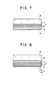
- the first magnetic thin film 11 is formed, as shown in FIG. 7, of two layers of magnetic thin films, first and second component films 111 and 112.
- the first component film 111 is made of a magnetic thin film, for example, of TbFe magnetic film whose Curie temperature T C11 is 130°C and the second component film 112, the layer lying thereunder, is made of Tb(Fe 0.95 Co 0.05 ) whose Curie temperature T C12 is approximately 160°C.
- the third magnetic thin film 13 is made, for example, of FeCo, while the second magnetic thin film 12 is made of a magnetic thin film of GdTbFeCo whose Curie temperature T C2 is about 220°C.
- a transparent dielectric film 16 made of Si3N4 is deposited on a transparent glass substrate 15 provided with guide grooves by the well-known so-called 2P method (Photo Polymerization) as shown in FIG. 8.
- first and second component films 111 and 112 constituting a first magnetic thin film 11, a third magnetic thin film 13, and first and second component films 121 and 122 constituting a second magnetic thin film 12 are deposited in turn. Composition and characteristics of these magnetic thin films are shown in Table 2.
- thermomagnetic recording medium 10 of the described structure it is considered that domain walls are formed in the vicinity of the third magnetic thin film 13 at room temperature.
- the interface domain wall energy ⁇ W on the interface between the second component film 112 of the first magnetic thin film 11 and the first component film 121 of the second magnetic thin film 12 became 1.5 erg/cm2
- the subsidiary external magnetic field H sub necessary for reversing the magnetization in the third magnetic thin film 13 and the first component film 121 of the second magnetic thin film 12 at room temperature became 2.5 kOe.
- the magnetic anisotropy constant K3 - 1.0 x 10⁶ erg/cm3 indicates its in-plane anisotropy.
- ⁇ W becomes 2.8 erg/cm2 and the condition for enabling the overwrite cannot be satisfied unless the first component film 121 of the second magnetic thin film 12 is made as thick as 1000 ⁇ .
- the subsidiary external magnetic field H sub is required to be as high as 3.5 kOe, from which it is known that reduction in the subsidiary external magnetic field can be attained by the embodiment 3.
- the recording characteristics of the disk A provided by using the thermomagnetic recording medium formed according to the embodiment 3 were evaluated and these characteristics are shown in Table 3.
- the measurement results are that obtained from the record made at a linear speed of 10m/sec, and C/N indicates the value at the time of overwriting.
- Table 3 there are also shown a disk B, in which a third magnetic thin film 13 as shown in the above Table 2 is not used and a second magnetic thin film formed of the material of the first component film 121 in a single layer having a thickness of 1000 ⁇ is used, and a disk C, in which the first magnetic thin film is not formed of the first and second component films 111 and 112, but formed of a single layer having a thickness of 550 ⁇ made of the material of the first component film 111.
- the subsidiary external magnetic field H sub can be lowered by providing the third magnetic thin film 13 and the ambient temperature for preserving the record can be raised. Further, it is known that C/N can be improved, with the subsidiary external magnetic field H sub and the recording power kept constant, by forming the first magnetic thin film 11 into a two-layer structure, the layers thereof having different Curie points. Namely, C/N is improved due to the fact that the conditional expression (5a) is completely satisfied and the range of the ambient temperature for stabilized reservation of the record can be expanded due to the fact that the above described expressions (2) and (3) are satisfied more easily.
- a third magnetic thin film 13 of a similarly rare earth rich Tb(Fe 0.95 Co 0.05 ) film having saturation magnetization M S3 200 emu/cm3
- curve 81 ( ⁇ ), curve 82 ( ⁇ ), and curve 83 ( ) are results of actual measurement of (H C1 + H W1 ), (H C2 + H W2 ), and (H C2 - H W2 ), respectively, and curve 84 ( ⁇ ) and curve 85 ( ⁇ ) are results calculated from the measurement results.
- FIG. 10 and FIG. 11 show dependence on the thickness h3 of the third magnetic thin film 13 obtained by computer simulation, namely, in FIG.
- curve 92 shows dependence on h3 of (H C2 + H W2 )
- curve 93 shows that of (H C2 - H W2 )
- curve 94 shows that of H C2
- curve 95 shows that of H W2 .
- the thicknesses h1 and h2 of the first and second magnetic thin films 11 and 12 were set to 600 ⁇ and characteristics of the first to third magnetic thin films 11 - 13 were set to be as shown in Table 4.
- Table 4 First Magnetic Thin Film 11 Second Magnetic Thin Film 12 Third Magnetic Thin Film 13 A 0.3 x 10 ⁇ 6 (erg/cm) 0.3 x 10 ⁇ 6 (erg/cm) 0.05 x 10 ⁇ 6 (erg/cm) K 6 x 10 ⁇ 6 (erg/cm3) 4 x 10 ⁇ 6 (erg/cm3) 0.2 x 10⁶ (erg/cm3) - 1 x 10⁶ (erg/cm3) M S - 40 (emu/cm3) 180 (emu/cm3) - 200 (emu/cm3) H C 18 (kOe) 4 (kOe) 0.2 (kOe)
- a third magnetic thin film 13 having in-plane anisotropy or weak perpendicular anisotropy, so that stabilization of magnetic domain walls is achieved. Thereby, stabilized and positive recording, recording with high C/N, can be achieved.
- the lowering of the subsidiary magnetic field has been achieved by improving characteristics at room temperature, that is, by stabilizing magnetic domain walls and decreasing domain wall energy at room temperature
- an example which adds the above method a function to provide sufficient domain wall energy in the vicinity of the Curie temperature T C1 of the first magnetic thin film, so that the process for the magnetization in the transition metal of the first magnetic thin film 1 to be aligned with the magnetization in the transition metal of the second magnetic thin film 2 described in FIG. 1, that is, the transition from the state C to the state A, or the transition from the state D to the state E, may be positively performed will be described.
- thermomagnetic recording medium 10 as shown in FIG. 2 is used, but the third magnetic thin film 13 is formed of a magnetic thin film of a rare earth rich metallic film, effective magnetic anisotropic constant K of which exhibits a temperature characteristic being convex upward or linear, and the saturation magnetization M S of which at room temperature is 0 to 450 emu/cm3.
- Recording of information is performed on the recording medium 10 as shown in FIG. 3, in the same way as described with reference to FIG. 1, by heating the laminated film with laser beam irradiation up to the first and second temperatures T1 and T2. More particularly, a first heating condition to raise the temperature to a first temperature T1 virtually above the Curie temperature T C1 of the first magnetic thin film 11 and causing no reversal of the magnetic moment in the second magnetic thin film 12 and a second heating condition to raise the temperature to a second temperature T2 above the Curie temperature T C1 of the first magnetic thin film 11 and sufficient to reverse the magnetic moment in the second magnetic thin film 12 are modulated in accordance with the information signals to be recorded and the heated positions on the medium are cooled down so that records by magnetization are obtained there.
- the recording of information is achieved by bringing about certain states of magnetization in the first and second magnetic thin films 11 and 12.
- the domain wall energy ⁇ W between the first and second magnetic thin films 11 and 12 can be controlled and it is thereby made easier to satisfy the above mentioned expressions (5) and (6).
- the states A and B are brought about via the states A - E as shown in FIG. 3, in the same way as described with FIG.1 1. That is, the recording of information by the state A in which the first and second magnetic thin films 11 and 12 are magnetized in the same direction and the state B in which they are magnetized in the reverse directions is performed, and by virtue of existence of the third magnetic thin film 13 at this time, the state of formation of the interface domain walls can be stabilized in the vicinity of room temperature, whereby the margin in designing the characteristics of the magnetic thin films are expanded, the domain wall energy is lowered, and the subsidiary external magnetic field required for the transition from the state E to the state B can be decreased.
- the third magnetic thin film 13 can be selected to be a thin film, for example, of composition of GdFeCo group whose saturation magnetization M S at room temperature is such that 0 ⁇ M S ⁇ 450 emu/cm3, or to be concrete, it is selected to be of composition of Gd x (Fe 1-y Co y ) 1-x , where 0.25 ⁇ x ⁇ 0.40, 0 ⁇ y ⁇ 1.0 (x, y being atomic ratio).
- other rare earth elements such as Dy, Tb, Nd may be added to GdFeCo used as the basic composition.
- K - 1.8 x 10⁷ erg/cm3
- the domain wall energy ⁇ W when a film has a large amount of in-plane anisotropy at room temperature and has a small amount of in-plane anisotropy or an amount of perpendicular anisotropy at high temperatures (in the vicinity of the Curie temperature T C1 ), becomes small at room temperature and becomes large in the vicinity of T C1 .
- the in-plane anisotropy is large at room temperature as described above, but even if a film has a perpendicular anisotropy at room temperature, the domain wall energy ⁇ W can be kept low if the perpendicular anisotropy is of a small value.
- Fig. 14 are shown measurement results of the temperature characteristic of the saturation magnetization M S with the use of a vibrating sample magnetometer (VSM).
- VSM vibrating sample magnetometer
- the curve plotted by is the measurement result of
- RE rich film a rare earth rich film
- TM rich film transition metal rich film
- decreases with increase in the temperature, and hence, even if a composition has in-plane anisotropy at room temperature, it will have sufficiently small amount of in-plane anisotropy or perpendicular anisotropy in the vicinity of T C1 .
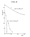
- FIG. 15 shows measurement results of dependence on temperature of the effective magnetic anisotropic constant K of Gd(Fe 0.95 Co 0.05 ) obtained with the use of a magnetic torque meter.
- curve 151 ( ) represents Gd 0.38 (Fe 0.95 Co 0.05 ) 0.62 whose M S at room temperature is approximately 440 emu/cm3
- curve 152 ( ⁇ ) represents Gd 0.32 (Fe 0.95 Co 0.05 ) 0.68 whose M S at room temperature is approximately 280 emu/cm3
- curve 153 ( ⁇ ) represents Gd 0.28 (Fe 0.95 Co 0.05 ) 0.72 whose M S at room temperature is 100 emu/cm3
- curve 154 ( ) represents Gd 0.22 (Fe 0.95 Co 0.05 ) 0.78 whose M S at room temperature is 100 emu/cm3.
- values of K plotted by are 10 times the values indicated along the axis of ordinate of FIG. 15.
- the RE rich film represented by the curve 152 indicates the most preferable characteristics exhibiting in-plane magnetic anisotropy at room temperature but exhibiting perpendicular magnetic anisotropy in the vicinity of the Curie temperature.
- the curve 151 exhibits sufficiently great in-plane magnetic anisotropy at room temperature and exhibits small in-plane magnetic anisotropy in the vicinity of the Curie temperature, which is also a preferable characteristic.
- the curve 153 exhibits perpendicular magnetic anisotropy at room temperature but it is of a small amount and exhibits smaller perpendicular magnetic anisotropy in the vicinity of the Curie temperature, but this composition may sometimes be used if the characteristic at room temperature in question is compensated for by selection of materials and thicknesses of the first and second magnetic thin films 11 and 12, or the like.
- this curve shows a characteristic not only exhibiting perpendicular magnetic anisotropy at room temperature but also exhibiting in-plane magnetic anisotropy in the vicinity of the Curie temperature, a characteristic contrary to that desired.
- FIG. 16 are shown measurement results of the Kerr loop (angle of Kerr rotation ⁇ - magnetic field H curve) for the the magnetic thin film showing the characteristic of the curve 152 in FIG. 15 at various temperatures.
- desired composition of the third magnetic thin film 13, for example, in Gd x (Fe 1-y Co) 1-x is given by 0.25 ⁇ x ⁇ 0.40, 0 ⁇ y ⁇ 1.0, and the value M S is desired to be 0 ⁇ M S ⁇ 450 emu/cm3.
- thermomagnetic recording medium thermomagnetic recording with a semiconductor laser beam in the manner as described with reference to FIG. 3, and reading the record with a similar laser beam by virtue of the Kerr effect were carried out.
- the power P L for writing, for example, a "0" by obtaining the state A via the state C was set to 3.5 mW
- the power P H for writing, for example, a "1” by obtaining the state B via the state D was set to 11 mW
- the power P Read for reading was set to 1.5 mW.
- the external magnetic field H ex was set to 400 Oe
- the subsidiary external magnetic field H sub was set to approximately 3.5 kOe
- the linear speed to approximately 10 m/sec and the bit length to approximately 2.5 ⁇ m.
- a recording medium was made first depositing a dielectric film of Si3N4 on a polycarbonate substrate and then depositing thereon a first magnetic thin film 11 of TbFeCo with a thickness of 400 ⁇ , a third magnetic thin film 13 of an RE rich film (M S ⁇ 600 emu/cm3) of Gd(Fe 0.95 Co 0.05 ) with a thickness of 50 ⁇ , and a second magnetic thin film 12 of (Gd 0.8 Tb 0.2 )(Fe 0.8 Co 0.2 ) with a thickness of 650 ⁇ in turn. First, a 3 MHz signal was recorded therein and then a 3.5 MHz signal was overwritten.
- the 3.0 MHz signal has increased with increase in the Field H ex .
- the following consideration may be made.
- the total magnetization and the magnetization in the transition metal of the first and second magnetic thin films 11 and 12 in the vicinity of the Curie temperature T C1 of the first magnetic thin film and the external magnetic field (recording field) H ex respectively indicated by white arrows end black arrows drawn within the magnetic thin films 11 and 12 and by a white arrow drawn at the right-hand side of the magnetic thin films 11 and 12.
- the intermediate magnetic thin film i.e., the third magnetic thin film 13
- a sufficient exchange force is not obtained in the vicinity of the Curie temperature T C1 of the first magnetic thin film 11, so that such an arrangement becomes unsuitable for light-intensity-modulated overwriting.
- the freedom of selection of characteristics is increased by the arrangement of the third magnetic thin film 13 interposed between the first and second magnetic thin films 11 and 12.
- the third magnetic thin film 13 interposed between the first and second magnetic thin films 11 and 12.
- the temperature T1 at which ⁇ wa and 2M S1 h1H C1 become equal is virtually the temperature at which the magnetization in the first magnetic thin film 11 is oriented in the same direction as the magnetization in the second magnetic thin film 12, namely, the erasing temperature.
- the reproducing layer i.e., the reproducing layer 222 formed of a vertically magnetizable film having a high Curie temperature T C1 , hence a large Kerr rotation angle ⁇ k , will be deposited on a substrate 15, as schematically shown in FIG. 19, and further, the first magnetic thin film 11, the third magnetic thin film 13, and the second magnetic thin film 12 as described in FIG. 3 will be deposited thereon one after another, and thereby the medium will be constructed.
- the previously recorded state is such, as shown in FIG.
- the reproducing layer 222 becomes less effective in performing its function as the reproducing layer.
- it becomes necessary to increase ⁇ wa it contradicts with the provision of the third magnetic thin film 13 having in-plane magnetic anisotropy or small perpendicular magnetic anisotropy at room temperature.
- thermomagnetic recording medium S1 which as shown in a schematic sectional view of FIG. 21 includes a laminated film consisting of a first magnetic thin film 11 formed of a first component film 111 and a second component film 112, each thereof having perpendicular magnetic anisotropy, a second magnetic thin film 12 having perpendicular magnetic anisotropy, and a third magnetic thin film 13 having in-plane magnetic anisotropy or small perpendicular magnetic anisotropy interposed between the first component film 111 of the first magnetic thin film 11 and the second magnetic thin film 12, formed into a laminated structure being magnetically coupled to the adjoining films in turn.
- the Curie temperature T C12 of the second component film 112 is set to be higher than the Curie temperature T C11 of the first component film 111 of the first magnetic thin film 11.
- thermomagnetic recording medium S2 which as shown in a schematic sectional view of FIG. 22 includes a laminated film consisting of a first magnetic thin film 11 formed of a first component film 111 and a second component film 112, each thereof having perpendicular magnetic anisotropy, a second magnetic thin film 12 having perpendicular magnetic anisotropy, and a third magnetic thin film 13 having in-plane magnetic anisotropy or small perpendicular magnetic anisotropy interposed between the first component film 111 of the first magnetic thin film 11 and the second magnetic thin film 12, formed into a laminated structure being magnetically coupled to the adjoining films in turn, further having a magneto-optical reproducing thin film 18 disposed in the front of the first component film 111 of the first magnetic thin film 11 magnetically coupled thereto.
- the Curie temperature T C12 of the second component film 112 is set to be higher than the Curie temperature T C11 of the first component film 111 of the first magnetic thin film 11, and further, the magneto- optical reproducing film 18 is adapted to satisfy 2M SR h R H CR + 2M S11 h11H C11 ⁇ ⁇ wa + 2M S12 h12H C12 (11) (where M SR , M S11 and M S12 ; h R , h11, and h12; H CR , H C11 , and H C12 are saturation magnetization, film thickness, and coercive force of the magneto-optical reproducing thin film 18, first, and second component films 111 and 112, respectively, and ⁇ wa is domain wall energy between the second component film 112 and the second magnetic thin film 12) and having a larger Kerr rotation angle ⁇ K than the first component film 111.
- the Curie temperatures T C11 and T C12 of the first and second component films 111 and 112 of the first magnetic thin film 11 and the Curie temperatures T C2 and T C3 of the second and third magnetic thin films 12 and 13 are selected to be T C11 ⁇ T C12 ⁇ T C3 , T C2 .
- the above described first example of FIG. 21 is characterized in that the first magnetic thin film 11 is formed of the first and second component films 111 and 112, and the Curie temperatures T C11 and T C12 of the component films 111 and 112 are selected to be such that the Curie temperature T C12 of the second component film 112 is higher than the other, i.e., T C11 ⁇ T C12 .
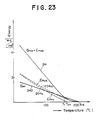
- the effective coercive force energy of the first magnetic thin film 12 of a two-layer structure is given, as shown, for example, in FIG.
- E wa has a linear temperature characteristic as shown by the curve 242, and hence, the difference therebetween becomes large at the temperature lower than the temperature T1, whereby the recorded information bits, i.e., magnetic domains, can be steadily retained, and further, the temperature T1 where both the characteristic curves 242 and 241 intersect can be prevented from greatly varying even when some variations are made in E wa , E HC11 , and E HC12 in the manufacturing process of the thermomagnetic recording media.
- the characteristic of the first magnetic thin film 11 depends only on the characteristic of the second component film 112, so that the effective thickness of the first magnetic thin film 11 is reduced to the small thickness h12 only of the second component film 112, and therefore, expression (8) can also be satisfied.
- the structure used therein is provided with a magneto-optical reproducing thin film 18 having a large Kerr rotation angle ⁇ K added to the above described structure and adapted to satisfy the above described expression (11).
- the first magnetic thin film 11 is prevented from becoming unstable affected by the direction of the magnetization in the magneto-optical reproducing thin film 18 having a high Curie temperature T C1 and the first component film 111 is ensured to form recorded magnetization therein in compliance with the second component film 112 in the vicinity of the Curie temperature T C11 of the first component film 111.
- thermomagnetic recording medium S1 used here is provided, as shown in FIG. 21, by depositing, in turn, first and second component films 111 and 112 constituting a first magnetic thin film 11, a third magnetic thin film 13, and a second magnetic thin film 12, through a dielectric film 16 serving as a protecting film or interference film, over one side of a light transmitting substrate 15 made of a glass plate, acrylic plate, or the like.
- the first and second component films 111 and 112 of the first magnetic thin film 11 are rare earth- transition metal thin films made of a material having rather great perpendicular magnetic anisotropy K U , such as TbFeCo. Both the component films 111 and 112 may be made of either a rare earth rich film or a transition metal rich film but the following conditions must be satisfied.
- condition ⁇ wa > 2M S12 h12H C12 + 2M S12 h12H ex (12) must be satisfied at the temperature right below the Curie temperature T C12 of the second component film 112
- condition ⁇ wb > 2M S11 h11H C11 + 2M S11 h11H ex (13) must be satisfied at the temperature right below T C11 (where ⁇ wb is the domain wall energy density on the interface between the first component film 111 and the second component film 112, and H ex is the external magnetic field, i.e., the external recording magnetic field).
- thermomagnetic recording medium S2 is provided with the above described structure of the thermomagnetic recording medium S1 and additionally a magneto-optical reproducing thin film 18 as shown in FIG. 22. More particularly, also in the thermomagnetic recording medium S2, a light transmitting substrate 15 made of a glass plate, acrylic plate, or the like is used as shown in FIG. 22, and a magneto-optical reproducing thin film 18, first and second component films 111 and 112 constituting a first magnetic thin film 11, a third magnetic thin film 13, and a second magnetic thin film 12, are deposited, in turn, through a dielectric film 16 serving as a protecting film or interference film, over one side of the substrate.
- a light transmitting substrate 15 made of a glass plate, acrylic plate, or the like
- a magneto-optical reproducing thin film 18, first and second component films 111 and 112 constituting a first magnetic thin film 11, a third magnetic thin film 13, and a second magnetic thin film 12 are deposited, in turn, through a dielectric film 16 serving as a
- thermomagnetic recording media S1 and S2 are each achieved by making laminating sputtering in a successive or simultaneous manner through the use, for example, of a magnetron type sputtering apparatus performing, for example, multiple-source sputtering, namely, sputtering from multiple-source targets.
- the third magnetic thin film 13 of each of the thermomagnetic recording media S1 and S2 is desired to have in-plane magnetic anisotropy or lower perpendicular magnetic anisotropy than that of the first and second magnetic thin films 11 and 12, as low as, for example, 1 X 10⁶ erg/cm3 at room temperature and, in addition, be made of a rare earth rich metallic film having the temperature characteristic of its effective magnetic anisotropy constant K being convex upward or linear and the saturation magnetization M S at room temperature being 0 to 450 emu/cm3.
- the second magnetic thin film 12 can be formed of GdTbFeCo having great perpendicular magnetic anisotropy.
- thermomagnetic recording medium S1 will first be described mentioning an embodiment of it.
- thermomagnetic recording medium S1 of the structure as shown in FIG. 21 including the magnetic thin films 111, 112, 13, and 12 having the compositions, magnetic characteristics, and film thicknesses as shown in Table 6 below was prepared.
- Table 6 Thin Film CompoSition Magnetization (emu/cc) Coercive Force (kOe) Curie Temp. (°C) Film Thickness ( ⁇ ) (111) TbFeCo 30 15 170 250 (112) TbFeCo 20 23 210 250 (13) GdFeCo 400 - 235 150 (12) GdTbFeCo 180 3.2 350 580
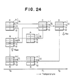
- thermomagnetic recording medium S1 The manner of operations when thermomagnetic recording is made with the above described thermomagnetic recording medium S1 will be described with reference to the drawing of FIG. 24 showing magnetized states.
- the directions of the spin of the transition metal Fe in the films 111, 112, 13, and 12 are indicated by arrows.
- the directions of the external magnetic field H ex and the subsidiary external magnetic field H sub differ with the composition of the second magnetic thin film 12, but the illustrated case is where a transition metal rich film is used for it.
- the first temperature T1 is selected, for example, to be right below the Curie temperature T C11 of the first component film 111
- the second temperature T2 is selected to be above the Curie temperature T C12 of the second component film 112.
- the direction of the spin in the second component film 112 in the process of the medium cooled from that temperature is brought to the state C wherein it is in agreement with that of the second magnetic thin film 12, no matter whether the previous state was A or B, according to the above described expression (13) and the intersection of the curves 241 and 242 in FIG. 23, and in the process cooled down to right below the Curie temperature T C11 of the first component film 111, the direction of the spin in the first component film 111 is brought into agreement with that of the second component film 112 by the arrangement made so that expression (13) is satisfied.
- the state is A or B
- overwriting of the state A is achieved by bringing the medium to the first temperature T1.
- the direction of the spin in the second magnetic thin film 12 is reversed by virtue of the external magnetic field (recording field) H ex , and in the subsequent cooling stage, the state E is brought about wherein the directions of the spin in the first and second component films 111 and 112 of the first magnetic thin film 11 are in agreement with the direction of the spin in the second magnetic thin film 12 according to the conditional expressions (12) and (13).
- the state E is changed by virtue of the subsidiary external magnetic field H sub to the state B wherein the direction of the spin in the second magnetic thin film 12 is reversed.
- the subsidiary external magnetic field H sub is selected to satisfy the following condition. H sub > H C2 + ⁇ wa / 2M S2 h2. (14)
- the domain wall energy is kept sufficiently small in the vicinity of room temperature as indicated by the curve 242, and therefore, the subsidiary external magnetic field H sub in expression (14) can be made sufficiently small.
- thermomagnetic recording medium of a three-layer structure of the structure shown in FIG. 21 but the first magnetic thin film therein is formed of a single film was used.
- Compositions, magnetic characteristics, and film thicknesses of the constituent films in this case are shown in Table 7 below.
- Table 7 Thin Film CompoSition Magnetization (emu/cc) Coercive Force (kOe) Curie Temp. (°C) Film Thickness ( ⁇ ) (11) TbFeCo 30 15 170 500 (13) GdFeCo 400 - 235 125 (12) GdTbFeCo 180 3.2 350 580
- Variations of the erasing temperature T1 for the embodiment 6 and the reference example 2 will be considered referring to FIG. 23 and FIG. 25.
- the first magnetic thin film of two layers having different Curie points it becomes possible, at the time of mass production, to reduce the variations in the temperature T1 against changes in E wa or E HC .
- T C11 - T C12 is 10 - 70°C. This is because, if it is less than 10°C, the effect as described in FIG. 23 is not obtained so much, and, if it exceeds 70°C, i.e., if T C12 becomes too high, it becomes necessary to raise the second temperature T2 and hence to have large recording power.
- Thermomagnetic recording media S2 of the structure as shown in FIG. 22 including the magnetic thin films 18, 111, 112, 13, and 12 having the compositions, magnetic characteristics, and film thicknesses as shown in Table 8 below were prepared.
- Table 8 Thin Film CompoSition Magnetization (emu/cc) Coercive Force (kOe) Curie Temp. (°C) Film Thickness ( ⁇ ) (18) GdFeCo 30 0.4 400 h R (111) TbFeCo 30 15 170 250 (112) TbFeCo 20 23 210 250 (13) GdFeCo 400 - 235 150 (12) GdTbFeCo 180 3.2 350 580
- thermomagnetic recording medium S 2A was prepared by setting the thickness h R of the magneto-optical reproducing thin film 18 to 75 ⁇
- thermomagnetic recording medium S 2B was prepared by setting the thickness h R of the magneto-optical reproducing thin film 18 to 150 ⁇ .
- These media S 2A and S 2B were structured so as to satisfy the above described expression (11).
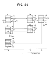
- the manner of operations for thermomagnetic recording using these thermomagnetic recording media S 2A and S 2B is shown in FIG. 26. Referring to FIG. 26, the directions of the spin in the transition metal Fe are shown by arrows drawn in each of the films 185, 111, 112, 13, and 12.
- the first temperature T1 was selected to be the Curie temperature T C11 of the first component film 111 and the second temperature T2 was selected to be above the Curie temperature T C12 of the second component film 112.
- recording of information is made by the states A and B, namely, by the state A wherein the first and the second magnetic thin films 11 and 12 are magnetized in the same direction and the state B wherein they are magnetized in the reverse directions.
- the reproducing thin film 18 is magnetized in the same direction as the first magnetic thin film 11.
- the medium is irradiated, for example, by a laser beam and heated up, for example, to the temperature T1 right below the Curie temperature T C11 of the first component film 111, the direction of the second component film 112 is brought into agreement with that of the second magnetic thin film 12 according to the characteristics shown in FIG. 23. Since, at this time, the Curie temperature T CR of the magneto-optical reproducing thin film 18 is high, either a state C A or a state C B is brought about depending on whether the previous state was the state A or the state B.
- the medium is cooled toward room temperature T R , even if there has been produced the state C B , it is ensured to be changed to the state A during the cooling stage because conditions satisfying expression (11) have been provided, or more particularly, the sum total of the coercive force energy of the magneto-optical reproducing thin film 18 and the coercive force energy of the first component film 111 has been selected to be smaller than the sum total of the domain wall energy ⁇ wa between the second component film 112 and the second magnetic thin film 12 and the coercive force energy of the second component film 112.
- the medium with irradiation for example, of a laser beam up to the second temperature T2 above the Curie temperature T C2 of the second magnetic thin film 12, i.e., above the first and second Curie temperatures T C11 and T C12 , the direction of the spin in the second magnetic thin film 12 is reversed under the influence of the external magnetic field (recording field) H ex , and in the cooling stage of the medium, the state E is brought about wherein the directions of both the first and the second component films 111 and 112 of the first magnetic thin film 11 are in agreement with the direction of the second magnetic thin film 12 according to the above described expressions (12) and (13).
- the state E is changed by the influence of the subsidiary external magnetic field H sub to the state B wherein the spin of the second magnetic thin film 12 is reversed.
- the subsidiary external magnetic field H sub has been selected to satisfy the above described expression (14), and further, the subsidiary external magnetic field H sub can be made sufficiently small the same as described in the embodiment 6.
- thermomagnetic recording medium with a reproducing layer 222 additionally laminated to the three-layer structure described in FIG. 19 was used and thermomagnetic recording media having thin films 222, 11, 13, and 12 of the compositions, magnetic characteristics, and film thicknesses as shown in Table 9 below were prepared.
- Table 9 Thin Film CompoSition Magnetization (emu/cc) Coercive Force (kOe) Curie Temp. (°C) Film Thickness ( ⁇ ) (222) GdFeCo 30 0.4 400 h R (11) TbFeCo 30 15 170 500 (13) GdFeCo 400 -- 235 125 (12) GdTbFeCo 180 3.2 350 580
- the first temperature T1 can be set not to vary so much, i.e., stabilized operation of the device can be achieved, and while C/N (S/N) can be improved, reduction of the subsidiary external magnetic field can also be attained by reduction of the domain wall energy ⁇ w ( ⁇ a ).
- the magneto-optical reproducing thin film 18 having a large Kerr rotation angle ⁇ K enhancement of the reproduced output can be achieved, and further, by the provision of the magneto-optical reproducing thin film 18 having a large Kerr rotation angle ⁇ K , i.e. a high Curie temperature T C1 , improvement for stabilized operation and reduced noise can be achieved.
- the second magnetic thin film 12 is assigned the role to determine the state of recorded magnetic domains and the role to determine the magnitude of the initializing magnetic field (subsidiary external magnetic field). Therefore, when a material having a rather low coercive force H C2 at room temperature is used for the second magnetic thin film 12 in order to lower the initializing magnetic field, the state of the recorded magnetic domains (form, state of magnetization) is disturbed. Hence, a problem is posed that recording noise is increased and it becomes impossible to keep S/N (C/N) sufficiently high.
- thermomagnetic recording medium S as shown in FIG. 28, is used in the present invention, which is formed of, at least, first and second magnetic thin films 11 and 12, each thereof having perpendicular magnetic anisotropy, laminated to each other, the second magnetic thin film 12 being formed by lamination through exchange coupling of its first and second component films 121 and 122.
- thermomagnetic recording medium S3 With the use of such a thermomagnetic recording medium S3, the first heating condition to heat the medium to the first temperature T1 which is virtually in the vicinity of the Curie temperature T C1 of the first magnetic thin film and not causing reversal of the magnetic moment of the second magnetic thin film 12 and the second heating condition to heat the medium to the second temperature T2 which is above the Curie temperature T C1 and sufficient to cause reversal of the magnetic moment of the second magnetic thin film 12 are modulated according to the information signal to be recorded, and adapts such that both of the magnetic moments in the second magnetic thin film 12 during the course the medium is cooled from the first and second heated states are brought into the same state.
- thermomagnetic recording medium S3 is of similar structure as that described above, but the first and second component films 121 and 122 of the second magnetic thin film 12 are made of a material having small perpendicular magnetic anisotropy and a material having relatively great perpendicular magnetic anisotropy.
- thermomagnetic recording medium S3 having magnetic thin films 11, 13, 121, and 122 of compositions, magnetic characteristics, and film thicknesses as shown in Table 10 below and structured as shown in FIG. 28 was prepared.
- Table 10 Thin Film CompoSition Magnetization emu/cc Coercive Force (kOe) Curie Temp. (°C) Magnetic Compensation Temp. (°C) Film Thickness ( ⁇ ) (11) TbFeCo 35 12 170 - 510 (13) GdFeCo 400 - 235 - 125 (121) GdTbFeCo 160 3.9 340 230 300 (122) GdFeCo 150 0.4 400 200 280
- the measured reverse magnetic field, i.e., coercive force H c , of the first and second component films 121 and 122 in the exchange coupled two-layer state was 2.4 kOe.
- the specimen of the above structure will be called the specimen 1.
- a magnetic recording medium was formed of the same constituents as those of the embodiment 8 only having the relative arrangement of the first and second component films of the second magnetic thin film in FIG. 28 reversed. This will be called the specimen 2.
- the second magnetic thin film 12 was formed into a single-layer structure.
- a specimen was prepared with compositions, magnetic characteristics, and thicknesses of the films set to be as shown in Table 11 below.
- Table 11 Thin Film CompoSition Magnetization (emu/cc) Coercive Force (kOe) Curie Temp. (°C) Magnetic Compensation Temp. (°C) Film Thickness ( ⁇ ) (11) TbFeCo 35 12 170 - 520 (13) GdFeCo 400 235 125 (12) GdTbFeCo ⁇ 160 H C2 T C2 ⁇ 230 580
- thermomagnetic recording medium was prepared in the above described arrangement with the coercive force H C2 of the second magnetic thin film 12 set to 3.9 kOe and its Curie temperature T C2 set to 340 °C, as the specimen 3.
- Another thermomagnetic recording medium was prepared in the same arrangement as above with the coercive force H C2 set to 3.1 kOe and its Curie temperature T C2 set to 350 °C, as the specimen 4.
- Another thermomagnetic recording medium was prepared in the same arrangement as above with the coercive force H C2 set to 2.2 kOe and its Curie temperature T C2 set to 360 °C, as the specimen 5.
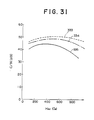
- the measurement results of C/N on the specimens 11 and 12 of the embodiments 8 and 9 according to the present invention are shown by curves 331 and 332 in FIG. 30. Further, similar measurement results on the specimens 3 to 5 according to the reference example 3 are shown by curves 333 to 335 in FIG. 31.
- the noise is produced from unevenness of the shapes of the recorded magnetic domains and unevenness from bit to bit of the state of subdivided structures of the recorded magnetic domains. If ideally recorded magnetic domains are to be shown, they may, for example become uniform circles as in FIG. 32A. against this, FIG. 5B and FIG. 5C show the noise-producing unevenly shaped magnetic domains and subdivided magnetic domains, respectively.
- the recorded magnetic domains are produced in the formation of information bits, i.e., recording, it depends on various conditions such as the recording power, the coercive force H C , thickness h, magnetization M S , and domain wall energy ⁇ B of the magnetic thin films, and the external magnetic field H ex .
- the second magnetic thin film 12 will be considered. When the same is formed in a single layer, it is required to decrease H C2 for lowering H sub , from which it necessarily follows that the recorded domains as shown in FIG. 32B are easily formed causing the noise.
- H C21R > H C22R and T C21 > T C22 as shown by curves 361 and 362 in FIG. 33. In the case where the film is selected to be as characterized in FIG. 29 and the other being that characterized by H C21R > H C22R and T C21 > T C22 as shown by curves 361 and 362 in FIG. 33. In the case where the film is selected to be as characterized in FIG.
- the magnetic field for reversing magnetization of the second magnetic thin film 12 at room temperature T R is given by the average of H C21 and H C22 , and therefore, lowering of the subsidiary external magnetic field H sub , i.e., the initializing magnetic field of the second magnetic thin film 12 can be achieved.
- the state at the time of recording is virtually the same as that when recording is performed on a single-layer film 12 of the first component film 121.
- the effective H C at the time of recording on the second magnetic thin film 12 becomes large so that the formation of the magnetic domains as shown in FIG. 32B is suppressed and production of the resultant noise is suppressed. Accordingly, the noise resulting from the formation of the magnetic domains as shown in FIG. 32C comes into question.
- its second magnetic thin film 12 may be formed of first and second component films 121 and 122 as shown in FIG. 34.
- the first and second component films 121 and 122 may be formed of magnetic thin films both thereof having perpendicular magnetic anisotropy, temperature characteristics of the coercive forces H C21 and H C22 thereof being as shown by curves 321 and 322 in FIG.
- coercive forces at room temperature H C21R and H C22R of the coercive forces H C21 and H C22 being set to be as H C21R > H C22R and Curie temperatures T C21 and T C22 thereof being set to be as T C21 ⁇ T C22 , and thereby, reduction of recording noise and improvement of reproduction C/N (S/N) can be achieved.
- the arrangement of the second magnetic thin film 12 formed of a two-layer structure may be applied to the medium S2 having a magneto-optical reproducing thin film 15 as described in FIG. 22, and in such ways, various modifications of the embodiment other than those described above can be made.
Landscapes
- Physics & Mathematics (AREA)
- Optics & Photonics (AREA)
- Hard Magnetic Materials (AREA)
- Paints Or Removers (AREA)
- Recording Or Reproducing By Magnetic Means (AREA)
Priority Applications (2)
| Application Number | Priority Date | Filing Date | Title |
|---|---|---|---|
| EP96107608A EP0735531B1 (fr) | 1988-07-13 | 1989-07-12 | Méthode d'enregistrement thermo-magnétique |
| EP98122628A EP0901121B1 (fr) | 1988-07-13 | 1989-07-12 | Méthode d'enregistrement thermo-magnétique |
Applications Claiming Priority (8)
| Application Number | Priority Date | Filing Date | Title |
|---|---|---|---|
| JP174695/88 | 1988-07-13 | ||
| JP63174695A JP2829970B2 (ja) | 1988-07-13 | 1988-07-13 | 熱磁気記録媒体 |
| JP272400/88 | 1988-10-28 | ||
| JP63272400A JP2805070B2 (ja) | 1988-10-28 | 1988-10-28 | 熱磁気記録方法 |
| JP1006454A JP2805787B2 (ja) | 1989-01-13 | 1989-01-13 | 光磁気記録方法 |
| JP6454/89 | 1989-01-13 | ||
| JP6453/89 | 1989-01-13 | ||
| JP1006453A JP2797360B2 (ja) | 1989-01-13 | 1989-01-13 | 光磁気記録方法 |
Related Child Applications (2)
| Application Number | Title | Priority Date | Filing Date |
|---|---|---|---|
| EP96107608A Division EP0735531B1 (fr) | 1988-07-13 | 1989-07-12 | Méthode d'enregistrement thermo-magnétique |
| EP96107608.0 Division-Into | 1996-05-13 |
Publications (3)
| Publication Number | Publication Date |
|---|---|
| EP0352548A2 true EP0352548A2 (fr) | 1990-01-31 |
| EP0352548A3 EP0352548A3 (fr) | 1992-09-02 |
| EP0352548B1 EP0352548B1 (fr) | 1997-01-29 |
Family
ID=27454492
Family Applications (3)
| Application Number | Title | Priority Date | Filing Date |
|---|---|---|---|
| EP98122628A Expired - Lifetime EP0901121B1 (fr) | 1988-07-13 | 1989-07-12 | Méthode d'enregistrement thermo-magnétique |
| EP89112754A Expired - Lifetime EP0352548B1 (fr) | 1988-07-13 | 1989-07-12 | Méthode d'enregistrement thermo-magnétique |
| EP96107608A Expired - Lifetime EP0735531B1 (fr) | 1988-07-13 | 1989-07-12 | Méthode d'enregistrement thermo-magnétique |
Family Applications Before (1)
| Application Number | Title | Priority Date | Filing Date |
|---|---|---|---|
| EP98122628A Expired - Lifetime EP0901121B1 (fr) | 1988-07-13 | 1989-07-12 | Méthode d'enregistrement thermo-magnétique |
Family Applications After (1)
| Application Number | Title | Priority Date | Filing Date |
|---|---|---|---|
| EP96107608A Expired - Lifetime EP0735531B1 (fr) | 1988-07-13 | 1989-07-12 | Méthode d'enregistrement thermo-magnétique |
Country Status (7)
| Country | Link |
|---|---|
| US (1) | US5379275A (fr) |
| EP (3) | EP0901121B1 (fr) |
| KR (1) | KR900002264A (fr) |
| AT (3) | ATE241198T1 (fr) |
| AU (1) | AU626073B2 (fr) |
| CA (1) | CA1326547C (fr) |
| DE (3) | DE68927725T2 (fr) |
Cited By (32)
| Publication number | Priority date | Publication date | Assignee | Title |
|---|---|---|---|---|
| EP0428271A3 (en) * | 1989-11-14 | 1991-12-18 | Mitsubishi Denki Kabushiki Kaisha | Magneto-optical recording medium and apparatus |
| EP0428946A3 (en) * | 1989-11-14 | 1991-12-18 | Mitsubishi Denki Kabushiki Kaisha | Magneto-optic recording medium |
| EP0487847A1 (fr) * | 1990-11-26 | 1992-06-03 | Mitsubishi Denki Kabushiki Kaisha | Milieu d'enregistrement magnéto-optique |
| EP0420587A3 (en) * | 1989-09-25 | 1992-10-28 | Nikon Corporation | Over-write capable magnetooptical recording medium |
| EP0513668A1 (fr) * | 1991-05-16 | 1992-11-19 | Sony Corporation | Support d'enregistrement magnéto-optique |
| US5216663A (en) * | 1988-08-24 | 1993-06-01 | Mitsubishi Denki Kabushiki Kaisha | Magneto-optic recording medium and manufacturing method |
| EP0509836A3 (en) * | 1991-04-17 | 1993-07-14 | Sharp Kabushiki Kaisha | Magneto-optical recording medium |
| EP0522840A3 (en) * | 1991-07-08 | 1993-08-18 | Sharp Kabushiki Kaisha | Magneto-optical recording medium |
| US5258237A (en) * | 1989-11-14 | 1993-11-02 | Mitsubishi Denki Kabushiki Kaisha | Magneto-optic recording medium |
| EP0552957A3 (en) * | 1992-01-21 | 1993-11-10 | Sharp Kk | Magneto-optical recording medium and manufacturing method thereof |
| EP0524745A3 (en) * | 1991-07-08 | 1994-02-02 | Sharp Kk | Magneto-optical recording medium whereon recording is carried out with an overwriting function |
| EP0523944A3 (en) * | 1991-07-16 | 1994-02-16 | Canon Kk | Magneto optical recording medium and method |
| EP0586122A1 (fr) * | 1992-09-02 | 1994-03-09 | Sharp Kabushiki Kaisha | Dispositif de mémoire magnéto-optique |
| EP0586175A1 (fr) * | 1992-08-28 | 1994-03-09 | Canon Kabushiki Kaisha | Support d'enregistrement magnéto-optique et procédés d'enregistrement et de reproduction des informations utilisant ce support d'enregistrement |
| EP0593249A3 (fr) * | 1992-10-16 | 1994-10-12 | Canon Kk | Méthode d'enregistrement d'information magnéto-optique. |
| EP0608134A3 (fr) * | 1993-01-22 | 1995-03-08 | Sharp Kk | Milieu d'enregistrement magnéto-optique. |
| EP0618572A3 (fr) * | 1993-04-02 | 1995-04-05 | Canon Kk | Support d'enregistrement magnéto-optique sur lequel il est possible d'enregistrer des informations en haute densité et procédé de reproduction des informations enrégistrées. |
| EP0652556A3 (fr) * | 1993-11-05 | 1995-10-18 | Canon Kk | Milieu d'enregistrement magnéto-optique permettant la super-résolution et méthode de reproduction d'information utilisant le milieu. |
| US5498485A (en) * | 1992-01-21 | 1996-03-12 | Sharp Kabushiki Kaisha | Magneto-optical recording medium and manufacturing method thereof |
| US5512366A (en) * | 1989-11-14 | 1996-04-30 | Mitsubishi Denki Kabushiki Kaisha | Magneto-optic recording medium and apparatus |
| EP0592199A3 (en) * | 1992-10-06 | 1996-05-15 | Sharp Kk | Magneto-optical recording medium and method of recording and reproducing using same |
| EP0596716A3 (fr) * | 1992-11-06 | 1996-09-11 | Sharp Kk | Support d'enregistrement magnétooptique, méthode d'enregistrement et de reproduction ainsi que tête optique conçue pour ce support d'enregistrement magnétooptique. |
| EP0491337B1 (fr) * | 1990-12-19 | 1996-11-20 | Sony Corporation | Milieu magnéto-optique d'enregistrement |
| US5593791A (en) * | 1992-04-10 | 1997-01-14 | Mitsubishi Denki Kabushiki Kaisha | Magneto-optical recording medium and method of manufacturing the same |
| US5662988A (en) * | 1993-01-22 | 1997-09-02 | Sharp Kabushiki Kaisha | Magneto-optical recording medium |
| US5665467A (en) * | 1993-02-25 | 1997-09-09 | Sharp Kabushiki Kaisha | Magneto-optical recording medium |
| US5719829A (en) * | 1993-03-04 | 1998-02-17 | Canon Kabushiki Kaisha | Magnetooptical recording medium allowing super-resolution, and information reproduction method using the medium |
| US5814418A (en) * | 1994-09-27 | 1998-09-29 | Matsushita Electric Industrial Co., Ltd. | Magneto-optical recording medium and method for reading out information from the same |
| EP0831475A3 (fr) * | 1996-09-20 | 1998-09-30 | Victor Company Of Japan, Ltd. | Milieu d'enregistrement magnéto-optique |
| US5955191A (en) * | 1996-07-30 | 1999-09-21 | Sharp Kabushiki Kaisha | Magneto-optical recording medium and a reproducing method using such a medium |
| US6665235B2 (en) | 1992-11-06 | 2003-12-16 | Sharp Kabushiki Kaisha | Magneto-optical recording medium and recording and reproducing method and optical head designed for the magneto-optical recording medium |
| USRE38501E1 (en) * | 1992-08-28 | 2004-04-20 | Canon Kabushiki Kaisha | Magnetooptical recording medium and information recording and reproducing methods using the recording medium |
Families Citing this family (9)
| Publication number | Priority date | Publication date | Assignee | Title |
|---|---|---|---|---|
| JP3092363B2 (ja) | 1992-12-01 | 2000-09-25 | 松下電器産業株式会社 | 光磁気記録媒体 |
| US5596555A (en) * | 1993-07-29 | 1997-01-21 | Canon Kabushiki Kaisha | Magnetooptical recording medium having magnetic layers that satisfy predetermined coercive force relationships, and recording/reproduction method for the medium |
| JP2809991B2 (ja) | 1994-01-14 | 1998-10-15 | 富士通株式会社 | 光磁気記録媒体及び該媒体に記録された情報の再生方法 |
| CA2142767C (fr) * | 1994-02-21 | 1998-11-17 | Naoki Nishimura | Support d'enregistrement magneto-optique et methode d'enregistrement d'informations utilisant ce support |
| JPH07244876A (ja) * | 1994-03-01 | 1995-09-19 | Sharp Corp | 光磁気記録媒体及び光磁気記録再生方法 |
| JPH09120595A (ja) * | 1995-10-23 | 1997-05-06 | Sharp Corp | 光磁気記録媒体 |
| JP3245704B2 (ja) * | 1996-10-18 | 2002-01-15 | 富士通株式会社 | 光磁気記録媒体及びその製造方法 |
| JP4350312B2 (ja) * | 2001-01-12 | 2009-10-21 | キヤノン株式会社 | 磁壁移動型光磁気記録媒体および情報再生方法 |
| US20020192506A1 (en) | 2001-06-04 | 2002-12-19 | International Business Machines Corporation | `Thermal Spring' magnetic recording media for writing using magnetic and thermal gradients |
Family Cites Families (13)
| Publication number | Priority date | Publication date | Assignee | Title |
|---|---|---|---|---|
| JPS6066349A (ja) * | 1983-09-22 | 1985-04-16 | Agency Of Ind Science & Technol | 光熱磁気記録媒体およびその製造方法 |
| US4794560A (en) * | 1985-09-30 | 1988-12-27 | International Business Machines Corporation | Eraseable self biasing thermal magneto-optic medium |
| JPH0695404B2 (ja) * | 1985-12-27 | 1994-11-24 | ソニー株式会社 | 光磁気記録方法 |
| JPS63316343A (ja) * | 1987-06-18 | 1988-12-23 | Canon Inc | 光磁気記録媒体 |
| ATE172047T1 (de) * | 1986-07-08 | 1998-10-15 | Canon Kk | Magnetoptisches aufzeichnungsmedium mit der möglichkeit des überschreibens mit zwei oder mehr magnetschichten und dieses medium verwendende aufzeichnungsmethode |
| JPS6352354A (ja) * | 1986-08-20 | 1988-03-05 | Sony Corp | 熱磁気記録方法 |
| JPS6352355A (ja) * | 1986-08-20 | 1988-03-05 | Sony Corp | 熱磁気記録方法 |
| CA1322408C (fr) * | 1986-08-20 | 1993-09-21 | Tomiji Tanaka | Methode d'enregistrement thermagnetique utilisant un laser module en puissance pour balayer une structure a deux couches couplees magnetiquement |
| JPH0782674B2 (ja) * | 1986-11-06 | 1995-09-06 | キヤノン株式会社 | 光磁気メモリ用媒体 |
| JPS63249951A (ja) * | 1987-04-03 | 1988-10-17 | Mitsubishi Electric Corp | 光磁気記録情報担体 |
| AU600576B2 (en) * | 1987-04-24 | 1990-08-16 | Sony Corporation | Thermomagnetic recording method applying power modulated laser on a magnetically coupled multi-layer structure of perpendicular anisotropy magnetic film |
| JP2754537B2 (ja) * | 1987-05-18 | 1998-05-20 | 株式会社ニコン | 光磁気記録媒体並びにそれを使用したビット形成方法 |
| JPS63304448A (ja) * | 1987-06-04 | 1988-12-12 | Nippon Telegr & Teleph Corp <Ntt> | 光磁気記録媒体 |
-
1989
- 1989-07-07 CA CA000605018A patent/CA1326547C/fr not_active Expired - Fee Related
- 1989-07-10 AU AU37956/89A patent/AU626073B2/en not_active Ceased
- 1989-07-12 DE DE68927725T patent/DE68927725T2/de not_active Expired - Fee Related
- 1989-07-12 AT AT98122628T patent/ATE241198T1/de not_active IP Right Cessation
- 1989-07-12 EP EP98122628A patent/EP0901121B1/fr not_active Expired - Lifetime
- 1989-07-12 EP EP89112754A patent/EP0352548B1/fr not_active Expired - Lifetime
- 1989-07-12 EP EP96107608A patent/EP0735531B1/fr not_active Expired - Lifetime
- 1989-07-12 AT AT96107608T patent/ATE188801T1/de not_active IP Right Cessation
- 1989-07-12 DE DE68929136T patent/DE68929136T2/de not_active Expired - Fee Related
- 1989-07-12 DE DE68929469T patent/DE68929469T2/de not_active Expired - Fee Related
- 1989-07-12 KR KR1019890009895A patent/KR900002264A/ko not_active Ceased
- 1989-07-12 AT AT89112754T patent/ATE148577T1/de not_active IP Right Cessation
-
1993
- 1993-10-05 US US08/131,854 patent/US5379275A/en not_active Expired - Fee Related
Cited By (53)
| Publication number | Priority date | Publication date | Assignee | Title |
|---|---|---|---|---|
| US5216663A (en) * | 1988-08-24 | 1993-06-01 | Mitsubishi Denki Kabushiki Kaisha | Magneto-optic recording medium and manufacturing method |
| US5638344A (en) * | 1989-08-23 | 1997-06-10 | Mitsubishi Denki Kabushiki Kaisha | Magneto-optic recording and reproducing apparatus |
| EP0420587A3 (en) * | 1989-09-25 | 1992-10-28 | Nikon Corporation | Over-write capable magnetooptical recording medium |
| US5273835A (en) * | 1989-09-25 | 1993-12-28 | Nikon Corporation | Over-write capable magnetooptical recording medium |
| EP0428271A3 (en) * | 1989-11-14 | 1991-12-18 | Mitsubishi Denki Kabushiki Kaisha | Magneto-optical recording medium and apparatus |
| EP0428946A3 (en) * | 1989-11-14 | 1991-12-18 | Mitsubishi Denki Kabushiki Kaisha | Magneto-optic recording medium |
| US5512366A (en) * | 1989-11-14 | 1996-04-30 | Mitsubishi Denki Kabushiki Kaisha | Magneto-optic recording medium and apparatus |
| US5679455A (en) * | 1989-11-14 | 1997-10-21 | Mitsubishi Denki Kabushiki Kaisha | Magneto-optic recording medium and apparatus |
| US5258237A (en) * | 1989-11-14 | 1993-11-02 | Mitsubishi Denki Kabushiki Kaisha | Magneto-optic recording medium |
| EP0487847A1 (fr) * | 1990-11-26 | 1992-06-03 | Mitsubishi Denki Kabushiki Kaisha | Milieu d'enregistrement magnéto-optique |
| EP0750295A3 (fr) * | 1990-11-26 | 1997-01-08 | Mitsubishi Denki Kabushiki Kaisha | Milieu d'enregistrement magnéto-optique |
| EP0491337B1 (fr) * | 1990-12-19 | 1996-11-20 | Sony Corporation | Milieu magnéto-optique d'enregistrement |
| US5707727A (en) * | 1991-04-17 | 1998-01-13 | Sharp Kabushiki Kaisha | Magneto-optical recording medium |
| EP0509836A3 (en) * | 1991-04-17 | 1993-07-14 | Sharp Kabushiki Kaisha | Magneto-optical recording medium |
| US6132862A (en) * | 1991-05-16 | 2000-10-17 | Sony Corporation | Magneto-optical recording medium |
| EP0513668A1 (fr) * | 1991-05-16 | 1992-11-19 | Sony Corporation | Support d'enregistrement magnéto-optique |
| US5595805A (en) * | 1991-07-08 | 1997-01-21 | Sharp Kabushiki Kaisha | Magneto-optical recording medium |
| EP0524745A3 (en) * | 1991-07-08 | 1994-02-02 | Sharp Kk | Magneto-optical recording medium whereon recording is carried out with an overwriting function |
| EP0522840A3 (en) * | 1991-07-08 | 1993-08-18 | Sharp Kabushiki Kaisha | Magneto-optical recording medium |
| EP0523944A3 (en) * | 1991-07-16 | 1994-02-16 | Canon Kk | Magneto optical recording medium and method |
| US5428586A (en) * | 1991-07-16 | 1995-06-27 | Canon Kabushiki Kaisha | Magneto-optical recording method using a magneto-optical recording medium having two or more magnetic layers to allow recording and reproduction to be effected simultaneously and magneto-optical recording medium used in the method |
| US5498485A (en) * | 1992-01-21 | 1996-03-12 | Sharp Kabushiki Kaisha | Magneto-optical recording medium and manufacturing method thereof |
| EP0552957A3 (en) * | 1992-01-21 | 1993-11-10 | Sharp Kk | Magneto-optical recording medium and manufacturing method thereof |
| US5593791A (en) * | 1992-04-10 | 1997-01-14 | Mitsubishi Denki Kabushiki Kaisha | Magneto-optical recording medium and method of manufacturing the same |
| EP0586175A1 (fr) * | 1992-08-28 | 1994-03-09 | Canon Kabushiki Kaisha | Support d'enregistrement magnéto-optique et procédés d'enregistrement et de reproduction des informations utilisant ce support d'enregistrement |
| US5889739A (en) * | 1992-08-28 | 1999-03-30 | Canon Kabushiki Kaisha | Magnetooptical recording medium and information recording and reproducing methods using the recording medium |
| USRE38501E1 (en) * | 1992-08-28 | 2004-04-20 | Canon Kabushiki Kaisha | Magnetooptical recording medium and information recording and reproducing methods using the recording medium |
| US5616428A (en) * | 1992-08-28 | 1997-04-01 | Canon Kabushiki Kaisha | Magnetooptical recording medium and information recording and reproducing methods using the recording medium |
| US5631096A (en) * | 1992-09-02 | 1997-05-20 | Sharp Kabushiki Kaisha | Magneto optical memory device |
| EP0586122A1 (fr) * | 1992-09-02 | 1994-03-09 | Sharp Kabushiki Kaisha | Dispositif de mémoire magnéto-optique |
| EP0592199A3 (en) * | 1992-10-06 | 1996-05-15 | Sharp Kk | Magneto-optical recording medium and method of recording and reproducing using same |
| US5751669A (en) * | 1992-10-16 | 1998-05-12 | Canon Kabushiki Kaisha | Overwritable magnetooptical recording method in which the recording medium is cooled after irradiation |
| EP0593249A3 (fr) * | 1992-10-16 | 1994-10-12 | Canon Kk | Méthode d'enregistrement d'information magnéto-optique. |
| US6483785B1 (en) | 1992-11-06 | 2002-11-19 | Sharp Kk | Magneto-optical recording method using the relation of beam diameter and an aperture of converging lens |
| EP0596716A3 (fr) * | 1992-11-06 | 1996-09-11 | Sharp Kk | Support d'enregistrement magnétooptique, méthode d'enregistrement et de reproduction ainsi que tête optique conçue pour ce support d'enregistrement magnétooptique. |
| US6261707B1 (en) | 1992-11-06 | 2001-07-17 | Sharp Kabushiki Kaisha | Magneto-optical recording medium and recording and reproducing method and optical head designed for the magneto-optical recording medium |
| US6665235B2 (en) | 1992-11-06 | 2003-12-16 | Sharp Kabushiki Kaisha | Magneto-optical recording medium and recording and reproducing method and optical head designed for the magneto-optical recording medium |
| EP0974961A3 (fr) * | 1992-11-06 | 2000-07-05 | Sharp Kabushiki Kaisha | Support d'enregistrement magnétooptique et méthode d'enregistrement et de reproduction et tête optique conçue pour le support d'enregistrement magnétooptique |
| EP0608134A3 (fr) * | 1993-01-22 | 1995-03-08 | Sharp Kk | Milieu d'enregistrement magnéto-optique. |
| US5662988A (en) * | 1993-01-22 | 1997-09-02 | Sharp Kabushiki Kaisha | Magneto-optical recording medium |
| US5665467A (en) * | 1993-02-25 | 1997-09-09 | Sharp Kabushiki Kaisha | Magneto-optical recording medium |
| US5719829A (en) * | 1993-03-04 | 1998-02-17 | Canon Kabushiki Kaisha | Magnetooptical recording medium allowing super-resolution, and information reproduction method using the medium |
| US6027825A (en) * | 1993-04-02 | 2000-02-22 | Canon Kabushiki Kaisha | Magnetooptical recording medium on which high-density information can be recorded and method of reproducing the recorded information |
| US6399174B1 (en) | 1993-04-02 | 2002-06-04 | Canon Kabushiki Kaisha | Magnetooptical recording medium on which high-density information can be recorded and method of reproducing the recorded information |
| US6403148B1 (en) | 1993-04-02 | 2002-06-11 | Canon Kabushiki Kaisha | Magnetooptical recording medium on which high-density information can be recorded and method of reproducing the recorded information |
| EP0618572A3 (fr) * | 1993-04-02 | 1995-04-05 | Canon Kk | Support d'enregistrement magnéto-optique sur lequel il est possible d'enregistrer des informations en haute densité et procédé de reproduction des informations enrégistrées. |
| AU684835B2 (en) * | 1993-11-05 | 1998-01-08 | Canon Kabushiki Kaisha | Magnetooptical recording medium allowing super-resolution, and information reproduction method using the medium |
| EP0652556A3 (fr) * | 1993-11-05 | 1995-10-18 | Canon Kk | Milieu d'enregistrement magnéto-optique permettant la super-résolution et méthode de reproduction d'information utilisant le milieu. |
| US5814418A (en) * | 1994-09-27 | 1998-09-29 | Matsushita Electric Industrial Co., Ltd. | Magneto-optical recording medium and method for reading out information from the same |
| US5955191A (en) * | 1996-07-30 | 1999-09-21 | Sharp Kabushiki Kaisha | Magneto-optical recording medium and a reproducing method using such a medium |
| US5903526A (en) * | 1996-09-20 | 1999-05-11 | Victor Company Of Japan, Ltd. | Magneto-optical recording medium having multiple magnetic layers |
| EP0831475A3 (fr) * | 1996-09-20 | 1998-09-30 | Victor Company Of Japan, Ltd. | Milieu d'enregistrement magnéto-optique |
| KR100268325B1 (ko) * | 1996-09-20 | 2000-10-16 | 슈즈이 다케오 | 광자기 기록 매체 |
Also Published As
| Publication number | Publication date |
|---|---|
| EP0901121A3 (fr) | 2000-12-06 |
| EP0352548B1 (fr) | 1997-01-29 |
| CA1326547C (fr) | 1994-01-25 |
| ATE241198T1 (de) | 2003-06-15 |
| EP0735531A1 (fr) | 1996-10-02 |
| EP0735531B1 (fr) | 2000-01-12 |
| EP0901121B1 (fr) | 2003-05-21 |
| US5379275A (en) | 1995-01-03 |
| AU626073B2 (en) | 1992-07-23 |
| DE68927725D1 (de) | 1997-03-13 |
| KR900002264A (ko) | 1990-02-28 |
| EP0352548A3 (fr) | 1992-09-02 |
| EP0901121A2 (fr) | 1999-03-10 |
| ATE188801T1 (de) | 2000-01-15 |
| DE68929469T2 (de) | 2004-03-18 |
| AU3795689A (en) | 1990-01-18 |
| DE68927725T2 (de) | 1997-08-14 |
| ATE148577T1 (de) | 1997-02-15 |
| DE68929136T2 (de) | 2000-06-21 |
| DE68929136D1 (de) | 2000-02-17 |
| DE68929469D1 (de) | 2003-06-26 |
Similar Documents
| Publication | Publication Date | Title |
|---|---|---|
| EP0901121B1 (fr) | Méthode d'enregistrement thermo-magnétique | |
| JP2910250B2 (ja) | 光磁気記録媒体 | |
| EP0415449A2 (fr) | Méthode de reproduction pour enregistrement magnéto-optique | |
| US5740133A (en) | Magneto-optical recording medium capable of double mask readout | |
| US4882231A (en) | Magneto-optical recording medium | |
| KR100238874B1 (ko) | 광자기기록매체에 있어서의 신호재생방법 | |
| US5420833A (en) | Magneto-optical recording medium having first and second magnetic layers | |
| US5175714A (en) | Method of magneto-optically recording/erasing information and magneto-optical information storage medium including recording and bias layers satisfying certain conditions | |
| JPH0393056A (ja) | 光磁気記録媒体 | |
| CA2067945C (fr) | Support d'enregistrement magneto-optique | |
| EP0428271B1 (fr) | Milieu et appareil d'enregistrement magnéto-optique | |
| US5369629A (en) | Magneto-optical recording method and magneto-optical recording medium | |
| US5736265A (en) | Magneto-optical recording medium and recording method using the same | |
| US5502692A (en) | Method and apparatus for recording, reproducing and overwriting information on or from a magnetooptic disk having three magnetic layers | |
| US5814418A (en) | Magneto-optical recording medium and method for reading out information from the same | |
| EP0376680A2 (fr) | Support d'enregistrement magnéto-optique réinscriptible et méthode d'enregistrement utilisant ce support | |
| JP2829970B2 (ja) | 熱磁気記録媒体 | |
| JP2724003B2 (ja) | 光磁気記録媒体 | |
| JP2805787B2 (ja) | 光磁気記録方法 | |
| JP2910287B2 (ja) | 光磁気記録媒体 | |
| KR100203828B1 (ko) | 직접기록 광자기 기록매체 | |
| JP3162168B2 (ja) | 光磁気記録媒体 | |
| KR100209584B1 (ko) | 광자기 디스크 | |
| JP2797360B2 (ja) | 光磁気記録方法 | |
| JP3395189B2 (ja) | 光磁気記録方法 |
Legal Events
| Date | Code | Title | Description |
|---|---|---|---|
| PUAI | Public reference made under article 153(3) epc to a published international application that has entered the european phase |
Free format text: ORIGINAL CODE: 0009012 |
|
| AK | Designated contracting states |
Kind code of ref document: A2 Designated state(s): AT DE FR GB NL |
|
| 17P | Request for examination filed |
Effective date: 19901220 |
|
| PUAL | Search report despatched |
Free format text: ORIGINAL CODE: 0009013 |
|
| AK | Designated contracting states |
Kind code of ref document: A3 Designated state(s): AT DE FR GB NL |
|
| 17Q | First examination report despatched |
Effective date: 19940516 |
|
| GRAG | Despatch of communication of intention to grant |
Free format text: ORIGINAL CODE: EPIDOS AGRA |
|
| GRAH | Despatch of communication of intention to grant a patent |
Free format text: ORIGINAL CODE: EPIDOS IGRA |
|
| GRAH | Despatch of communication of intention to grant a patent |
Free format text: ORIGINAL CODE: EPIDOS IGRA |
|
| GRAA | (expected) grant |
Free format text: ORIGINAL CODE: 0009210 |
|
| AK | Designated contracting states |
Kind code of ref document: B1 Designated state(s): AT DE FR GB NL |
|
| REF | Corresponds to: |
Ref document number: 148577 Country of ref document: AT Date of ref document: 19970215 Kind code of ref document: T |
|
| XX | Miscellaneous (additional remarks) |
Free format text: TEILANMELDUNG 96107608.0 EINGEREICHT AM 13/05/96. |
|
| REF | Corresponds to: |
Ref document number: 68927725 Country of ref document: DE Date of ref document: 19970313 |
|
| ET | Fr: translation filed | ||
| PLBE | No opposition filed within time limit |
Free format text: ORIGINAL CODE: 0009261 |
|
| STAA | Information on the status of an ep patent application or granted ep patent |
Free format text: STATUS: NO OPPOSITION FILED WITHIN TIME LIMIT |
|
| 26N | No opposition filed | ||
| REG | Reference to a national code |
Ref country code: GB Ref legal event code: IF02 |
|
| PGFP | Annual fee paid to national office [announced via postgrant information from national office to epo] |
Ref country code: NL Payment date: 20050703 Year of fee payment: 17 |
|
| PGFP | Annual fee paid to national office [announced via postgrant information from national office to epo] |
Ref country code: GB Payment date: 20050706 Year of fee payment: 17 |
|
| PGFP | Annual fee paid to national office [announced via postgrant information from national office to epo] |
Ref country code: DE Payment date: 20050707 Year of fee payment: 17 |
|
| PGFP | Annual fee paid to national office [announced via postgrant information from national office to epo] |
Ref country code: FR Payment date: 20050708 Year of fee payment: 17 |
|
| PGFP | Annual fee paid to national office [announced via postgrant information from national office to epo] |
Ref country code: AT Payment date: 20050713 Year of fee payment: 17 |
|
| PG25 | Lapsed in a contracting state [announced via postgrant information from national office to epo] |
Ref country code: AT Free format text: LAPSE BECAUSE OF NON-PAYMENT OF DUE FEES Effective date: 20060712 Ref country code: GB Free format text: LAPSE BECAUSE OF NON-PAYMENT OF DUE FEES Effective date: 20060712 |
|
| PG25 | Lapsed in a contracting state [announced via postgrant information from national office to epo] |
Ref country code: NL Free format text: LAPSE BECAUSE OF NON-PAYMENT OF DUE FEES Effective date: 20070201 Ref country code: DE Free format text: LAPSE BECAUSE OF NON-PAYMENT OF DUE FEES Effective date: 20070201 |
|
| GBPC | Gb: european patent ceased through non-payment of renewal fee |
Effective date: 20060712 |
|
| NLV4 | Nl: lapsed or anulled due to non-payment of the annual fee |
Effective date: 20070201 |
|
| REG | Reference to a national code |
Ref country code: FR Ref legal event code: ST Effective date: 20070330 |
|
| PG25 | Lapsed in a contracting state [announced via postgrant information from national office to epo] |
Ref country code: FR Free format text: LAPSE BECAUSE OF NON-PAYMENT OF DUE FEES Effective date: 20060731 |