EP0352576B1 - Chalumeau à souder - Google Patents
Chalumeau à souder Download PDFInfo
- Publication number
- EP0352576B1 EP0352576B1 EP89113019A EP89113019A EP0352576B1 EP 0352576 B1 EP0352576 B1 EP 0352576B1 EP 89113019 A EP89113019 A EP 89113019A EP 89113019 A EP89113019 A EP 89113019A EP 0352576 B1 EP0352576 B1 EP 0352576B1
- Authority
- EP
- European Patent Office
- Prior art keywords
- welding torch
- housing
- drive
- wire
- wire drive
- Prior art date
- Legal status (The legal status is an assumption and is not a legal conclusion. Google has not performed a legal analysis and makes no representation as to the accuracy of the status listed.)
- Expired - Lifetime
Links
- 238000003466 welding Methods 0.000 title claims abstract description 54
- 238000011144 upstream manufacturing Methods 0.000 claims 1
- 230000008878 coupling Effects 0.000 description 7
- 238000010168 coupling process Methods 0.000 description 7
- 238000005859 coupling reaction Methods 0.000 description 7
- 239000007789 gas Substances 0.000 description 3
- CURLTUGMZLYLDI-UHFFFAOYSA-N Carbon dioxide Chemical compound O=C=O CURLTUGMZLYLDI-UHFFFAOYSA-N 0.000 description 2
- 238000010276 construction Methods 0.000 description 2
- 230000001681 protective effect Effects 0.000 description 2
- 230000002411 adverse Effects 0.000 description 1
- 230000005540 biological transmission Effects 0.000 description 1
- 229910002092 carbon dioxide Inorganic materials 0.000 description 1
- 239000001569 carbon dioxide Substances 0.000 description 1
- 239000002826 coolant Substances 0.000 description 1
- 239000000498 cooling water Substances 0.000 description 1
- 230000001419 dependent effect Effects 0.000 description 1
- 230000005611 electricity Effects 0.000 description 1
- 230000002349 favourable effect Effects 0.000 description 1
- 210000003746 feather Anatomy 0.000 description 1
- 239000011261 inert gas Substances 0.000 description 1
- 230000007257 malfunction Effects 0.000 description 1
Images


Classifications
-
- B—PERFORMING OPERATIONS; TRANSPORTING
- B23—MACHINE TOOLS; METAL-WORKING NOT OTHERWISE PROVIDED FOR
- B23K—SOLDERING OR UNSOLDERING; WELDING; CLADDING OR PLATING BY SOLDERING OR WELDING; CUTTING BY APPLYING HEAT LOCALLY, e.g. FLAME CUTTING; WORKING BY LASER BEAM
- B23K37/00—Auxiliary devices or processes, not specially adapted for a procedure covered by only one of the other main groups of this subclass
- B23K37/006—Safety devices for welding or cutting
-
- B—PERFORMING OPERATIONS; TRANSPORTING
- B23—MACHINE TOOLS; METAL-WORKING NOT OTHERWISE PROVIDED FOR
- B23K—SOLDERING OR UNSOLDERING; WELDING; CLADDING OR PLATING BY SOLDERING OR WELDING; CUTTING BY APPLYING HEAT LOCALLY, e.g. FLAME CUTTING; WORKING BY LASER BEAM
- B23K9/00—Arc welding or cutting
- B23K9/12—Automatic feeding or moving of electrodes or work for spot or seam welding or cutting
- B23K9/133—Means for feeding electrodes, e.g. drums, rolls, motors
- B23K9/1336—Driving means
-
- B—PERFORMING OPERATIONS; TRANSPORTING
- B23—MACHINE TOOLS; METAL-WORKING NOT OTHERWISE PROVIDED FOR
- B23K—SOLDERING OR UNSOLDERING; WELDING; CLADDING OR PLATING BY SOLDERING OR WELDING; CUTTING BY APPLYING HEAT LOCALLY, e.g. FLAME CUTTING; WORKING BY LASER BEAM
- B23K9/00—Arc welding or cutting
- B23K9/24—Features related to electrodes
- B23K9/28—Supporting devices for electrodes
- B23K9/287—Supporting devices for electrode holders
Definitions
- the invention relates to a welding torch with the features in the preamble of the main claim.
- Such a welding torch is known from DE-A1-35 45 505.
- the cut-off protection is arranged behind the wire drive in the wire feed direction.
- the burner tube is connected to the evasive part of the shutdown protection, while its housing and the wire drive form a structural unit and are jointly attached to the hand of a robot.
- the shutdown protection has two functions. On the one hand, it serves as an emergency switch for stopping the welding torch in the event of a collision with the workpiece. On the other hand, it is used as a touch switch for locating the weld path reference points. In both cases, the arrangement of the switch-off protection behind the wire drive has proven to be disadvantageous for the wire guide. When the burner tube is swiveled with the cut-off protection, the wire that is pushed in this section only has to be deflected. This can adversely affect the uniformity of the wire feed.
- the cut-off safeguard is now located in the wire feed direction in front of the wire drive, so that wire deflection can only take place in front of the wire drive, that is to say in the pulling area.
- the welding wire is fed straight behind the wire drive without deflections. This means that there can no longer be any malfunctions in the wire feed.
- the switch-off safeguard itself can be designed differently, a construction in accordance with DE-A1-35 45 505.5 being recommended.
- the movable part of the shutdown protection is connected to the wire drive and the burner tube as well as any additional components, while the shutdown protection or its housing is mounted on the hand of a manipulator.
- the lines for the operating media such as protective gas, cooling medium, electricity, but also the guide for the welding wire, which are supplied from the outside, are connected to the movable part of the cut-off protection or to the parts of the welding torch arranged thereon.
- the lines in question are rigidly laid within the adjoining areas of the wire drive, the burner tube or any additional unit. This arrangement offers a significantly higher line elasticity when the burner evades.
- the bundle of lines does not first have to be connected to a relatively fixed point, such as the cut-off fuse housing or the robot hand, and from there it has to be led to the individual parts of the burner with short cables at risk of kinking. Rather, the lines for corresponding deformations in the hose have a large free length and in addition the hose elasticity, so that they are subjected to evasive movements less than before and have greater durability and operational reliability.
- the welding torch according to the invention is particularly suitable for combination with industrial robots, for which it has further specific advantages.
- the structure of the welding torch allows a reduction in the overall size and the torch weight.
- the welding torch according to the invention can thus also be used on smaller robots.
- the welding torch according to the invention can also be used on simpler manipulators, tool guides or the like Devices.
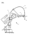
- Fig. 1 shows a six-axis industrial robot (1), on the hand (6) a welding torch (2) is arranged.
- Welding wire (4) is fed to the torch from a roll in a hose (19) which exits to the workpiece at the end of the torch tube (10).
- the arrangement shown is designed for inert gas welding, for example with carbon dioxide.
- the protective gas and other operating resources are also fed to the burner via the hose (19) in a line bundle (27) (cf. FIGS. 2 and 4).
- the welding robot (1) is used for automatic welding, whereby it also automatically searches for and tracks the seam path. If necessary, a welding sensor (25) can intervene in a corrective manner (cf. FIG. 2).
- the welding torch (2) has a wire drive (3) and a cut-off protection (5), the latter serving as an emergency cut-out in the event of a collision with the workpiece and as a signal generator for locating the seam path.
- a torch height control dependent on the welding current is provided for tracking the seam path during welding, possibly in connection with a pendulum movement of the torch.
- the wire drive (3) is designed as a double roller drive. But it can also be any other way, e.g. be designed as a swivel head or four-roller drive.
- the cut-off safeguard (5) is arranged in the wire feed direction (22) in front of the wire drive (3), in particular in front of its drive rollers (23).
- the drive rollers (23) are located approximately at the level of the hand axis (28).
- the cut-off protection (5) is arranged above this robot axis (28).
- the complete wire drive (3) with its motor (11), the gearbox (24), the drive rollers (23) and the other parts, together with the burner tube (10), is on the movable part of the shutdown protection (5), here a switching disc (14 ), stored.
- the housing (8) of the cut-off protection (5) is attached to the flange plate (7) of the robot hand (6).
- the wire drive (3) and the torch tube (10) with the switching disc (14) dodge.
- the welding wire (4) fed through a guide tube (13) is passed through the rigid connection of the burner tube (10) to the wire drive (3) is thus always guided in a straight path from the drive rollers (23) to the outlet at the end of the burner tube.
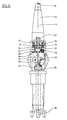
- the cut-off protection (5) has a circular switching disk (14) which is directly or indirectly engaged with a plurality of switching contacts (15), here in the form of microswitches.
- the switching disk (14) is pressed on by springs (17) and lies laterally on the lower edge of the housing (8).
- Rotary locks (16) are also arranged in the housing (8), with the aid of which the switching disk (14) can be aligned and adjusted.
- the switching disk (14) has a collar (29) projecting downward from the housing (8), to which the housing (18) of the wire drive (3) is detachably fastened via a clamping ring (30).
- the two housings (8,18) are arranged one above the other with sufficient freedom of movement.
- the burner tube (10) is fastened to the wire drive (3) in a rapidly replaceable manner by means of a quick-action lock (26).
- the quick-action fastener (26) engages behind the burner tube (10) at corresponding recesses with a fork and presses it resiliently into a receptacle.
- the wire drive (3) and the burner tube (10) thus hang on the switching disc (14).
- the switching disc (14) tipping or axially lifting against its resetting spring force (17) about its pivot point (21).
- one or more of the microswitches (15) which are evenly distributed over the circumference, are opened and emit a corresponding signal to the control of the robot (1).
- the switching disc (14) reacts to deflections of the burner tube (10) in all directions. After discharge the switching disc (14) automatically returns to its starting position.
- the housing (8) of the cut-off safeguard (5) is connected to the flange plate (7) by means of two webs (9) spaced laterally from one another.
- the webs (9) extend from the flange plate (7) upwards to the housing (8).
- connection (12) for the signal line is arranged on the housing (8) of the switch-off safeguard (5), which is relatively stationary relative to the robot hand.
- the power and signal line for the wire drive (3) is led to the relatively movable drive housing.
- the various lines open further up into the line bundle (27).
- the funnel-shaped hose nozzle (20) is also attached to the housing (8).
- the cable bundle (27) itself is clamped only at the upper end of the hose nozzle (20) and is otherwise guided with lateral play and freely through the hose nozzle (20) and the switching disc (14).
- a line connection (31) in the form of a plug-in coupling is arranged in the collar (29) in the area of the connection to the drive housing (18).
- One coupling half is connected to the line bundle (27) and combines the various cables and lines for shielding gas, cooling water with flow and return, etc. and the welding wire guide. It is fixed in the coupling position using a clamping screw (32) and a cone in the collar (29).
- the other coupling half is attached to the drive housing. From here, the individual lines in the drive housing (18) and rigidly laid in the burner tube (10).
- the welding wire (4) is guided between the drive rollers (23) via a guide tube (13) and reaches the burner tube (10) via a second tube of this type.
- the plug-in coupling (31) When the burner tube (10) evades, the plug-in coupling (31) is moved along with the rigidly laid lines. A compensation movement of the lines takes place only above the plug-in coupling (31) in the area up to the upper end of the hose nozzle (20) and in the subsequent hose (19). Due to the large free deformation length, the cables can easily accommodate the evasive movement elastically.
- a welding sensor (25) is fastened with its housing (33). It has a sensor tube (34) which is rotatably mounted and can be moved via a drive and which surrounds the burner tube (10).
- the sensor element (35) protruding at the end is accommodated in the sensor tube (34).
- the latter works, for example, with a light bar reflected by the workpiece, the shape of which is optically recorded and evaluated.
- the sensor element (35) can also follow curved seam courses via the rotary drive and be aligned accordingly.
Landscapes
- Engineering & Computer Science (AREA)
- Physics & Mathematics (AREA)
- Mechanical Engineering (AREA)
- Plasma & Fusion (AREA)
- Optics & Photonics (AREA)
- Manipulator (AREA)
- Arc Welding In General (AREA)
Claims (9)
- Chalumeau de soudage comportant un dispositif (3) d'entraînement du fil et un dispositif de sécurité de coupure (5), caractérisé par le fait que le dispositif de sécurité de coupure (5) est disposé en amont du dispositif (3) d'entraînement du fil, dans la direction (22) d'entraînement de ce dernier.
- Chalumeau de soudage suivant la revendication 1, caractérisé par le fait que le dispositif (3) d'entraînement du fil et le tube (10) du chalumeau sont montés mobiles sur le dispositif de sécurité de coupure (5).
- Chalumeau de soudage suivant la revendication 1 ou 2, caractérisé par le fait que le dispositif de sécurité de coupure (5) est relié à la main (6) d'un manipulateur (1).
- Chalumeau de soudage suivant la revendication 2 ou 3, caractérisé par le fait que le dispositif de sécurité de coupure (5) possède un disque de commutation (14), qui est monté de manière à pouvoir pivoter dans le boîtier (8), comporte des contacts de commutation (15) et auquel sont fixés le dispositif (3) d'entraînement du fil et le tube (10) du chalumeau, le boîtier (8) étant monté sur la main (6).
- Chalumeau de soudage suivant la revendication 4, caractérisé par le fait que le disque de commutation (14) possède un collet saillant (29) qui s'étend à l'intérieur du boîtier (8) et auquel est fixé de façon amovible le boîtier (18) du dispositif d'entraînement.
- Chalumeau de soudage suivant la revendication 2, 4 ou 5, caractérisé par le fait que le boîtier (8) comporte deux barrettes (9) distantes l'une de l'autre, qui permettent la fixation sur la main (6), ces barrettes entourant des parties (11) du dispositif (3) d'entraînement du fil en étant distantes latéralement.
- Chalumeau de soudage suivant la revendication 1 ou l'une des suivantes, caractérisé par le fait que les raccords (31) des conducteurs et conduits pour les moyens de fonctionnement du chalumeau de soudage (2) sont disposés sur une partie mobile du dispositif de sécurité de coupure (5) ou du chalumeau de soudage (2).
- Chalumeau de soudage suivant la revendication 1 ou l'une des suivantes, caractérisé par le fait qu'une interface (36) prévue pour le raccordement d'unités supplémentaires est disposée sur le dispositif (3) d'entraînement du fil.
- Chalumeau de soudage suivant la revendication 8, caractérisé par le fait que sur le dispositif (3) d'entraînement du fil est disposé un capteur mobile de soudage (25), dont le boîtier (33), muni du dispositif d'entraînement du capteur, est fixé sur l'interface (36) et dont le tube rotatif (34) entoure le tube (10) du chalumeau et porte un élément de détection (35) à son extrémité.
Priority Applications (1)
| Application Number | Priority Date | Filing Date | Title |
|---|---|---|---|
| AT89113019T ATE82892T1 (de) | 1988-07-26 | 1989-07-15 | Schweissbrenner. |
Applications Claiming Priority (2)
| Application Number | Priority Date | Filing Date | Title |
|---|---|---|---|
| DE3825345A DE3825345A1 (de) | 1988-07-26 | 1988-07-26 | Schweissbrenner |
| DE3825345 | 1988-07-26 |
Publications (3)
| Publication Number | Publication Date |
|---|---|
| EP0352576A2 EP0352576A2 (fr) | 1990-01-31 |
| EP0352576A3 EP0352576A3 (en) | 1990-08-29 |
| EP0352576B1 true EP0352576B1 (fr) | 1992-12-02 |
Family
ID=6359571
Family Applications (1)
| Application Number | Title | Priority Date | Filing Date |
|---|---|---|---|
| EP89113019A Expired - Lifetime EP0352576B1 (fr) | 1988-07-26 | 1989-07-15 | Chalumeau à souder |
Country Status (4)
| Country | Link |
|---|---|
| EP (1) | EP0352576B1 (fr) |
| AT (1) | ATE82892T1 (fr) |
| DE (2) | DE3825345A1 (fr) |
| ES (1) | ES2036304T3 (fr) |
Families Citing this family (8)
| Publication number | Priority date | Publication date | Assignee | Title |
|---|---|---|---|---|
| IT1241696B (it) * | 1990-09-28 | 1994-01-31 | Sapri Spa | Apparecchio automatico di saldatura |
| DE4207114C2 (de) * | 1992-03-06 | 2003-10-02 | Binzel Alexander Gmbh Co Kg | Werkzeug-Wechselvorrichtung |
| AT411232B (de) * | 2001-04-24 | 2003-11-25 | Fronius Schweissmasch Prod | Zentralanschluss bzw. zentrales führungsgehäuse für ein schlauchpaket |
| DE10138959B4 (de) * | 2001-08-03 | 2011-07-14 | Newfrey LLC, Del. | Kurzzeit-Lichtbogenschweißsystem und Verfahren zur Steuerung eines solchen |
| AT411882B (de) * | 2002-10-08 | 2004-07-26 | Fronius Int Gmbh | Abschaltbox für eine roboteranlage |
| CN109719436B (zh) * | 2019-03-19 | 2021-09-17 | 安徽机电职业技术学院 | 一种焊接机器人 |
| CN114101977A (zh) * | 2021-11-24 | 2022-03-01 | 江苏京沂电器有限公司 | 一种快速冷却的锰铜分流器焊接装置 |
| CN120362666B (zh) * | 2025-05-23 | 2025-11-07 | 杭州凯尔达焊接机器人股份有限公司 | 焊枪线缆束扭转缓冲保护装置及焊接机器人 |
Family Cites Families (7)
| Publication number | Priority date | Publication date | Assignee | Title |
|---|---|---|---|---|
| KR890002025B1 (ko) * | 1982-02-26 | 1989-06-08 | 미쯔비시 덴끼 가부시기바이샤 | 용접 토치 |
| DE3409044A1 (de) * | 1984-03-13 | 1985-04-04 | Daimler-Benz Ag, 7000 Stuttgart | Industrieroboter zum lichtbogenschweissen |
| DE3508854C1 (de) * | 1985-03-13 | 1986-09-11 | Daimler-Benz Ag, 7000 Stuttgart | Lichtbogenschweißanlage mit kontinuierlich zuführbarer blanker Drahtelektrode |
| US4724301A (en) * | 1985-10-21 | 1988-02-09 | Hitachi, Ltd. | Apparatus utilizing light stripe image for detecting portion to be welded prior to welding thereof |
| DE3542314A1 (de) * | 1985-11-29 | 1987-06-04 | Kuka Schweissanlagen & Roboter | Transportvorrichtung fuer den schweissdrahtvorschub an schweisseinrichtungen |
| DE3545505C2 (de) * | 1985-12-20 | 1995-08-10 | Kuka Schweissanlagen & Roboter | Verfahren und Vorrichtung zum Aufsuchen und Verfolgen einer Kehlnaht beim Schutzgas-Lichtbogenschweißen |
| DE3620258A1 (de) * | 1986-06-16 | 1987-12-23 | Messer Griesheim Gmbh | Fuehrungsmaschine |
-
1988
- 1988-07-26 DE DE3825345A patent/DE3825345A1/de not_active Withdrawn
-
1989
- 1989-07-15 AT AT89113019T patent/ATE82892T1/de active
- 1989-07-15 DE DE8989113019T patent/DE58902865D1/de not_active Expired - Fee Related
- 1989-07-15 ES ES198989113019T patent/ES2036304T3/es not_active Expired - Lifetime
- 1989-07-15 EP EP89113019A patent/EP0352576B1/fr not_active Expired - Lifetime
Also Published As
| Publication number | Publication date |
|---|---|
| EP0352576A3 (en) | 1990-08-29 |
| ES2036304T3 (es) | 1993-05-16 |
| EP0352576A2 (fr) | 1990-01-31 |
| DE3825345A1 (de) | 1990-02-01 |
| DE58902865D1 (de) | 1993-01-14 |
| ATE82892T1 (de) | 1992-12-15 |
Similar Documents
| Publication | Publication Date | Title |
|---|---|---|
| EP1839820B1 (fr) | Dispositif de manipulation avec une unité de support avec plusieurs modules de travail | |
| DE69500478T2 (de) | Automatische Schweissanlage | |
| EP4046755B1 (fr) | Dispositif et procédé de retrait automatisé de pièces agencées dans un récipient | |
| DE3879696T2 (de) | Geraet zum automatischen schweissen von zylindrischen behaeltern. | |
| DE69219429T2 (de) | Bodenflächenstrahlgerät | |
| DE102015206044A1 (de) | Schweißanordnung zum dauerhaften Fügen eines ersten rohrförmigen Bauteils mit einem zweiten Bauteil | |
| EP0352576B1 (fr) | Chalumeau à souder | |
| DE202016002733U1 (de) | Endeffektor-Vorrichtung | |
| DE202008003143U1 (de) | Laserbearbeitungseinrichtung | |
| EP0892692B1 (fr) | Dispositif de soudage et/ou de coupe | |
| DE102017202195A1 (de) | Mehrachs-Roboter mit Antrieben, einem Werkzeugkopf und einer Schleppkette zum Führen von flexiblen Leitungen | |
| DE19636458C1 (de) | Manuell zu positionierende und zu betätigende Einrichtung zum Laserstrahlschweißen | |
| EP0069239B1 (fr) | Dispositif d'entraînement pour le déplacement de demi-produits oblongs | |
| EP2641704A1 (fr) | Appareil de robot avec dispositif de détection destiné à la manutention, au montage et/ou au traitement de pièces à usiner | |
| EP1433576B1 (fr) | Robot de type à bras articulé muni d'un laser disposé au niveau de son deuxième axe | |
| EP1675701B1 (fr) | Procede et dispositif d'usinage au laser, en particulier de soudage au laser de composants | |
| WO2017220160A1 (fr) | Unité d'usinage pour usiner une pièce au moyen d'un faisceau d'usinage thermique, comprenant un dispositif d'accouplement | |
| DE10204993A1 (de) | Vorrichtung zum Bearbeiten von dreidimensional ausgedehnten Werkstückoberflächen mittels Laser | |
| AT411232B (de) | Zentralanschluss bzw. zentrales führungsgehäuse für ein schlauchpaket | |
| DE3526958C2 (fr) | ||
| AT401246B (de) | Vorrichtung zum bearbeiten eines werkstückes mit einem laserstrahl | |
| DE3833587C1 (en) | Double tool for industrial robots | |
| DE4342963A1 (de) | Einrichtung zur Bewegungsbegrenzung eines antreibbaren Auslegers einer Baumaschine | |
| EP3930963B1 (fr) | Véhicule autonome comportant un dispositif capteur | |
| DE4113632C2 (de) | Laserbearbeitungsvorrichtung |
Legal Events
| Date | Code | Title | Description |
|---|---|---|---|
| PUAI | Public reference made under article 153(3) epc to a published international application that has entered the european phase |
Free format text: ORIGINAL CODE: 0009012 |
|
| AK | Designated contracting states |
Kind code of ref document: A2 Designated state(s): AT BE CH DE ES FR GB IT LI LU NL SE |
|
| PUAL | Search report despatched |
Free format text: ORIGINAL CODE: 0009013 |
|
| RHK1 | Main classification (correction) |
Ipc: B23K 9/28 |
|
| AK | Designated contracting states |
Kind code of ref document: A3 Designated state(s): AT BE CH DE ES FR GB IT LI LU NL SE |
|
| 17P | Request for examination filed |
Effective date: 19901221 |
|
| 17Q | First examination report despatched |
Effective date: 19920403 |
|
| GRAA | (expected) grant |
Free format text: ORIGINAL CODE: 0009210 |
|
| AK | Designated contracting states |
Kind code of ref document: B1 Designated state(s): AT BE CH DE ES FR GB IT LI LU NL SE |
|
| REF | Corresponds to: |
Ref document number: 82892 Country of ref document: AT Date of ref document: 19921215 Kind code of ref document: T |
|
| GBT | Gb: translation of ep patent filed (gb section 77(6)(a)/1977) |
Effective date: 19921201 |
|
| ET | Fr: translation filed | ||
| REF | Corresponds to: |
Ref document number: 58902865 Country of ref document: DE Date of ref document: 19930114 |
|
| ITF | It: translation for a ep patent filed | ||
| REG | Reference to a national code |
Ref country code: ES Ref legal event code: FG2A Ref document number: 2036304 Country of ref document: ES Kind code of ref document: T3 |
|
| PG25 | Lapsed in a contracting state [announced via postgrant information from national office to epo] |
Ref country code: GB Effective date: 19930715 Ref country code: AT Effective date: 19930715 |
|
| PG25 | Lapsed in a contracting state [announced via postgrant information from national office to epo] |
Ref country code: SE Effective date: 19930716 Ref country code: ES Free format text: LAPSE BECAUSE OF THE APPLICANT RENOUNCES Effective date: 19930716 |
|
| PG25 | Lapsed in a contracting state [announced via postgrant information from national office to epo] |
Ref country code: LU Free format text: LAPSE BECAUSE OF NON-PAYMENT OF DUE FEES Effective date: 19930731 Ref country code: LI Effective date: 19930731 Ref country code: CH Effective date: 19930731 Ref country code: BE Effective date: 19930731 |
|
| PLBE | No opposition filed within time limit |
Free format text: ORIGINAL CODE: 0009261 |
|
| STAA | Information on the status of an ep patent application or granted ep patent |
Free format text: STATUS: NO OPPOSITION FILED WITHIN TIME LIMIT |
|
| 26N | No opposition filed | ||
| BERE | Be: lapsed |
Owner name: KUKA SCHWEISSANLAGEN & ROBOTER G.M.B.H. Effective date: 19930731 |
|
| PG25 | Lapsed in a contracting state [announced via postgrant information from national office to epo] |
Ref country code: NL Effective date: 19940201 |
|
| GBPC | Gb: european patent ceased through non-payment of renewal fee |
Effective date: 19930715 |
|
| NLV4 | Nl: lapsed or anulled due to non-payment of the annual fee | ||
| PG25 | Lapsed in a contracting state [announced via postgrant information from national office to epo] |
Ref country code: FR Effective date: 19940331 |
|
| REG | Reference to a national code |
Ref country code: CH Ref legal event code: PL |
|
| REG | Reference to a national code |
Ref country code: FR Ref legal event code: ST |
|
| EUG | Se: european patent has lapsed |
Ref document number: 89113019.7 Effective date: 19940210 |
|
| PGFP | Annual fee paid to national office [announced via postgrant information from national office to epo] |
Ref country code: DE Payment date: 19980529 Year of fee payment: 10 |
|
| PG25 | Lapsed in a contracting state [announced via postgrant information from national office to epo] |
Ref country code: DE Free format text: LAPSE BECAUSE OF NON-PAYMENT OF DUE FEES Effective date: 20000503 |
|
| REG | Reference to a national code |
Ref country code: ES Ref legal event code: FD2A Effective date: 20001009 |
|
| PG25 | Lapsed in a contracting state [announced via postgrant information from national office to epo] |
Ref country code: IT Free format text: LAPSE BECAUSE OF NON-PAYMENT OF DUE FEES;WARNING: LAPSES OF ITALIAN PATENTS WITH EFFECTIVE DATE BEFORE 2007 MAY HAVE OCCURRED AT ANY TIME BEFORE 2007. THE CORRECT EFFECTIVE DATE MAY BE DIFFERENT FROM THE ONE RECORDED. Effective date: 20050715 |